Week 10: Project 1 - FULL HYDRO case set up (PFI)
#Objective: 1.To setup and simulate Full hydro case setup using PFI engine (by using Converge and Paraview)
2.Plot important plots and calculate Power,Torque for the engine.
3.Create animation of simulation showing variation of Temperature ,Pressure inside engine during combustion.
-----------------------------------------------***************------------------------------------------------
#Introduction:
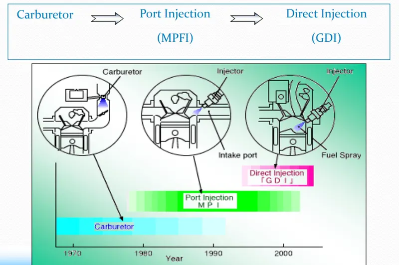
#ADVANTAGES OF FUEL INJECTION OVER CARBURETOR
1.Fuel injection has no choke, but sprays atomized fuel directly into the
engine.
2.Electronic fuel injection also integrates more easily with computerized
engine control systems.
3.Multi port fuel injection delivers a more evenly distributed mixture of
air and fuel to each of the engine's cylinders.
4.Sequential fuel injection improves power and reduces emissions.
#In indirect fuel is injected into the air stream before entering the combustion chamber. And in direct injection system fuel is injected directly inside the combustion chamber.
#Single Point Injection system:
The earliest & simplest type of fuel injection, single point simply replaces the carburetor with one or two
fuel injector nozzles in the throttle body, which is the throat of the engine’s air intake manifold. Single point injection system meters fuel better than a carburetor and is less expensive and easier to service.
#Throttle Injection:
The indirect injection can be classified as single point injection and multi point fuel injection.The single point injection also called Throttle injection in which fuel is injected at one place in throttle body, and the mixture supply to different cylinders.
#Port injection:
In case of Port injection also called multi point fuel injection, air sucks through throttle body, and
fuel is injected near inlet valve of every cylinder .
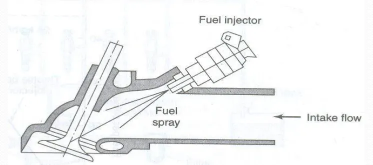
#Multi Point Fuel Injection System(MPFI)
a.)MPFI system is widely used in petrol engine in place of carburetor.
b.)Purpose of MPFI is supply proper A/F ratio to each cylinder of engine.Fuel tank > Pump > High pressure petrol > Distributor> Fuel injector > Cylinder
c.)Now a days MPFI system control by Electric Control Module (ECM).Ecm receives signal from different sensors.
d.)ECM receives signal and send to the solanoid operated fuel injector to meter and inject right amount of fuel at right time.
-----------------------------------------------*******************-------------------------------------------
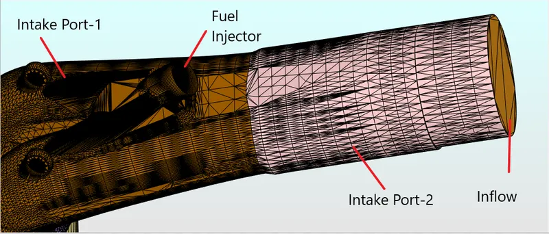
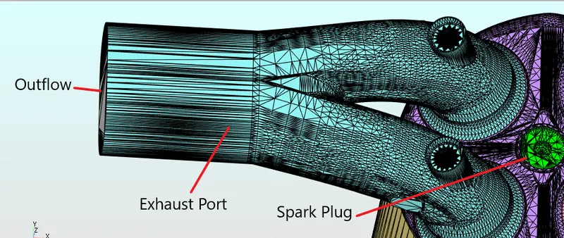
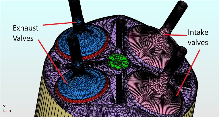
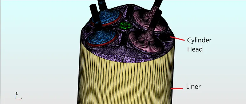
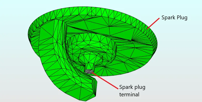
#Geometry:
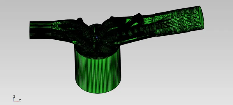
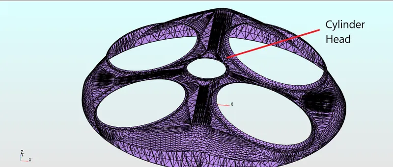
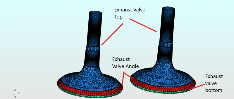
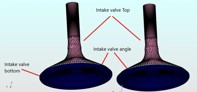
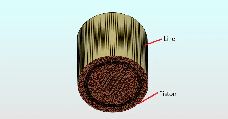
#Flagged geometry:
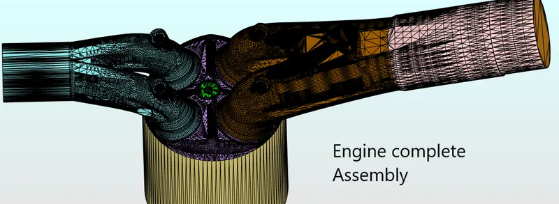
---------------------------------------------******************--------------------------------------
#Case setup:
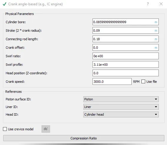
1.Application type-Crank Angle based(i.e IC engine)
Engine Geometric Parameters
- Bore =0.086 m
- Stroke = 0.09 m
- Connecting rod length = 0.18 m
- RPM = 3000
2.Materials:
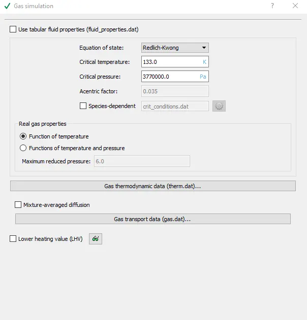
Enable-Gas and Parcel simulation
a.)Gas simulation:
b.)Parcel simulation:
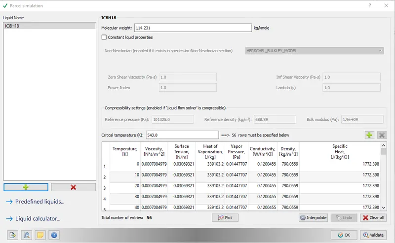
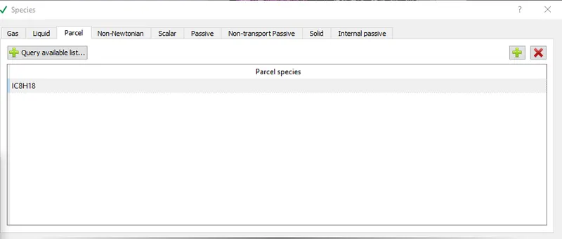
#Select Parcel Simulation
Inside Parcel simulation,choose IC8H18(iso-octane),because physical properties of iso-octane resemble properties of Gasoline used in our vehicle.Physical properties like viscocity,surface tension,heat of conductivity,density as a funtion of temperature.This should be kept in mind while selecting species for parcel,otherwise spray prediction,fuel vapourisation and combustion prediction that would be given by software ,would be wrong .
# Global transport properties-Default
#Reaction mechanism:
Import prepared reaction mechanism file
#Species:
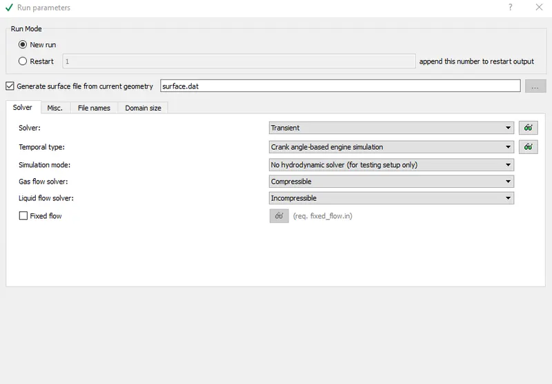
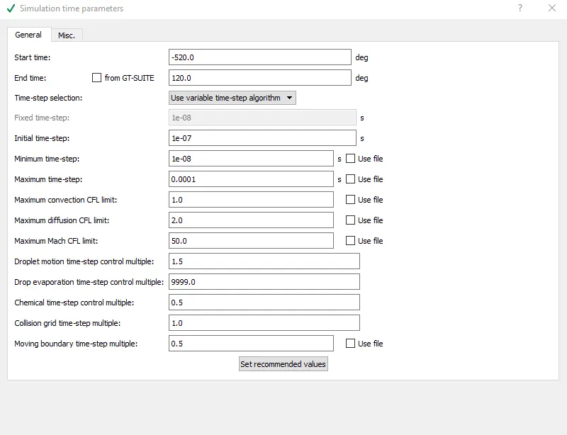
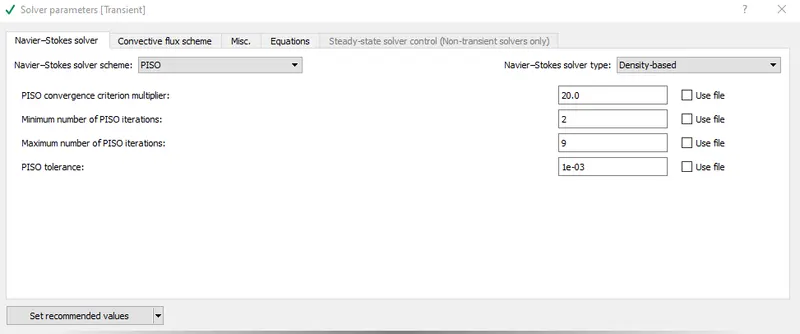
3.Simulation Parameters:
4.Boundary Conditions:
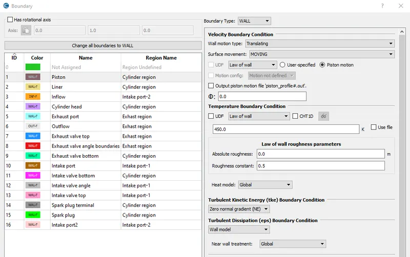
1.Piston temperature - 450K
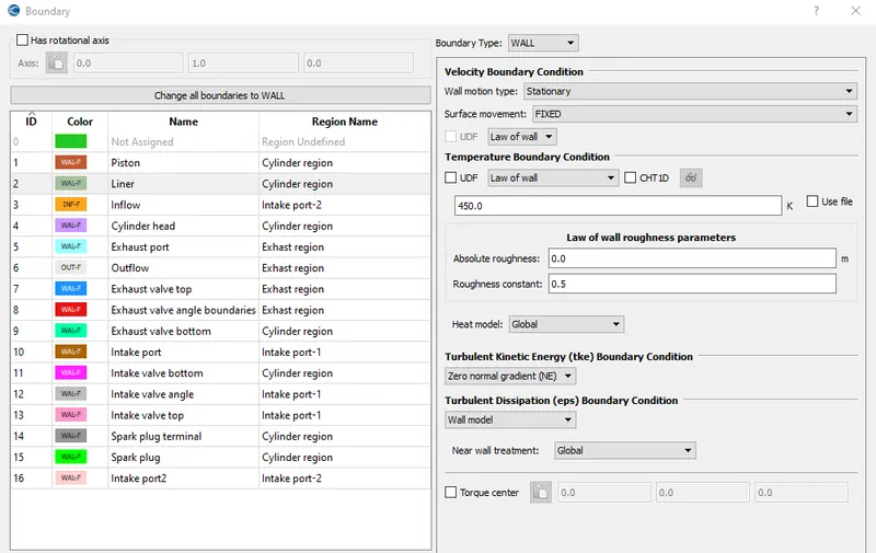
2.Liner temperature - 450K
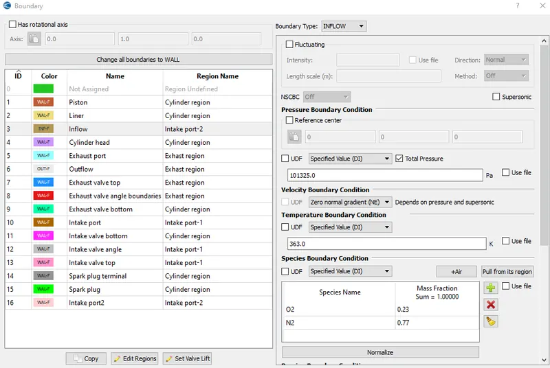
3.Inflow temperature - 363K:
Inflow pressure - 1 bar total pressure
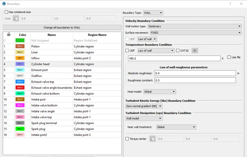
4.Cylinder Head temperature - 450K:
5.Exhaust ports temperature - 500K:
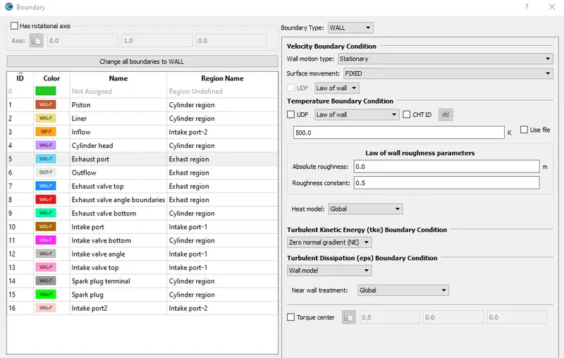
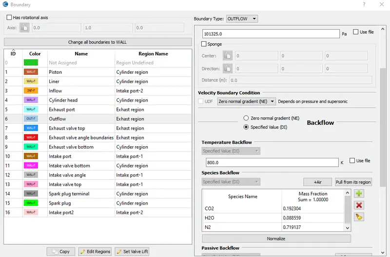
6. Exhaust outflow - 1 bar
Exhaust outlflow temperature - 800k
Since exhaust gases will contain product formed after combustion of fuel inside cylinder.
Therefore it contain species CO2,H2O & N2.
By following combustion reaction:
C8H18 + 12.5(O2+3.76N2)--->>> 8CO2 + 9H2O + (3.76*12.5)N2
Mole fractions of CO2,H2O and N2 found out:
Mole fraction of CO2=0.192304
Mole fraction of H2O=0.088559
Mole fraction of N2=0.719137
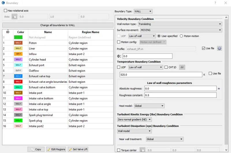
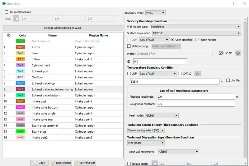
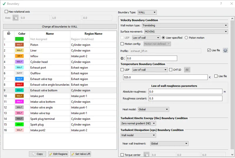
####As Exhaust and Intake valves will move up and down during simulation.Therefore for exhaust and intake valves all parts ,lift profile file is used.
7.Exhaust valve top temperature - 525K
8.Exhaust valve angle temperature - 525K
9.Exhaust valve bottom temeprature - 525K
10.Intake port - 1 temperature 425K:
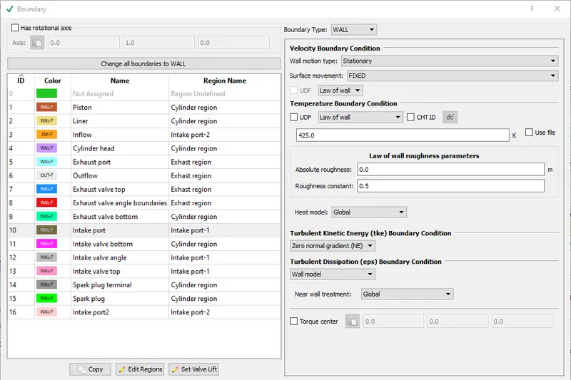
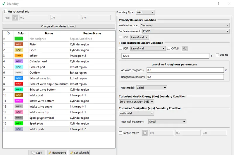
11.Intake port - 2 temperature 425K:
12.Intake valve top temperature - 480K
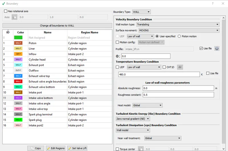
13.Intake valve angle temperature - 480K
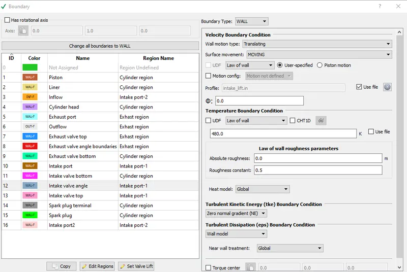
14.Intake valve bottom temeprature - 480K
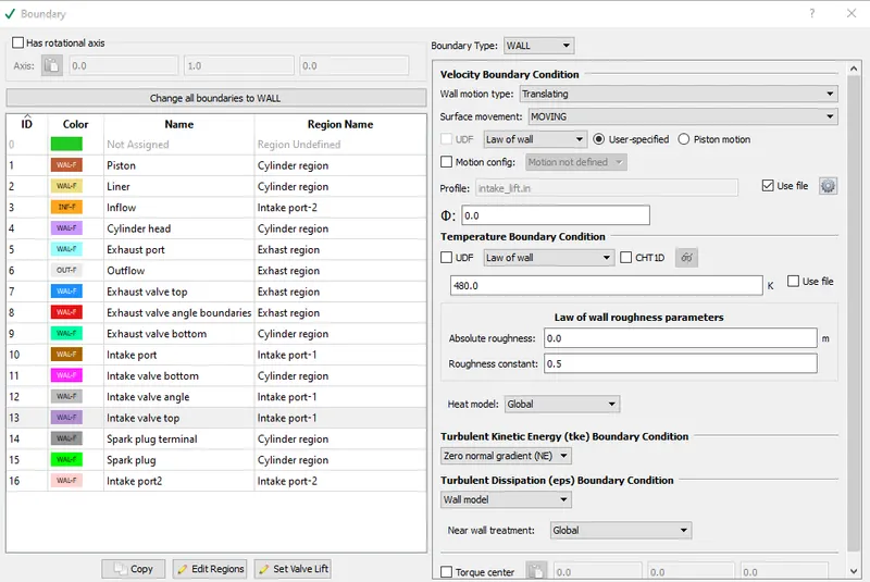
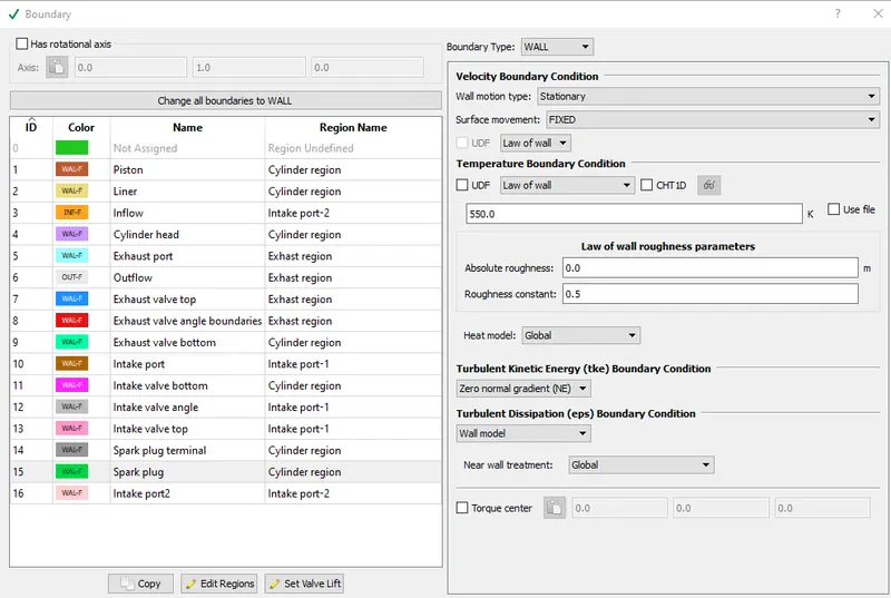
15.Spark Plug temperature - 550K:
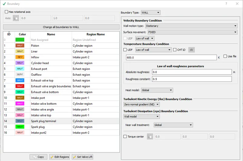
16.Spark Plug electrode temperature - 600K
Due to spark generation at this terminal ,Temperature here is more as compared to some other sections.
5.Initial conditions and events:
1.Regions and initialization:
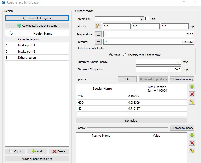
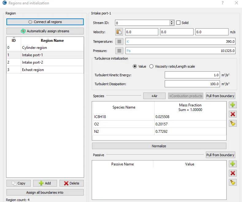
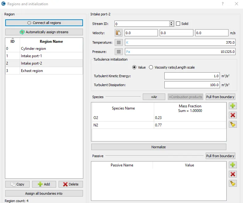
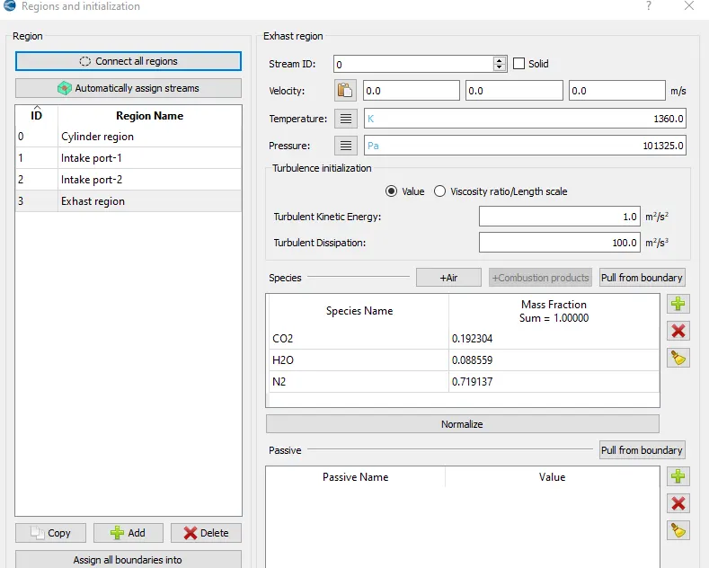
##Cylinder and exhaust region initialised with same combustion products ,as product from combustion will go to exhaust side.
Intake port near cylinder has fuel injector so it is initialised with some content of fuel along with air,Intake port away from cylinder head only has air while initialising.
2.Events:
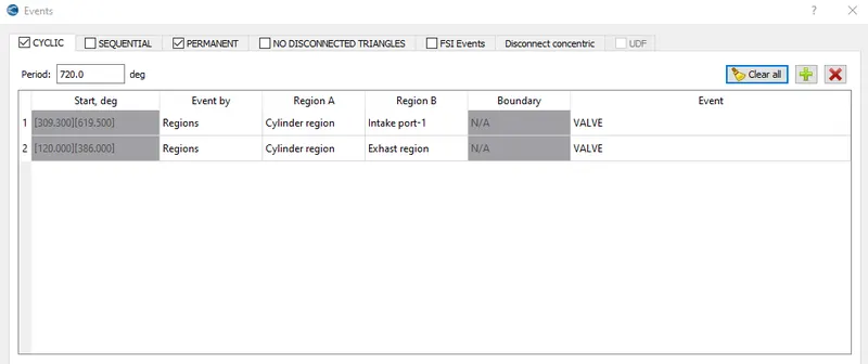
##Events created between Cylinder and Intake region -1 for controlling timing of injection of fuel and air mixture into the cylinder on the basis of crank shaft position.
And one more events created between cylinder and exhaust region to control removal of exhaust gases from cylinder after combustion has been completed on the basis of crank shaft position.
Prepared file is used for both exhaust and inlet valves lift.
6.Physical Models:
#Spray Modeling:
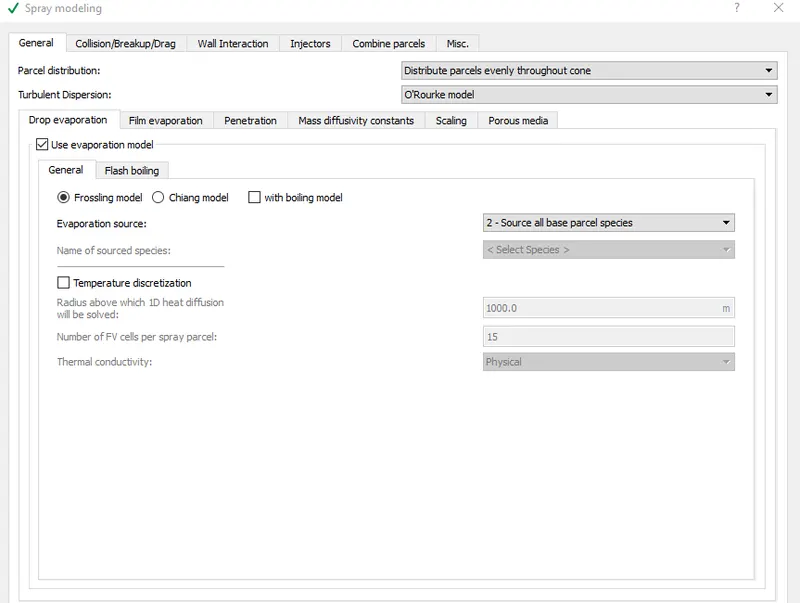
In general option,
Parcel distribution-select-Distribute parcels evenly throughout cone--this better describe spray for gasoline fuel
Turbulent dispersion:select-O'Rourke model--this better describe spray for gasoline fuel
#Evaporation model-Tell rate at which parcel going to evaporate.
#Radius above which ODE would be solved is kept large ,so that ODE won't be solved for droplets and simulation would run faster.
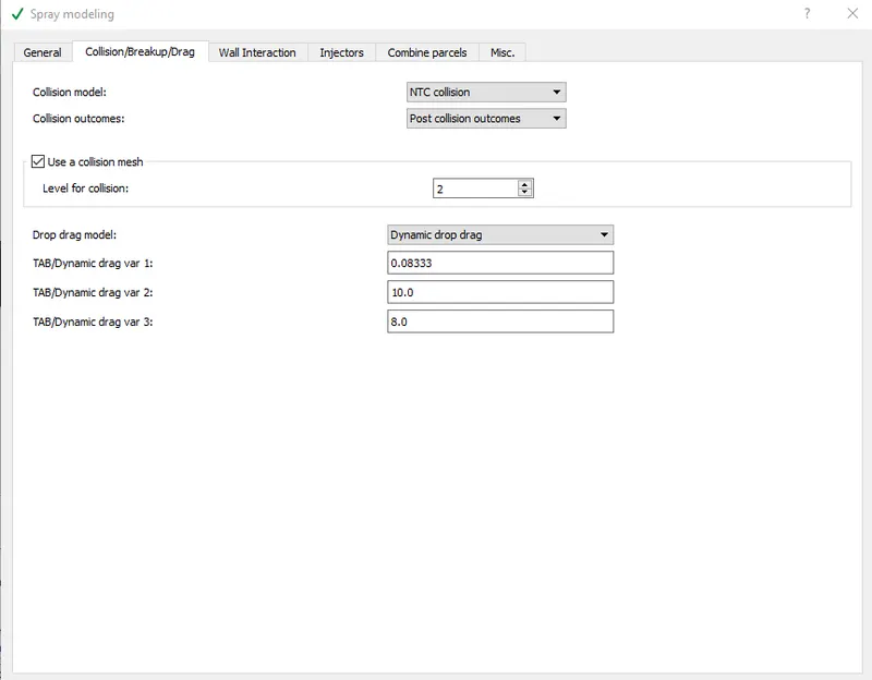
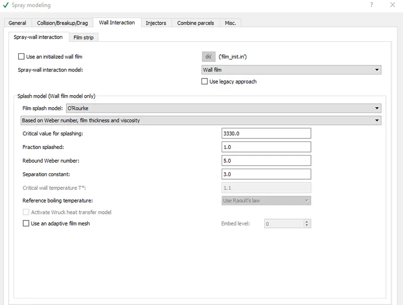
#In Wall interaction,
Select wall film-we want wall film to be formed.
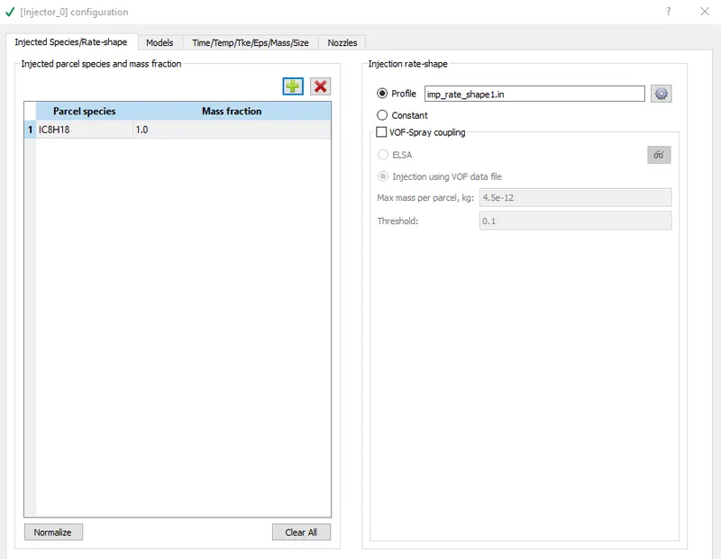
#In Injectors:
Parcel species-IC8H18
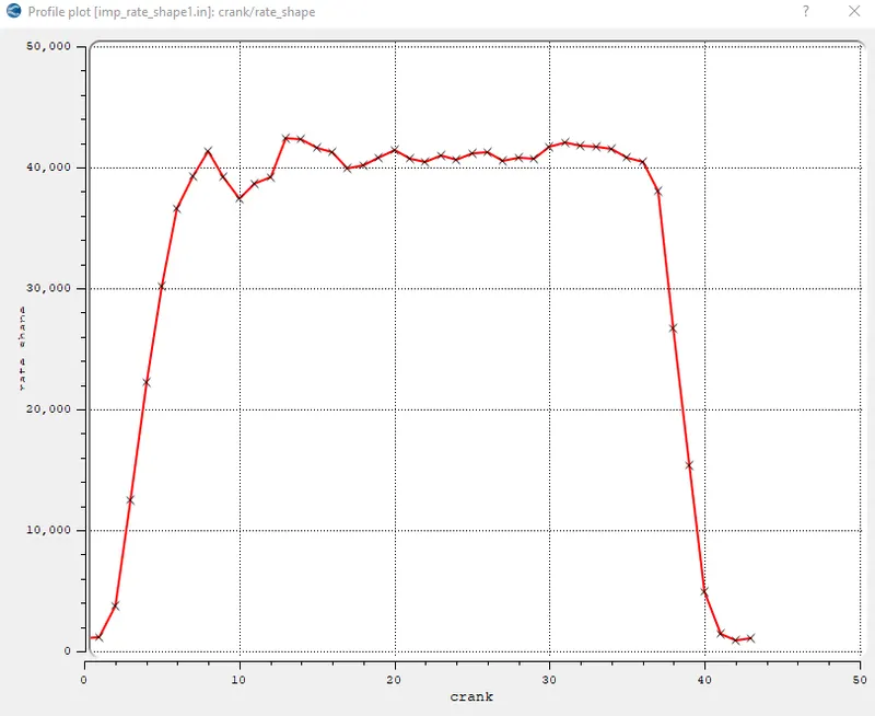
*Import injection rate shape prepared file.
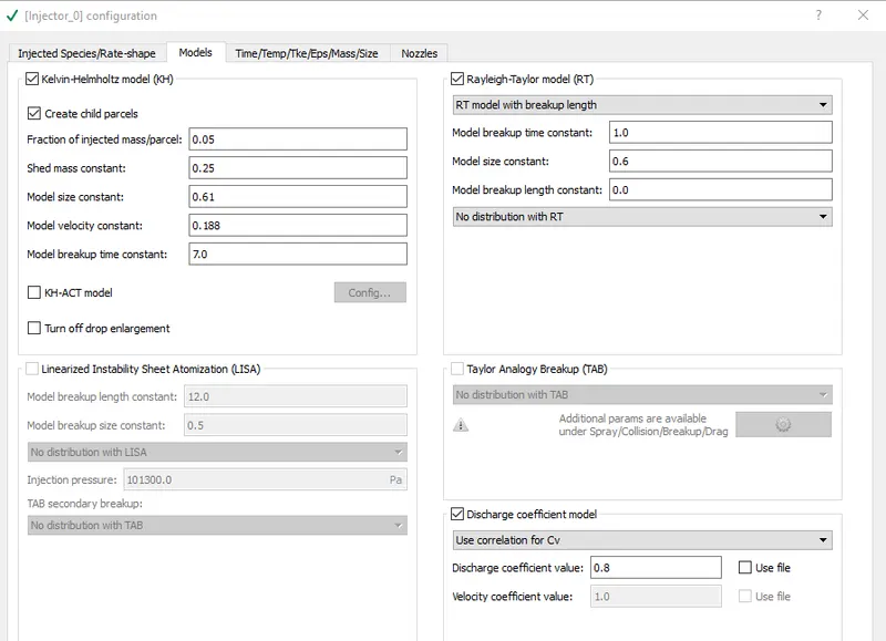
#Select KH+RT models:
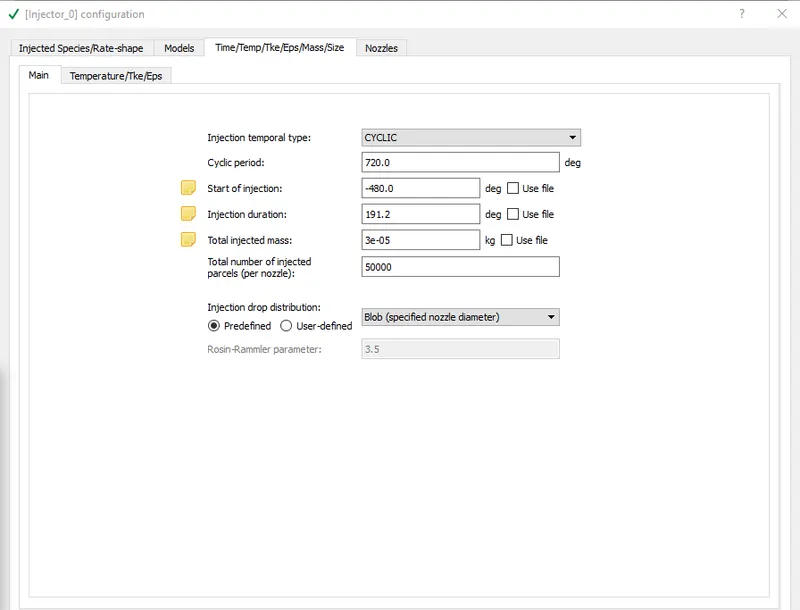
#Injection mass:
Flow rate for fuel injected kept =7.5e-4 kg/sec
So by calculating for 3000 rpm of engine and 720 degrees.
Fuel mass injected per cycle= 3e-5 kg/cycle
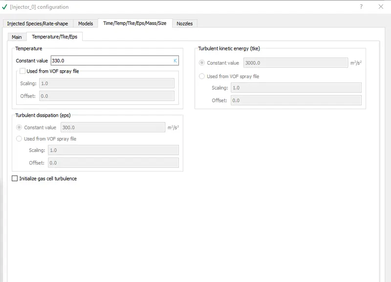
#Temperature of fuel injected kept=330 Kelvin
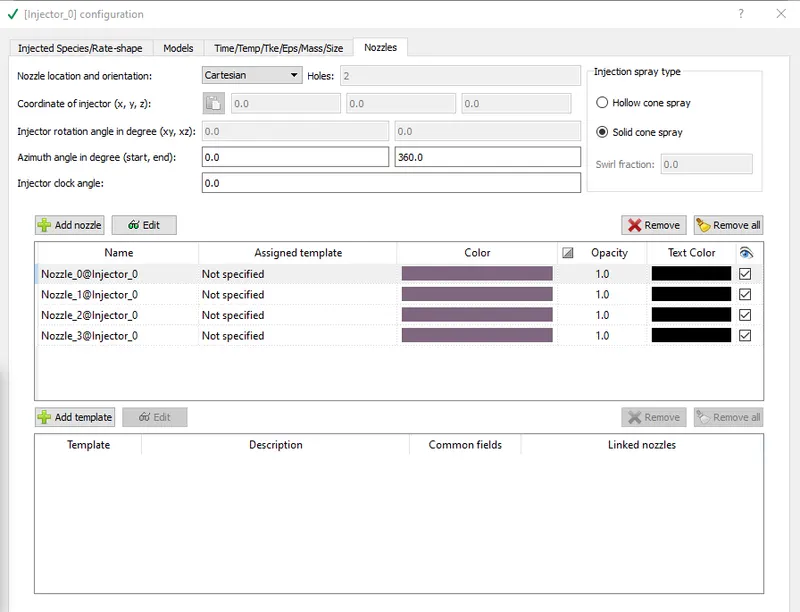
#Define 4 nozzles one by one:
Nozzle positions
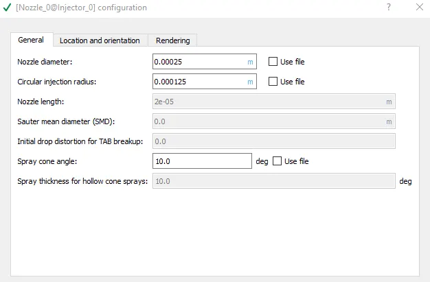
Nozzle diameter = 250 micro-meter
Circular injection radius = Nozzle radius
Spray cone angle = 10
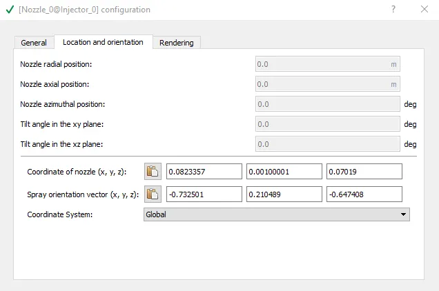
- Nozzle 0
- center 0.0823357 0.00100001 0.07019
- Align Vector -0.732501 0.210489 -0.647408
- Nozzle 1
- center 0.0823357 -0.00099999 0.07019
- Align Vector -0.732501 -0.210489 -0.647408
- Nozzle 2
- center 0.0823357 -0.0004 0.07019
- Align Vector -0.5 -0.2 -0.647408
- Nozzle 3
- center 0.0823357 0.0003 0.07019
- Align Vector -0.5 0.2 -0.647408
#For particular nozzle ,set diameter,location and orientation provided .
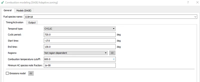
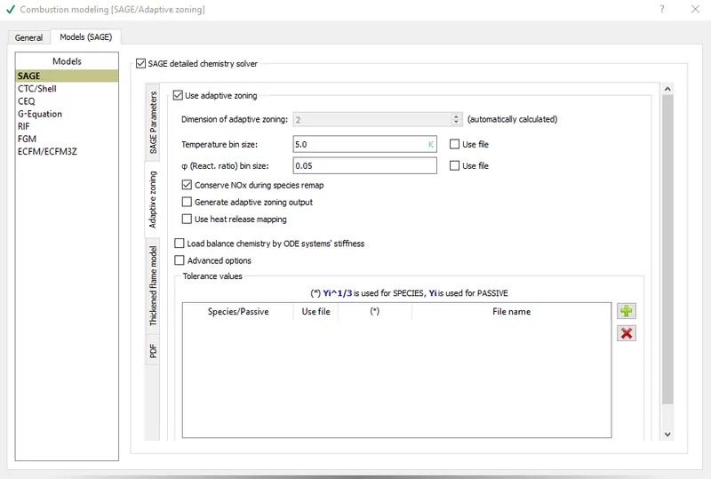
#Combustion Modeling:
Set the start time for combustion just some degree before spark ignite,so that solver would be ready till the time of spark ignition.
#Turbulence Modeling-RNG k-epsilon model
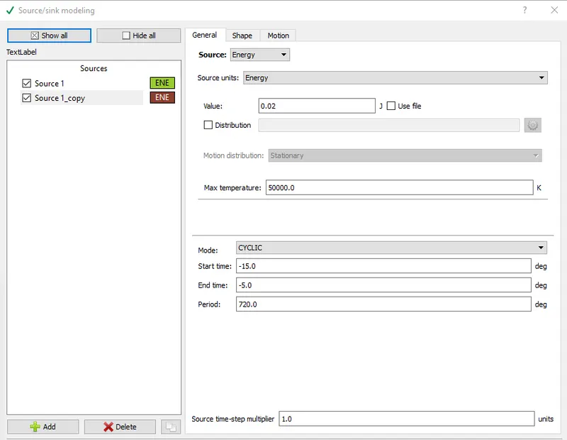
#Source/Sink modeling:
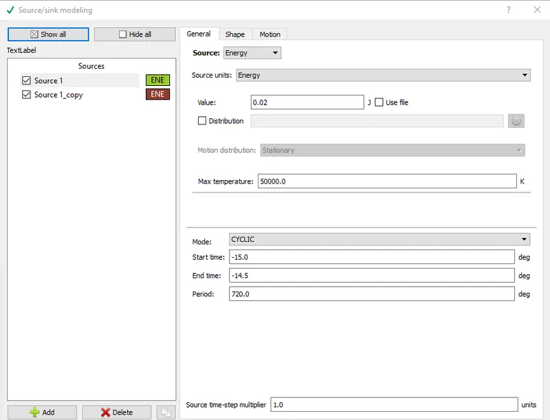
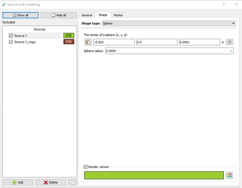
As it is a PFI engine using iso-octane(whose properties resemble Gasoline),it need a spark to ignite fuel-air compresed mixture.
So an energy source is provided.
For -15 to -14.5 crank angle,total 40 MJoule of energy given to initiate combustion then,from -15 to -5 degrees only 20 MJoule energy given to sustain combustion already initiated.
7.Grid control:
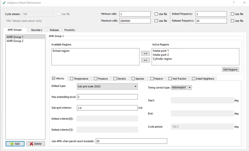
Enable -1.)Adaptive mesh refinement
2.)Fixed embedding
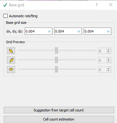
1.)Adaptive mesh refinement:
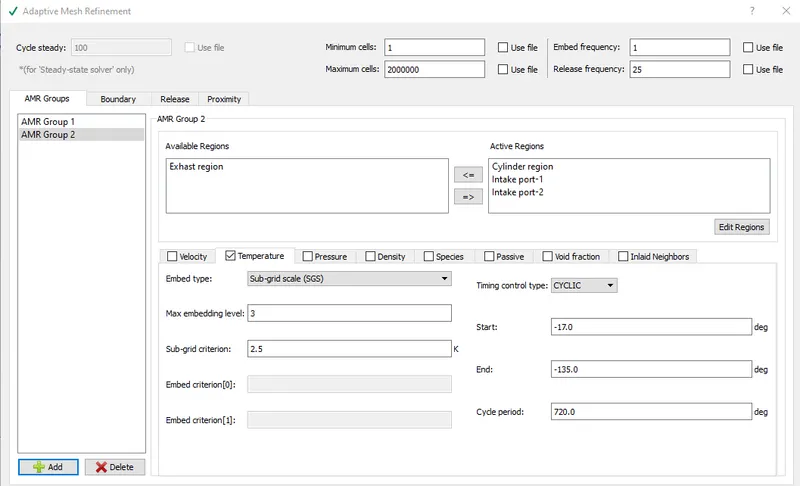
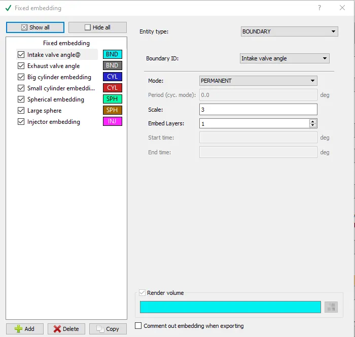
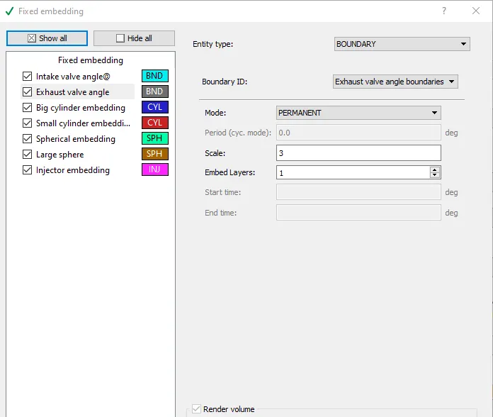
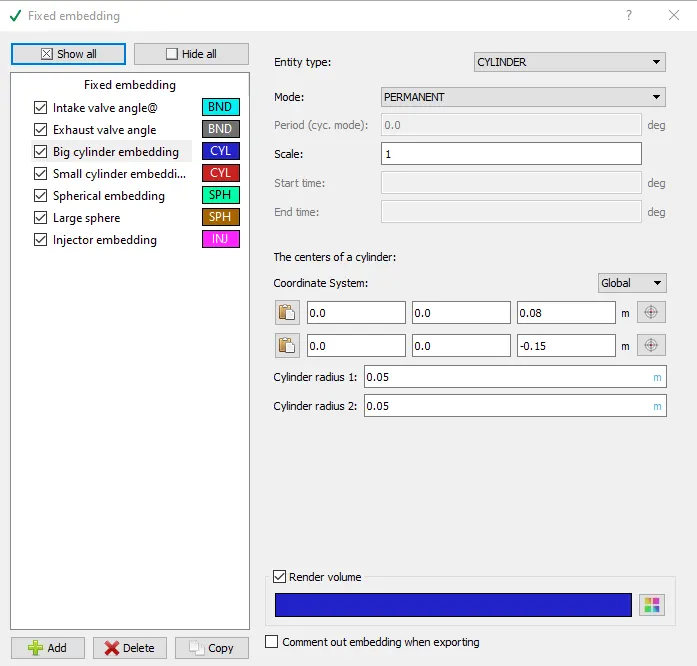
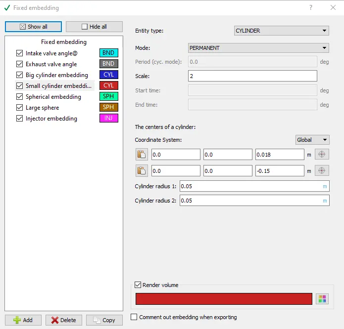
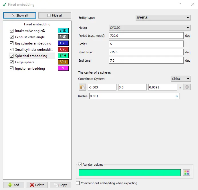
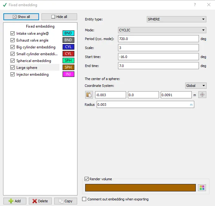
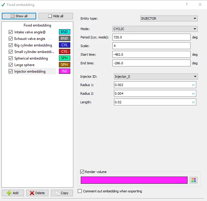
2.)Fixed embedding:
--------------------------------------------*******************--------------------------------------
# Results:
#Inside combustion chamber:
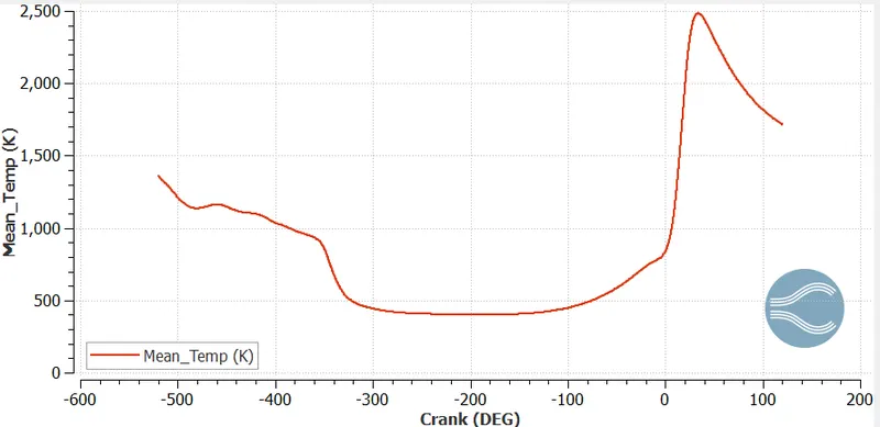
1.Mean Temperature plot:
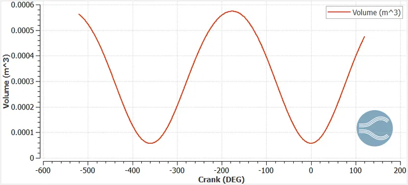
2.Volume varition inside cylinder due to piston movement:
.
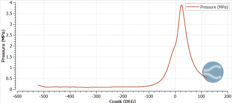
3.Pressure plot:
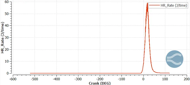
4.Heat release rate plot:
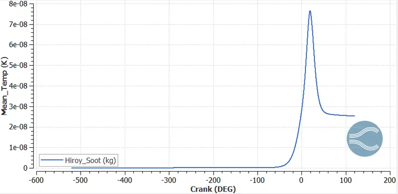
5.Soot plot:
------------------------------------------------*********************--------------------------------------
#Clips of animation:
-----------------------------------------------***************-----------------------------------------
#1. What is the compression ratio of this engine?
Ans.The compression ratio (CR) is defined as the ratio of the volume of the cylinder and its head space (including the pre-combustion chamber, if present) when the piston is at the bottom of its stroke to the volume of the head space when the piston is at the top of its travel (‘top dead centre’, tdc). Typically, petrol engines have a CR of 8–10, while diesel engines have a CR of 15–20. The CR of petrol engines is limited by the requirement that the fuel burns uniformly in the cylinder and does not ignite thermally prior to the spark (so-called ‘engine knocking’). In a spark-ignition engine, the CR at which pre-ignition takes place is determined by the octane number of the petrol; High-octane fuel permits a high CR.
Compression ratio= (Swept Volume + Clearance Volume)/Clearance Volume
Clearance volume for the gven engine:`V_c=5.7029438e-005``m^3`
Swept Volume for the gven engine:`V_s=5.7421950e-004` `m^3`
Compression ratio=Cr=`(V_s+V_c)/V_c`
`Cr=(5.7421950e-004+5.7029438e-005)/(5.7029438e-005)`
`Cr=11.068826`
------------------------------------**************************************--------------------------
#2.Why do we need a wall heat transfer model? Why can't we predict the wall temperature from the CFD simulation.
Ans.We have used Turbulence model,Spray,Combustion model for simulating injection of fuel,mixing of fuel ,combustion of fuel for this engine to understand for given engine ,by injecting certain fuel what would be the peak pressure,Temperature,Power,Torque,IHR etc.
These calculations are for combustion chamber only but what would be the effect of combustion temperature on piston,liner,cylinder,coolant need to be done using CHT analysis.
With time how heat transferring from gas to wall,wall to wall and wall to liquid require CHT analysis.
--------------------------------------------------************------------------------------------------
#3. Calculate the combustion efficiency of this engine
Ans.Combustion efficiency of an engine=Integrated Heat Release(IHR)/Total heat content of fuel
`eta_(combustion)=(IHR)/(m*CV_(fuel))`
#From the converge plot shown below,maximum value of IHR=1.2411646e+03 (Joule)=1241.165(J)
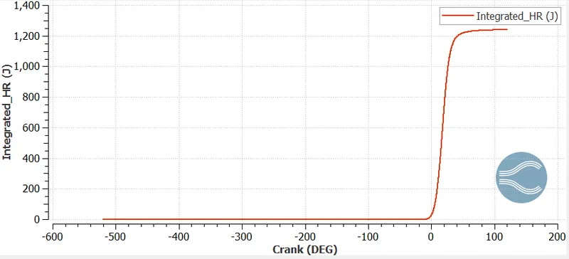
Calorific value of Iso-octane at standard condition = 47777 J/g.=47777*1e+03 (J/Kg)
Calorific value of Iso-octane at standard condition =47.78*1e+06 (J/Kg)
Total Mass of fuel injected in 720 degrees of crank angle=3e-05 (Kg)
Total heat content of fuel=47.78*1e+06 *3e-05 (Joule)
Total heat content of fuel=1433.4 (J)
`eta_(combustion)=1241.165/1433.4=0.865888`
`eta_(combustion)=86.5888%`
--------------------------------------------------***************--------------------------------------
4. Use the engine performance calculator, to determine the power and torque for this engine.
Ans.Using Converge Engine performance calculator tool,
Gross Work done by engine for 240.199 Crank angle=W =468.646 N-m
#Power Calculation:
Since ,Engine rpm=3000
Rotation per second=rps=50
And one rotation of crank = 360 degrees
Therefore,
Total degrees turned by crank in 1 sec=50*360=18000
Time required to turn 18000 degrees =1 sec
Then ,time required to turn 240.199 degrees= 0.013344 sec
Power= Work done/Time
`P=468.646 /0.013344 =35120.35 W`
#Torque calculation:
`Power=P=(2*pi*N*T)/(60)`
`T=(P*60)/(2*pi*N)`
`T=(35120.35)*60/(2*pi*3000)=111.8489 N-m`
-------------------------------------------***********************----------------------------------------
# 5. What is the significance of ca10, ca50 and ca90.
Ans.Term CA represent Crank Angle.CA10,CA50and CA90 represent Crank angle at which 10%,50% and 90% fuel has burnt or combustion has taken place respectively.
Significance of these terms CA10,CA50and CA90 are that during experimental analysis of an engine these points are used to study the combustion behaviour of an engine.While doing any modification on engine,changing loads ,operating conditions etc what would be the change in these points,would it be delayed or prompted.
-----------------------------------------------******************------------------------------------