Week 10: Project 1 - FULL HYDRO case set up (PFI)
Objective:-
1. Perform the no hydro simulation in a Port Fuel Injection engine examine the valve and the piston movement.
2. Perform the full hydro simulation of the engine and study the spray parcel distribution and flame propgation of the engine.
3.Find the compression ratio , power, torque, combustion efficiency of the PFI engine.
4. What is the significance of ca10, ca50 and ca90?
Introduction
Four basic type of fuel injection system is used in the internal combustion engine namely throttle body injection ,port fuel injection, sequential fuel injection and direct injection.
Direct injection has the injectors mounted in the cylinder head and the injector spray fuel directly in to the engine cylinder then mixes with the air, only air passes through the intake manifold runner.
Port injection spray the fuel in to the intake ports where it mixes with the incoming air, port injection systems are much cheaper to manufacturer. The injector are not exposed to the high heat and pressure of the combustion chamber. Port injection system typically operate in the 30 to 60 psi range which is drastically lower than direct injection system. Port injection systems spray the fuel on the back side of the intake valve and the fuel has to wait till the valve open. Fuel sprayed on the back side on the intake valves also cleans the valves.
Port fuel injection system replaced carburator in cars because of their efficiency and lower maintainance requirement.
Boundary flagging and surface preparation
The given geometry is imported by drag and drop method
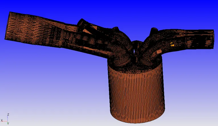
Given dimensions
- Bore =0.086 m
- Stroke = 0.09 m
- Connecting rod length = 0.18 m
- RPM = 3000
Step involved in surface preperation
1.Diagnosis is carried out and all the surface fault are detected
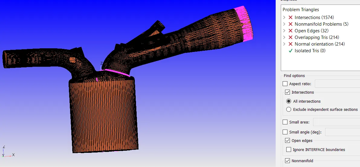
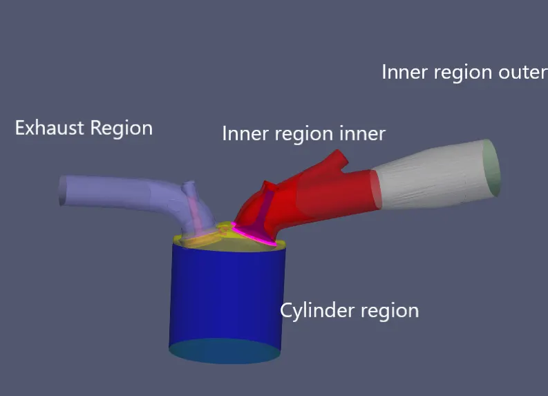
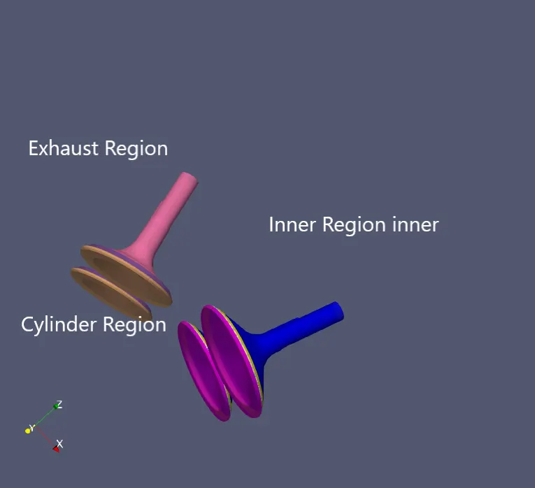
Boundary flagging is carried out
Image of boundary flagging
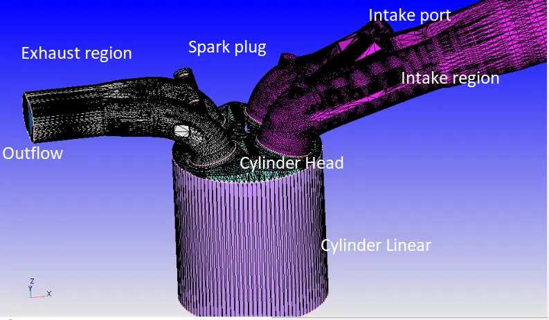
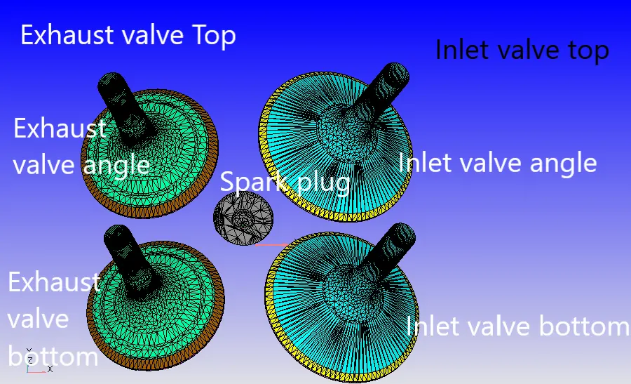
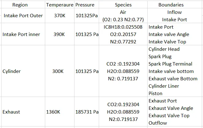
Flagged part classified in to four part namely
1. Intake region outer
2. Intake region inner
3.Cylinder region
4.Exhaust region
Case Seup
Full hydro simulation
Crank based IC engine simulation is selected
Run Parameter
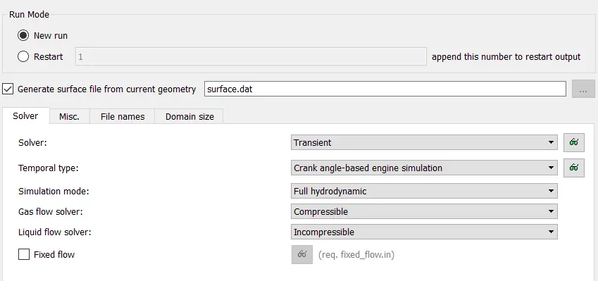
Air is chHosen as the material ,parcel modeling , reaction mechanism . therm.dat is imported for the thermodynamic data. IC8H18 is selected for parcel simulation.
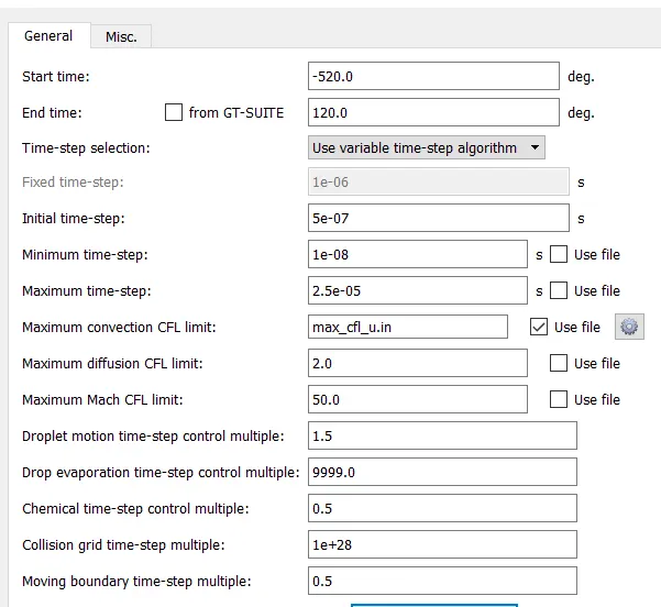
Simulation Time Parameter
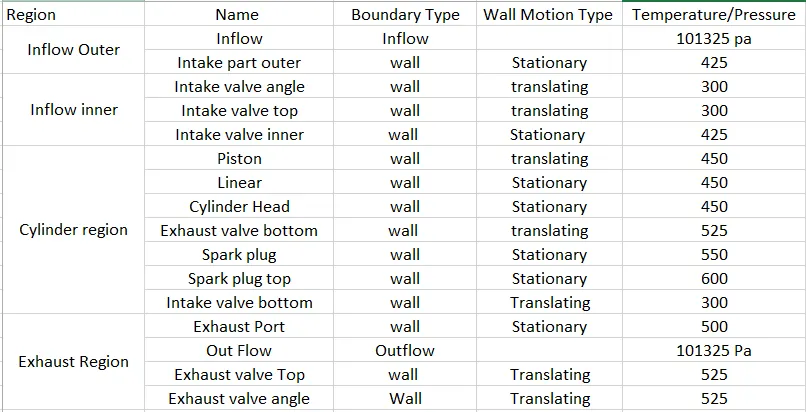
Boundary Condition
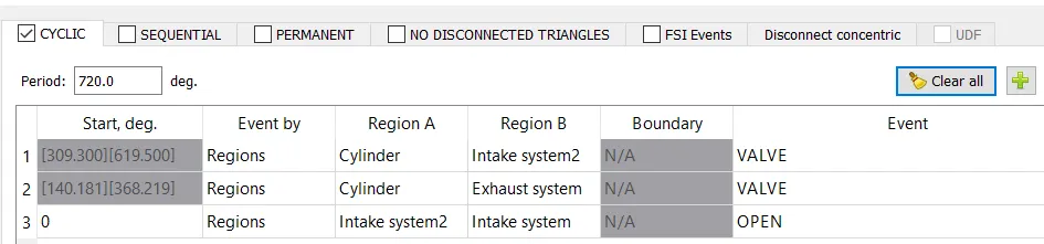
Events
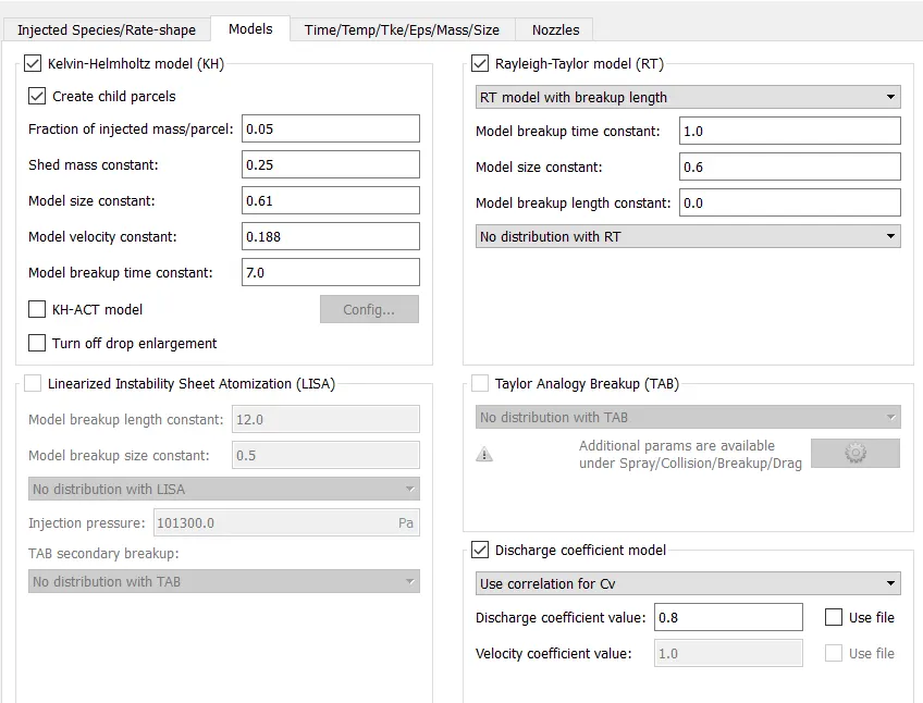
Spray Modeling
Spray is introduced into the system in the form of lagrangian parcels each parcel consist of droplet. Additional source are introduced to define the intraction between eulerian phase and lagrangian phase.
Different type of interaction seen between these two phases such as primary secondary collision and evaporation etc.
The spray can be represented in the form of two types cones , first where the particles are clustered at the cone centered second where the particles are distributed along the spray cone.
O'Rourke model is used to turbulent dissipation and frossling model is used for evaporation.
Collision Model:NTC Collision
Post collision outcomes: Collision Mesh
Check mark on use a collision mesh
Drop drag model -Dynamic drop drag
Spray wall interaction: Wall film
Film splash model: O' Rourke
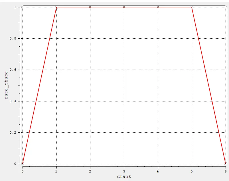
The rate shape of injection is in the form of a trapezoid as shown below
Parcel Species: IC8H18(Iso-Octane)
Start of injection--480 degree
Injection Duretion-191.2 degree
Injection mass 3e-5 kg
Temperature-330K
Nozzle diameter = 250 micro-meter
Circular injection radius = Nozzle radius
Spray cone angle = 10
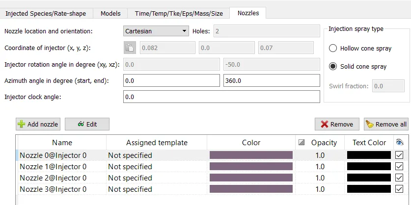
- Nozzle 0
- center 0.0823357 0.00100001 0.07019
- Align Vector -0.732501 0.210489 -0.647408
- Nozzle 1
- center 0.0823357 -0.00099999 0.07019
- Align Vector -0.732501 -0.210489 -0.647408
- Nozzle 2
- center 0.0823357 -0.0004 0.07019
- Align Vector -0.5 -0.2 -0.647408
- Nozzle 3
- center 0.0823357 0.0003 0.07019
- Align Vector -0.5 0.2 -0.647408
Insert the four nozzle in the above location by using edit option
SAGE Chemistry Model is used
Turbulence Modeling -RNG k-epsilon
Source/ Sink Modeling
During the ignition of the fuel generation of the spark, higher energy is required during break down phases as compared as the propgation of the spark there fore higher energy is provided during phase modeling. Detail of the sources are given below.

Adaptive Mesh Refuinment
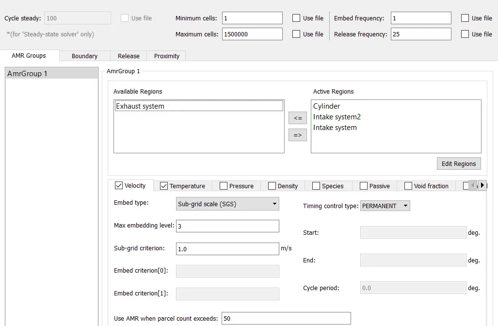
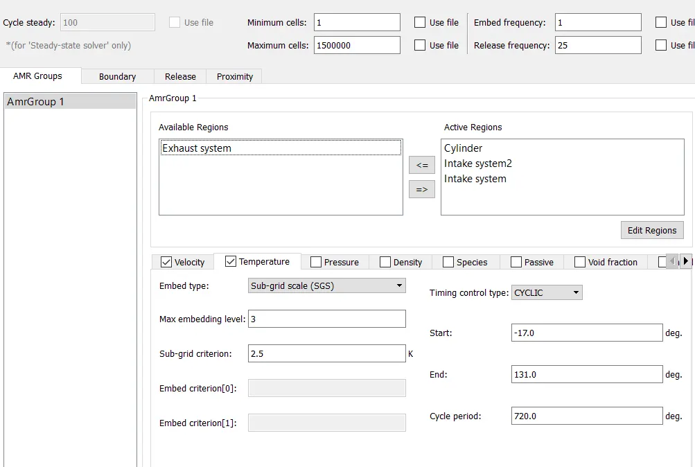
Amr autometically increases the grid resolution based on curvature in the field variables it can be parmanent at specific time and Amr is activated by region basis.
Fixed Embadding
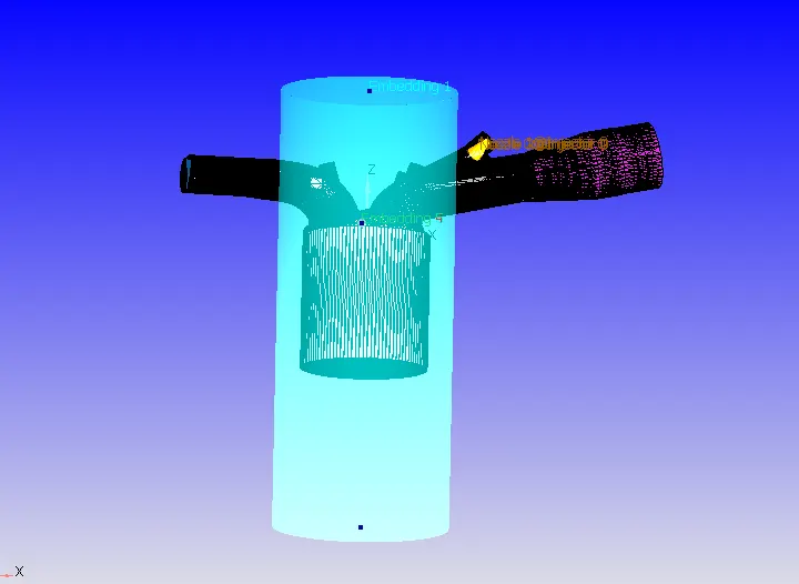
Fixed embadding applied to the various region
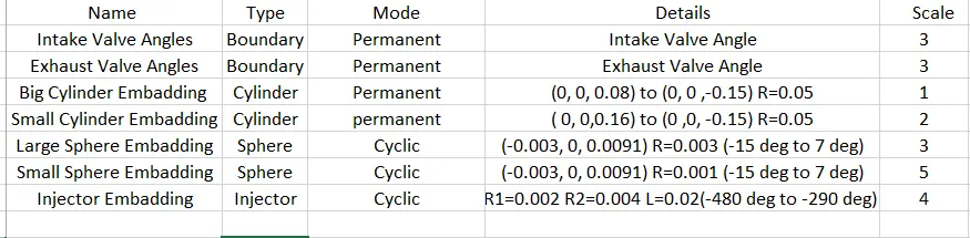
Fixed embadding is used to create highly refined region for very few crank angles so the temperature AMR seed the large gradient changes. The cylindrical embadding is provided to get a finer mesh in the combustion zone of the cylinder region.
Spherical embadding is provided for the source term modelled in order to get a better refinement at the region of generation of the spark and its propgation.
The injector embedding is used for the injector as spray parcels , this is required for better application of velocity AMR at the intake port .
Snap shot of fixed embadding
Combustion equation of cylinder is
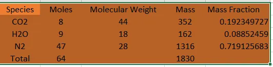
`C_8H_(18)+12.5(O_2+3.76N_2)rarr8CO_2+9H_2O+(3.76xx12.5)N_2`
The above equation is stiochimetrically balanced and hence the mole fraction is converted in to mass fraction.
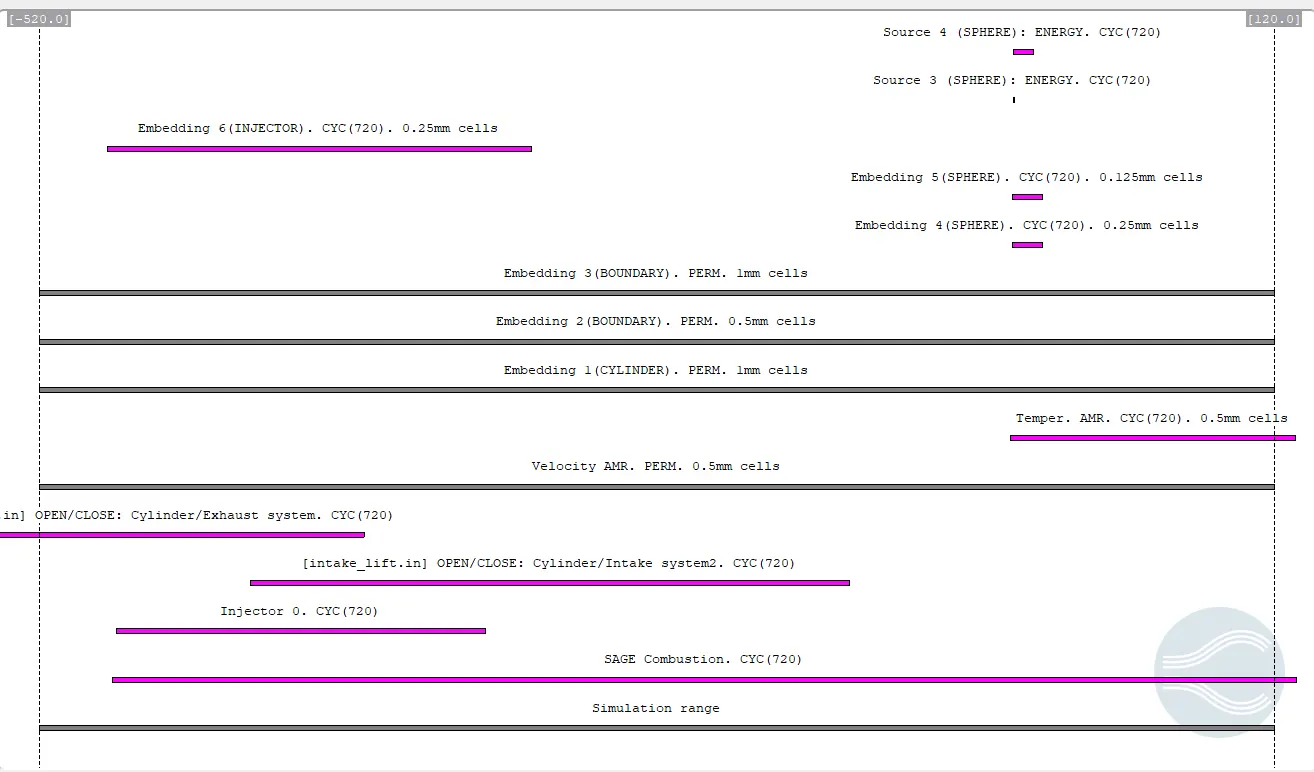
Snap Shot Of Timing Diagram
Initial condition for the various region
Result
The fuel is modeled in the form of sprayand is injected in to the engine towards the startof the intake stroke just before opening of the intake valves. the movement of the spray parcel can be observed in the video clip.
https://www.youtube.com/watch?v=ADzgn9xBeTI
Various engine Performance parameter can be calculated from performance calculator in converge
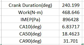
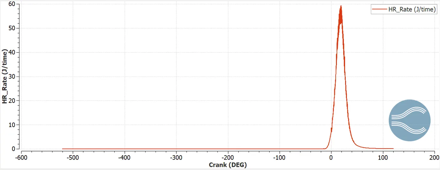
CA10 represent that crank angle at which 10 percent of the fuel has been combusted, similary CA50 and CA90 signify the crank angles at which 50% and 90% of the combustion has taken place.
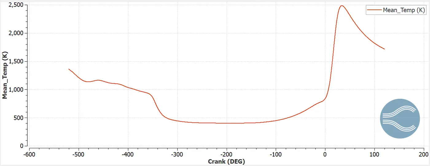
Line plot of mean temperature along the cylinder region
Line plot of variation of pressure along the cylinder region
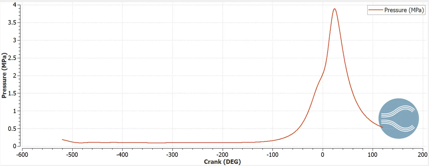
From the above mean temperature and pressure plot we can say that maximum pressure and temperature occurs between 0 to 35 degrees thereafter temperature and pressure decreases for both the quantity.All 90% of the combustion takes place before 35 degree of crank angle.
Stream line
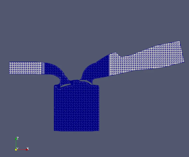
Section view of cylinder
The mesh is generated along with the embadding with the various zone
Power calculation
RPM=3000
W=468.646 N-m
RPS=3000/60=50
50 cycles completed in 1 sec
50*360 degree completed in 1 sec
1 degree completed in 1/(50*360) sec
240.199 degree completed in `1/(50xx360)xx240.199` sec`
Time for 240.199 degree (t)= `1/(50xx360)xx240.199` sec`
`Powder=(W o r k) /(Time)`
`P=W/t`
`P=(468.646xx50xx360)/(240.199)`
P=35119.33 W
Torque calculation
`P=(2pi NT)/60`
`T=(pxx60)/(2piN)`
`T=(35119.33xx60)/(2pixx3000)`
`T=111.788 Nm`
Compression Ratio
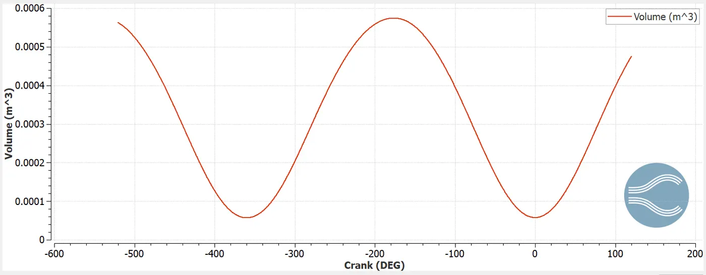
Compression ratio, in an internal-combustion engine, degree to which the fuel mixture is compressed before ignition. It is defined as the maximum volume of the combustion (with the piston farthest out, or bottom dead centre) divided by the volume with the piston in the full-compression position (with the piston nearest the head of the cylinder, or top dead centre). A compression ratio of six means that the mixture is compressed to one-sixth its original volume by the action of the piston in the cylinder.
Combustion Efficiency(`eta_c`) calculation
Combustion efficiency, defined as the ratio of heat released by the fuel to the heat input by the fuel.
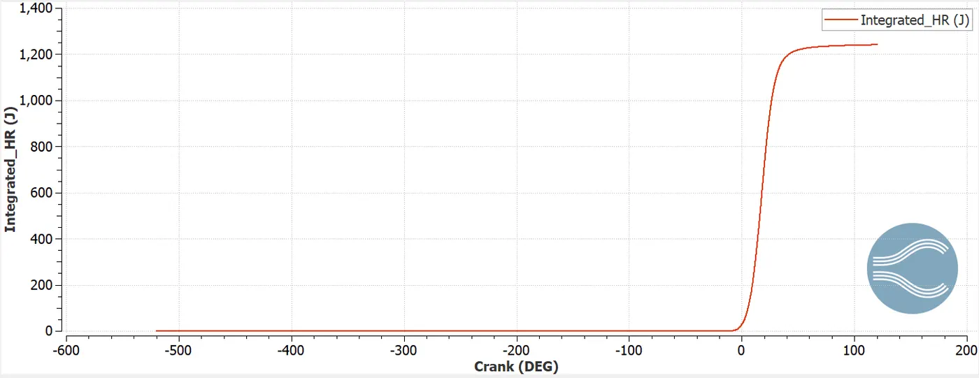
`eta_c=` Integrated heat released(`IHR`)/Total heat content in the fuel(`mxxCV_(fuel)`)
IHR= 1241.13 J (From plot)
m=`3xx10^-5`
CV=44 MJ/kg
`eta_c=(1241.13)/(3xx10^-5xx44xx10^6)`
= 0.93
Why do we need a wall heat transfer model? Why can't we predict the wall temperature from the CFD simulation?
In order to perform good prediction of engine heat transfer and wall heat transfer model are required for accomplish heat transfer from hot gases to engine parts, heat transfer inside each engine part and also heat transfer to coolant and lubricant oil.
Compression Ratio of the engine (CR)
`CR=V_(max)/V_(min)`
`=0.000573958/(5.75392*10^-5)`
=9.97
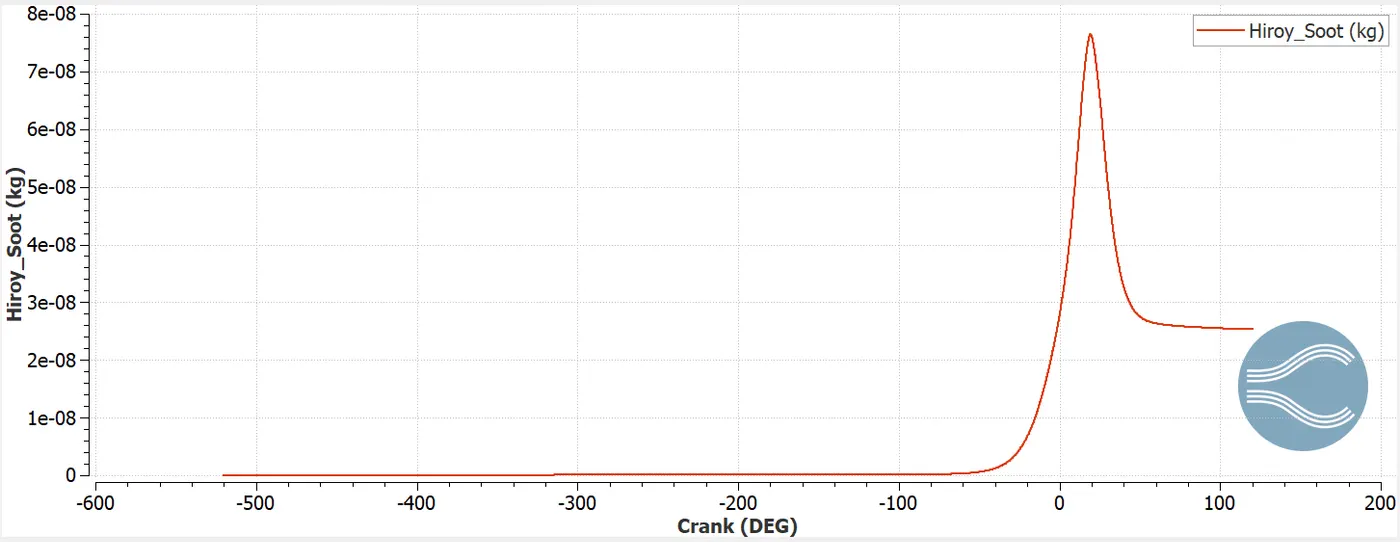
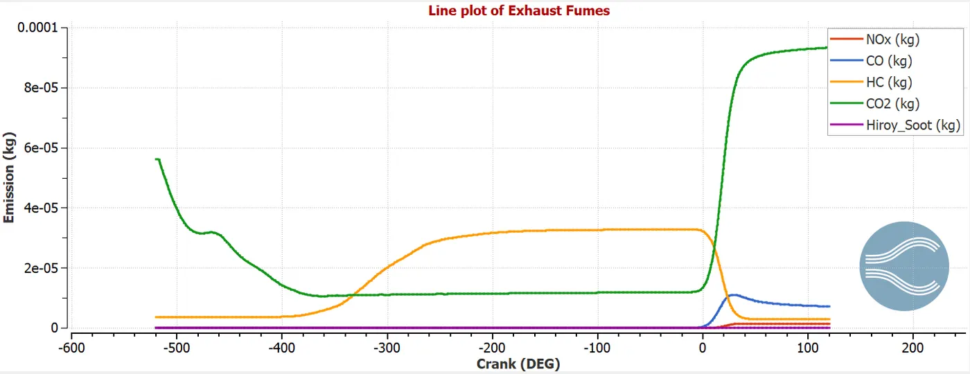
Variation of emission from the engine can be seen from the above plot.Emission consist of different particulate matter like carbon dioxide , carbon monooxide, and unburnt hydrocarbon ,these are formed due to incomplete combustion of fuel. NOX are formed due to reaction of nitrogent To reduce soot NOX and various particulate matter companies are working to improve the quality of the exhaust gases.
Conclusion
The no hydro simulation is carried out to reduce computational time and check mesh quality, valve lift profile.
Then full hydro simulation is carried out for various profile of temperature and spray parcel distribution are observed, various engine performance parameter are calculated.