Week 10: Project 1 - FULL HYDRO case set up (PFI)
AIM
To Perform a full hydrodynamic simulation of a Port fuel injection engine using SAGE combustion model in converge CFD.
Introduction
- The purpose of task is to do boundary flagging and surface preparation for the given geometry.
- After that we will run the simulation for full hydrodynamic case setup and see the motion of piston and valves in cylinder for better understanding.
Objective:
- Simulate a full hydro condition of Port fuel injection engine.
- The objective of this work is to setup Full hydro simulation of IC engine in converge CFD.
- Other work Includes boundary flagging and model setup for no hydro simulation.
1. What is the compression ratio of this engine?
2. Why do we need a wall heat transfer model? Why can't we predict the wall temperature from the CFD simulation?
3. Calculate the combustion efficiency of this engine
4. use the engine performance calculator, to determine the power and torque for this engine.
5. What is the significance of ca10, ca50 and ca90?
GIVEN DATA
Engine Geometric Parameters
- Bore =0.086 m
- Stroke = 0.09 m
- Connecting rod length = 0.18 m
- RPM = 3000
Run parameters
- Simulation mode: No Hydro
Simulation time parameters
- Start time : -520 deg
- end time : 120 deg
Boundary conditions
- Piston temperature - 450K
- Liner temperature - 450K
- Head temperature - 450K
- Spark Plug temperature - 550K
- Spark Plug electrode temperature - 600K
- Exhaust ports temperature - 500K
- Exhaut outflow - 1 bar
- Exhaust outlflow temperature - 800k
- Exhaust species concentration - Calculate the stoichiometric condition
- Exhaust valve top temperature - 525K
- Exhaust valve angle temperature - 525K
- Exhaust valve bottom temeprature - 525K
- Intake port - 1 temperature 425K
- Intake port - 2 temperature 425K
- Inflow pressure - 1 bar total pressure
- Inflow temperature - 363K
- Inflow species - Air
- Intake valve top temperature - 480K
- Intake valve angle temperature - 480K
- Intake valve bottom temeprature - 480K
Initial conditions
- Intake port - 1 (closer to combustion chamber)
- ic8h18 - 0.025508
- o2 - 0.20157
- n2 - 0.77292
- Temperature - 390k
- pressure - 1 bar
- Intake port - 2 (away from combustion chamber)
- Air
- Temperature - 370K
- Pressure - 1 bar
- Cylinder
- Pressure - 1.85731 bar
- Temperature - 1360K
- Stoichiometric composition
Injection Parameters
- Fuel flow rate = 7.5e-4 Kg/second
- Injection start time = -480.0
- Injection duration = 191.2
- Fuel temperature = 330K
Nozzle positions
Nozzle diameter = 250 micro-meter
Circular injection radius = Nozzle radius
Spray cone angle = 10
- Nozzle 0
- center 0.0823357 0.00100001 0.07019
- Align Vector -0.732501 0.210489 -0.647408
- Nozzle 1
- center 0.0823357 -0.00099999 0.07019
- Align Vector -0.732501 -0.210489 -0.647408
- Nozzle 2
- center 0.0823357 -0.0004 0.07019
- Align Vector -0.5 -0.2 -0.647408
- Nozzle 3
- center 0.0823357 0.0003 0.07019
- Align Vector -0.5 0.2 -0.647408
Spark Ignition Parameters
- Start of spark = -15 deg
- Spark duration = 10 deg
- Spark location = -0.003 0 0.0091
- Spark radius = 0.0005m
Modelling the problem in Converge Software
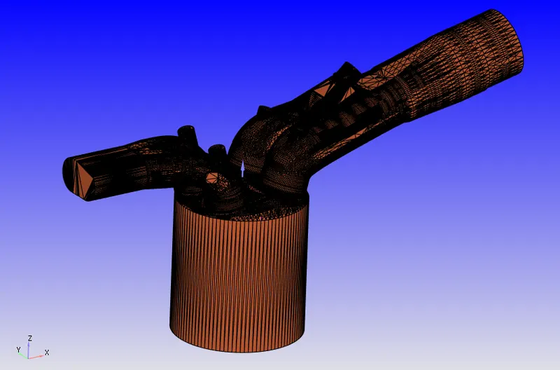
The 3D model is imported in the software.
Case Setup
Application Type- Crank angle-based IC engine
Physical Parameters:
Bore =0.086 m
Stroke = 0.09 m
Connecting rod length = 0.18 m
RPM = 3000
Materials
Gas Simulation- The therm.dat file was uploaded to get the thermodynamic properties of the fuel.
Parcel Simulation- IC8H18 was selected from predefined liquids.
Reaction Mechanism
Species-Parcel IC8H18
Mesh
Run Parameters:
Transient, Full hydrodynamic.
Simulation Time Parameters:
Start time : -520 deg
end time : 120 deg
Boundary Conditions:
Boundary Type-WALL , Wall motion-Translating and Surface-Moving
Law of wall for velocity & temperature boundary conditions
- Piston-Velocity-piston motion, temperature - 450K
- Exhaust valve top temperature - 525K, Exhaust lift profile is imported
- Exhaust valve angle temperature - 525K, Exhaust lift profile is imported
- Exhaust valve bottom temeprature - 525K, Exhaust lift profile is imported
- Intake valve top temperature - 480K, intake lift profile is imported
- Intake valve angle temperature - 480K, intake lift profile is imported
- Intake valve bottom temeprature - 480K, intake lift profile is imported
- Boundary Type-WALL , Wall motion-Stationary and Surface-Fixed
Law of wall for velocity & temperature boundary conditions
- Liner temperature - 450K
- Head temperature - 450K
- Spark Plug temperature - 550K
- Spark Plug electrode temperature - 600K
- Exhaust ports temperature - 500K
- Intake port - 1 temperature 425K
- Intake port - 2 temperature 425K
- Boundary Type-INFLOW & OUTFLOW
Inflow
- Inflow pressure - 1 bar total pressure
- Inflow temperature - 363K
- Inflow species - Air
- Exhaut outflow - 1 bar
- Exhaust outlflow temperature - 800k
- Exhaust species concentration - Calculate the stoichiometric condition
- Regions and Initial conditions:
Intake port - 1 (closer to combustion chamber)
- ic8h18 - 0.025508
- o2 - 0.20157
- n2 - 0.77292
- Temperature - 390k
- pressure - 1 bar
Intake port - 2 (away from combustion chamber)
- Air
- Temperature - 370K
- Pressure - 1 bar
- Cylinder
- Pressure - 1.85731 bar
- Temperature - 1360K
- Exhaust region same as cylinder region
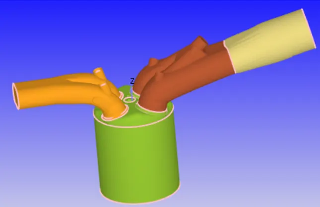
The below figure shows the different regions in the engine.
Events:
Cyclic event is given with exhaust and intake lift profile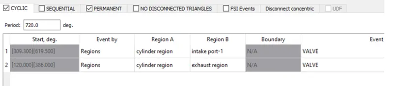
Permanent event is given to intake port 1 & 2 and set to open. 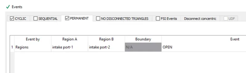
Physical models:
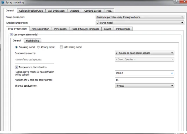
Spray Modelling:
- Forsling model
Collison model-NTC collision, collision outcomes-Post Collison outcomes - Injection Parameters:
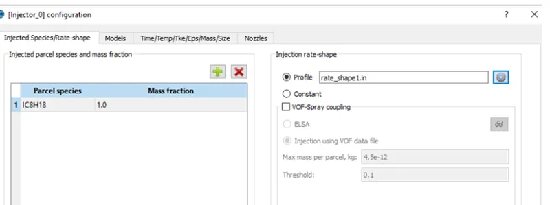
Fuel flow rate = 7.5e-4 Kg/second
Injection start time = -480.0
Injection duration = 191.2
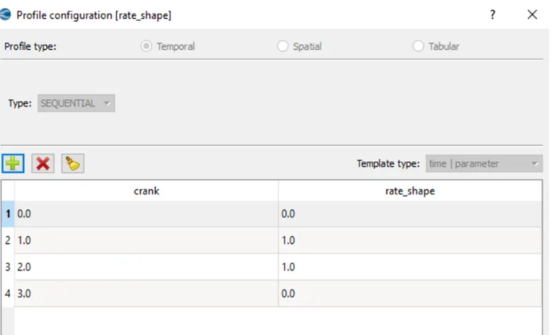
Fuel temperature = 330K - Rate shape implementation:
Nozzle Positions:
- Nozzle diameter = 250 micro-meter
- Circular injection radius = Nozzle radius
- Spray cone angle = 10
Nozzle 0
- centre 0.0823357 0.00100001 0.07019
- Align Vector -0.732501 0.210489 -0.647408
Nozzle 1
- centre 0.0823357 -0.00099999 0.07019
- Align Vector -0.732501 -0.210489 -0.647408
Nozzle 2
- centre 0.0823357 -0.0004 0.07019
- Align Vector -0.5 -0.2 -0.647408
Nozzle 3
- centre 0.0823357 0.0003 0.07019
- Align Vector -0.5 0.2 -0.647408
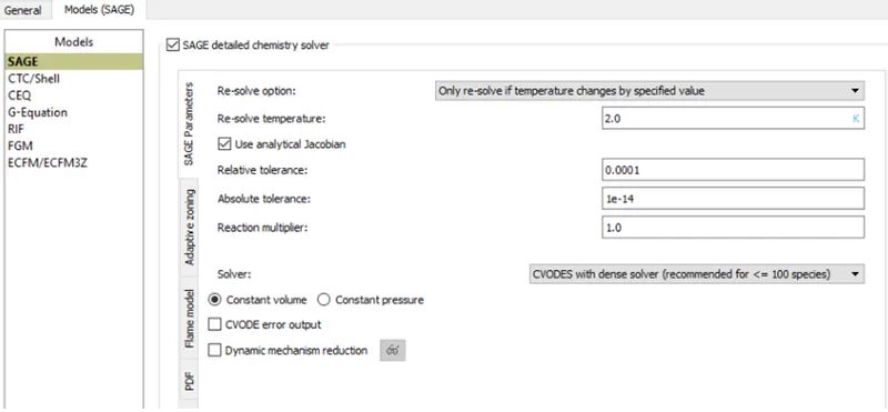
Combustion modelling: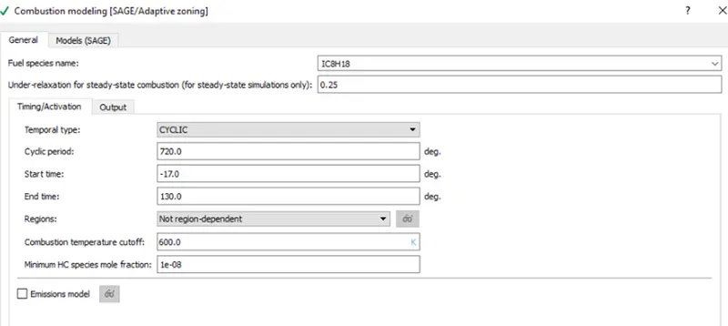
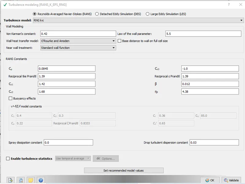
Turbulence Modelling:
RANS k-epsilon RNG model
Spray Modelling:
- 04 J of energy
- Start of spark = -15 deg
- Spark duration = 10 deg
- Spark location = -0.003 0 0.0091
- Spark radius = 0.0005m
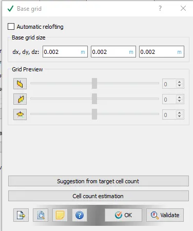
Grid Control:
- Base Mesh- dx=dy=dz=0.002m
Adaptive Mesh Refinement:
- Velocity Adaptive Mesh Refinement
Temperature Adaptive Mesh Refinement: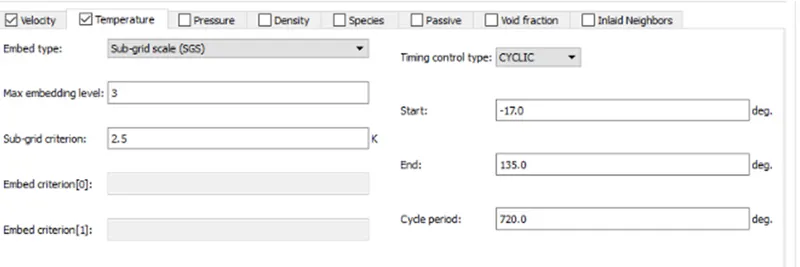
Fixed Embedding:
Boundary Embedding
- Intake valve angle-Permanent, Scale-3, embed layers-1
- Exhaust valve angle-Permanent ,Scale-3, embed layers-1
- Cylinder Embedding-cylinder
- Big Cylinder Embedding-Permanent, Scale-1 ,0.08m
- Small Cylinder Embedding-Permanent, Scale-1 ,0.018m
Spherical Embedding
Spark plug
- Small sphere-Cyclic, Scale-5 ,start time=-16 deg ,end time=7 deg ,radius=0.001m
- Large sphere-Cyclic, Scale-3 ,start time=-16 deg ,end time=7 deg ,radius=0.003m
Injector Embedding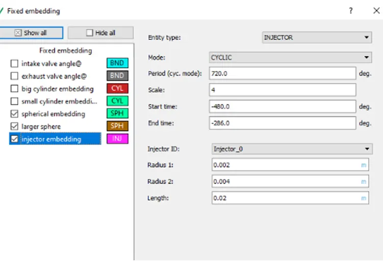
Results
Pressure Vs Crank angle: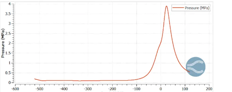
Mass of Liquid parcel present in cylinder at every crank angle:
The below graph shows the amount of liquid drops present at each crank angle.We can see that all the mass has been utilised in combustion and there is no unburnt fuel at the end.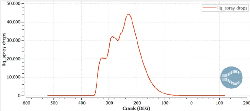
Mass of isooctane present in cylinder at every crank angle:
The below graph shows the amount of IC8H18 present at each crank angle.We can see that all the mass has been utilised in combustion and there is no unburnt fuel at the end.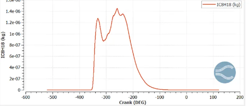
Full Hydrodynamic Simulation
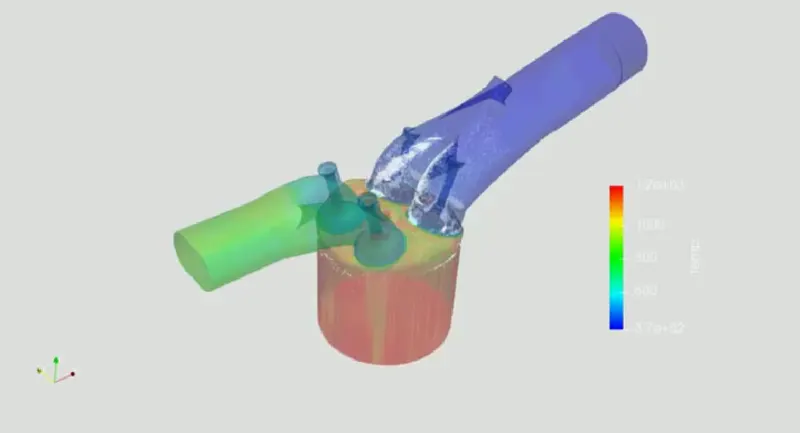
Animation Link : https://youtu.be/M_jfdz3af58
Compression ratio:
Compression ratio is the ratio of maximum volume of cylinder when the piston is at bottom dead center to the minimum volume of cylinder when the piston ia tdc.
From the below graph we can find the maximum and minimum volume of cylinder and calculate the compression ratio.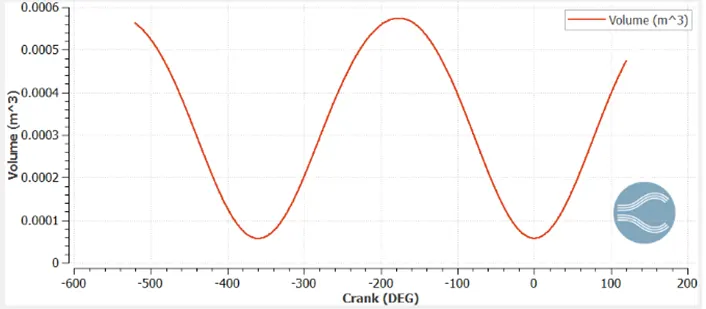
Compression ratio=
=10.02
Where Vc=clearance volume
Vs = swept volume
Why do we need a wall heat transfer model:
Calculate the combustion efficiency of this engine:
Combustion efficiency can be defined as the ratio of total energy released by combustion to the amount of energy contained in the fuel. The energy contained the fuel is called Lower heating value or calorific value.
The below graph indicate the integrated heat released by the combustion process.
Mass of Fuel=3e-5 kg/cycle
Lower heating value of isooctane=43.44 MJ/kg=43.44*3e-5=1303.2 J
Energy released= 1241.15 J
Combustion efficiency=energy released/LCV=1241.15/1303.2=0.952
Combustion efficiency=95.2 %
Power and torque for the engine:
From the engine performance calculator,
Speed =3000 rpm=3000/60 RPS
= 50 revolution/sec
=360*50 degree/sec
Combustion time= 240.199 degree
Combustion time in seconds=240.199/(360*50)=0.0133 s
Now,
Work=468.646 Nm
Power=work/time
Power=468.646/0.0133
Power =
so, T=
=112.2 W
Significance of ca10, ca50 and ca90:
ca10, ca50 and ca90 refers to the crank angle at which 10,50 and 90 percent of fuel is burnt.
From the results the value are,
ca10=6.837
ca50=18.46
ca90= 31.7
Video link:-https://www.youtube.com/watch?v=LMQ05_ve11U
Conclusion:
The full hydro condition of Port fuel injection engine was set and the simulation was run successfully.