Week 10 Challenge
Aim :
1)What all checks need to be followed in design of well foundation regarding the stability and the design. List out all the necessary clauses from IRC codes applicable.
2)What are the limits in ULS and SLS for design of a RCC component. Define the limit states and the factors in it as per IRC 112. Also mention shear checks . what is the difference in shear with/without reinforcement?
3) How to check steining thickness and its steel. What will be the change in PCC and RCC steining.
4) How the spacing of pile is determined in 6 pile system . describe the bulb theory with neat diagrams showing the stress distributions.
5)
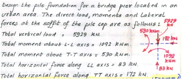
Introduction : Driven cast insitu piles can be assumed . You are free to choose the depth,number and diameter of the pile . Give reactions of atleast two different piles (assuming different pile dia)
Assume spacing as 3 times diameter.
Lateral load to be equally shared by all piles. Vertical capacity as 2000 KN for 1.2 m 1750 KN for 1 m 1500 kN for 0.9 m pile diameter.
Procedure :
1)What all checks need to be followed in design of well foundation regarding the stability and the design. List out all the necessary clauses from IRC codes applicable.
Ans.
Checks to be followed in design of well foundation are as follows:
Base pressure check - Smaller dia of well will have less base pressure & larger dia of well will have more base pressure to provide stability.
Calculation of earth pressure (Active/Passive)
Passive earth pressure to start from MSL (mean scour level)/Liquefaction level
Determining the point of zero shear - It is a iterative process to negate active & passive earth pressures and come to point of zero shear to have maximum bending moment for stability.
Determining the thickness of steining & its stressess.
If steining is cracked, FEM Design or PCC can be given.
IRC codes applicable for checks are as follows:
Base pressure check is performed from load combinations of unfactored loads according to notification no 78, dated 28th July 2012,
ULS design is done using Combination 1 and Seismic Combination while stress is checked using Combination 2 or IRC 6.
Stress & Calculations calculations are as per IRC 112 Cl 12
Crack width is controlled by adjusting bar diameter and spacing calculated.
Earth pressure calculations are as per IRC 6 Cl.214
Design considerations for steining are as per IRC 78 Cl.708.3 & FEM as per IRC 112.
2)What are the limits in ULS and SLS for design of a RCC component. Define the limit states and the factors in it as per IRC 112. Also mention shear checks . what is the difference in shear with/without reinforcement?
Ans. Limits in ULS and SLS for design of a RCC component are,
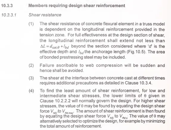
| Ultimate Limit State (For verification of structural strength) |
| Basic Combination |
| Seismic Combination |
| Serviceability Limit State |
| Rare Combination (For checking stress limits) |
| Quasi-permanent Combination (For checking crack width in RCC structures) |
| Combination for Design of Foundation |
| Combination 1 |
| Combination 2 |
| Seismic Combination |
Define the limit states and the factors in it as per IRC 112.
Limit States
States beyond which the structure no longer fulfills the relevant design criteria.
Ultimate Limit States
States associated with collapse or with other similar forms of structural failure.
Note: These generally correspond to the maximum load-carrying resistance of a structure or structural member.
Serviceability Limit States
States that correspond to conditions beyond which specified service requirements for a structure or structural member are no longer met.
Limit State Philosophy of Design
(1) The response of the structure when subjected to different magnitudes of loads lies in different states (domains). 'Limit States' are defined as limits of domains beyond which the structure does not meet specified performance criteria.
In 'Limit State Philosophy' of design, various boundaries of acceptable/unacceptable performance are defined together with the circumstances in which such performances are expected.
(2) Two basic groups of limit states are considered;
(a) Ultimate Limit States (ULS): These limit states cover static equilibrium and failure of structural elements or structure as a whole, when acted upon by 'ultimate design loads'.
(b) Serviceability Limit States (SLS): These limit states deal with the condition of the structure subjected to influence of 'serviceability design loads'. These conditions include level of internal stress, fatigue failure, deflection, damage to structural element such as cracking, and discomfort to users due to vibration.
The structure shall be designed for the following limit states:
Ultimate limit states (ULS)
Limit state of equilibrium
When subjected to various design combinations of ultimate loads the bridge or any of its components, considered as a rigid body, shall not become unstable.
Limit state of strength
The bridge or any of its components shall not lose its capacity to sustain the various ultimate load combinations by excessive deformation, transformation into a mechanism, rupture, crushing or buckling.
Serviceability limit states (SLS)
Limit state of internal stress
The internal stresses developed in the materials of structural elements shall not exceed the specified magnitudes when subjected to combination of serviceability design actions.
The stresses are to be estimated using resistance models to represent the behaviour of structure, as stipulated in the Code.
Limit state of crack control
The cracking of reinforced, partially prestressed, and prestressed concrete structures under serviceability load combinations is kept within acceptable limits of crack widths in such a way as not to adversely affect the durability or impair the aesthetics.
Alternatively, the control of cracking is deemed to be satisfied by following restrictions on amount and spacing of reinforcement.
Limit state of deformation
The deformation of the bridge or its elements when subjected to combination of design actions shall not adversely affect the proper functioning of its elements, appurtenances, and riding quality. Deformations during construction shall be controlled to achieve proper geometry of finished structure.
Limit state of vibration
For footbridges or component of bridges specifically designed to carry footway loading, the direct verification of vibration limits is required , for which specialist literature may be referred. For special types of bridges and their components dynamic effects under action of wind are required to be calculated and verified to be within acceptable limits. Model tests are required under certain circumstances. For other types of bridges, the limit state of vibration under serviceability load combinations is deemed to be satisfied by limiting deflection of elements.
Limit state of fatigue
The bridge or any of its components shall not lose its capacity to carry design loads by virtue of its materials reaching fatigue limits due to its loading history.
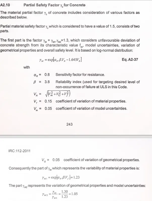
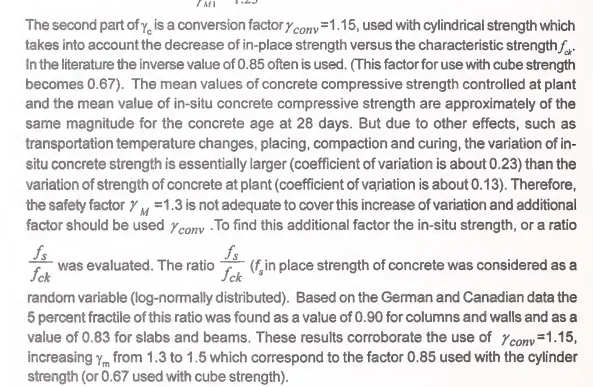
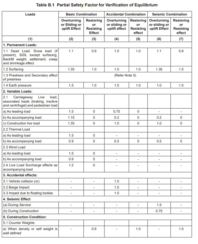
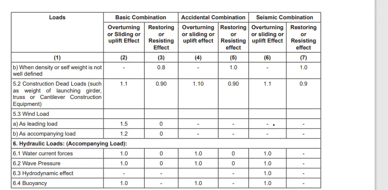
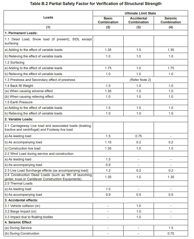
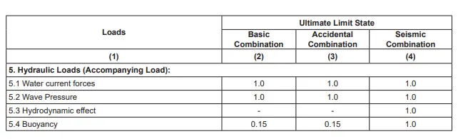
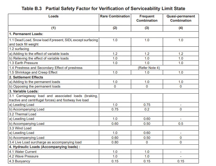
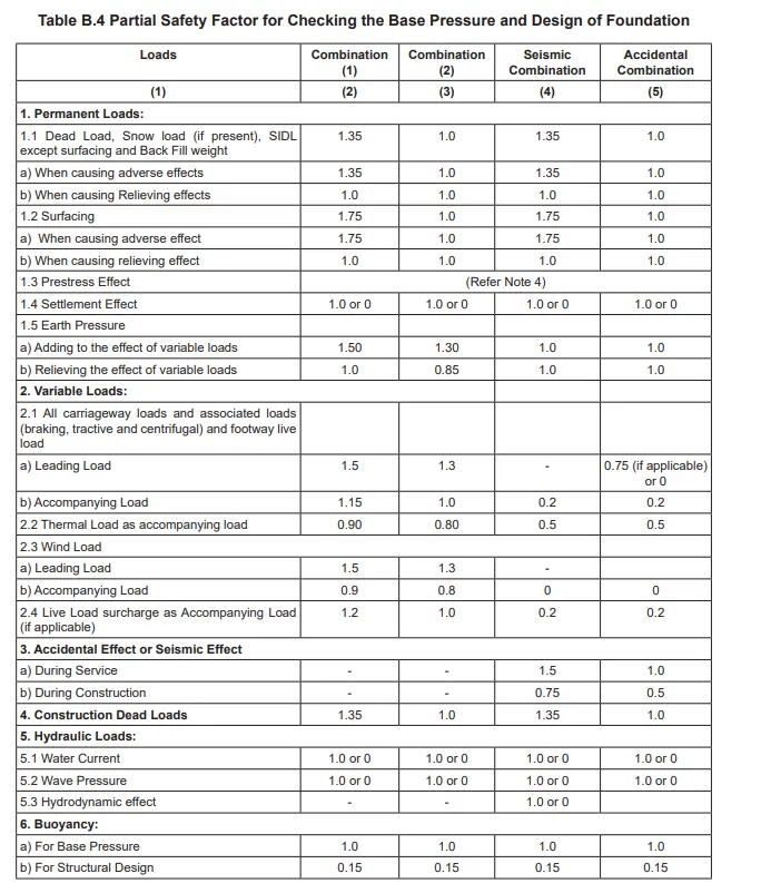
Factors in ULS & SLS as per IRC 112
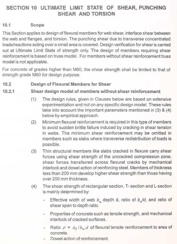
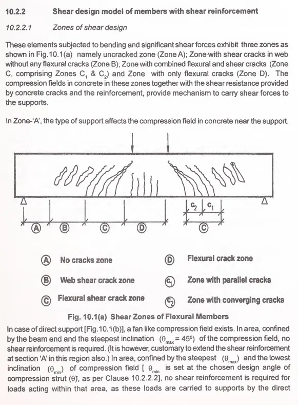
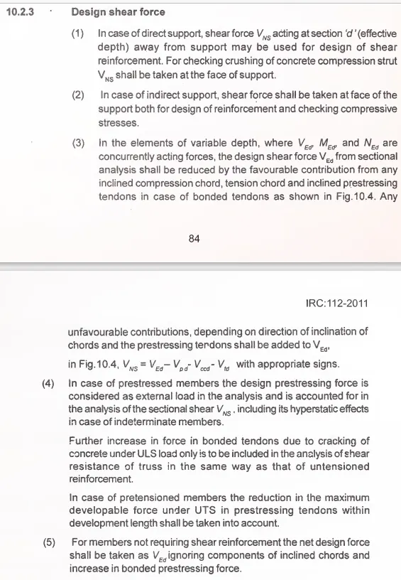
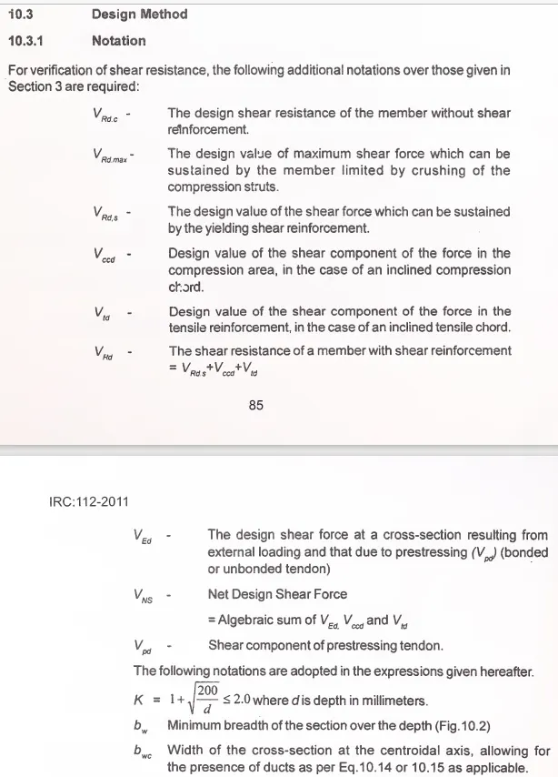
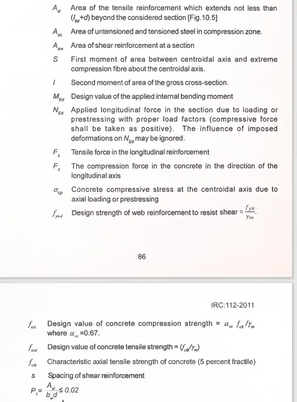
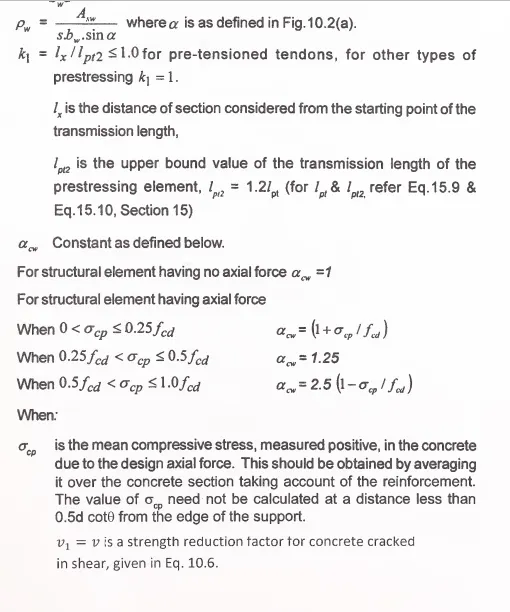
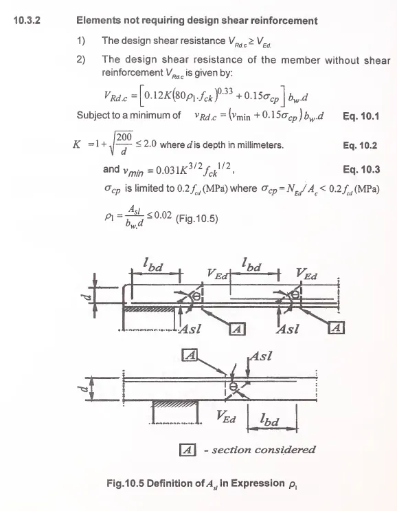
Mention shear checks
3) How to check steining thickness and its steel. What will be the change in PCC and RCC steining.
Ans.
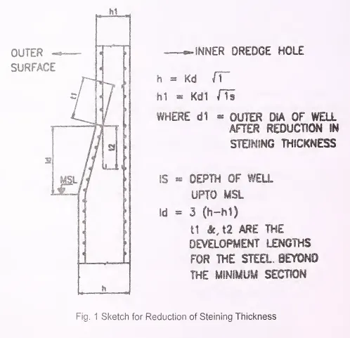
The minimum thickness of the well steining shall not be less than 500 mm and satisfy the following relationship:
h = Kd(/)0.5
h = minimum thickness of steining in m
d = external diameter of circular well of dumb bell shaped well or in case of twin D wells smaller dimension in plan in metres
/ = depth of wells in metre below top of well cap or LWL whichever is more (for floating caisson 7 ' may- be taken as depth of well in metres below bed level).
K - a constant
Value of K shall be as follows:
i) Well in cement concrete K = 0.03
ii) Well in brick masonry K = 0.05
iii) Twin D wells K = 0.039
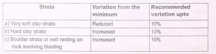
The minimum steining thickness may be varied from above in following conditions:
For plain concrete wells, vertical reinforcements (whether mild steel or deformed bars) in the steining shall not be less than 0.12 percent of gross sectional area of the actual thickness provided. This shall be equally distributed on both faces of the steining. The vertical reinforcements shall be tied up with hoop steel not less than 0.04 percent of the volume per unit length of the steining.
In case where the well steining is designed as a reinforced concrete element, it shall be considered as a column section subjected to combined axial load and bending. However, the amount of vertical reinforcement provided in the steining shall not be less than 0.2 percent (for either mild steel or deformed bars) of the actual gross sectional area of the steining. On the inner face, a minimum of 0.06 percent (of gross area) steel shall be provided. The transverse reinforcement in the steining shall be provided in accordance with the provisions for a column but in no case shall be less than 0.04 percent of the volume per unit length of the steining. The vertical bond rods in brick masonry steining shall not be less than 0.1 percent of the cross-sectional area and shall be encased into cement concrete of M 15 mix of size 1 50 mm x 1 50 mm. These rods shall be equally distributed along the circumference in the middle of the steining and shall be tied up with hoop steel not less than 0.04 percent of the volume per unit length of the steining. The hoop steel shall be provided in a concrete band at spacing of 4
times of the thickness of the steining or 3 metres, whichever is less. The horizontal RCC bands shall not be less than 300 mm wide and 1 50 mm high, reinforced with bars of diameter not less than 10 mm placed at the corners and tied with 6 mm diameter stirrups at 300 mm centre.
4) How the spacing of pile is determined in 6 pile system . describe the bulb theory with neat diagrams showing the stress distributions.
Ans. As per IRC 112 Cl.709
The spacing of piles will be determined by many aspects mentioned above. The working rules which are generally, though not always, suitable, are as follows:
For friction piies, the spacing centre should not be less than the perimeter of the pile or
for circular pile, three times the diameter.
Assuming 1.2m dia circular pile, therefore spacing 3d = 3 x 1.2 = 3.6m, in case of end bearing piles it can be reduced to 2 times dia of pile.
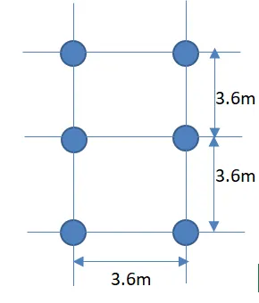
For pile cap offset of 150mm from face of pile has to be given.
Bulb Theory
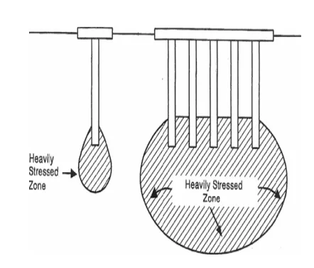
Where pier is supported on multiple piles, connected by frame structure or by solid pile cap, the spacing of piles should be considered in relation to the nature of the ground, their behavior in groups and the execution convenience. The spacing should be chosen with regard to the resulting heave or compaction and should be wide enough to enable the desired number of piles to be installed to the correct penetration without damage to any adjacent construction or to the piles themselves. For land bridges, pier may be supported on single pile having diameter sufficiently large to accommodate construction tolerances of pile installation with reference to location of piers as weil as having strength as required by the design. The pile should be designed to cater for the maximum eccentricity of vertical ioad in such case. Alternatively, pile shaft can be continued to act as a pier and get connected to pier cap which is designed to accommodate the eccentricities due to construction tolerances.
The size of a cap carrying the load from the structure to the pile heads, or the size and effective length of a ground beam, may influence type, size and spacing of piles.
5)
Forces at soffit of pile cap are:
Total vertical = 5929kN
Total moment about L-L axis = 1092 kN
Total moment about T-T axis = 530 kN
Total horizontal force about L-L axis = 83 kN
Total horizontal force about T-T axis = 172 kN
Result:
For 1.2m dia of pile
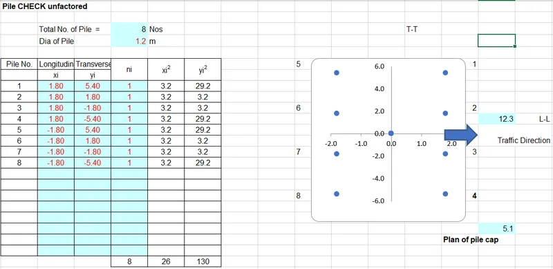
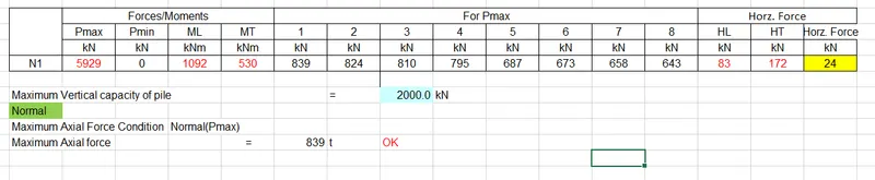
Where vertical force in pile is calculated as:
& Horizontal force in pile is calculated as :
For 1m dia of pile
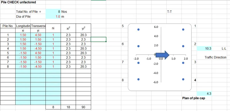
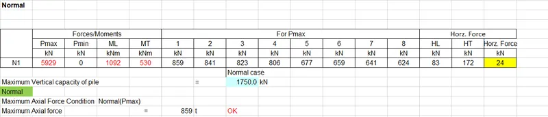
Report is attached as excel herewith.