Week 10 - Challenge 3 - Door Trim Lower with Engineering Features
AIM:
The main aim of this challenge is to create a solid body of 'Door Trim Lower' with the help of the closed surface method by using the 'Generative shape design' workbench in CATIA V5. Performing the 'Draft Analysis' on the solid part body of the Door trim.
CLASS A SURFACE:
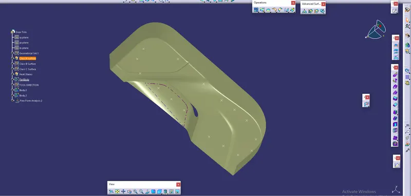
It is surface which is made by the designer. It is aesthetic surface and usable outside futures are on this surface.
CLASS B SURFACE:
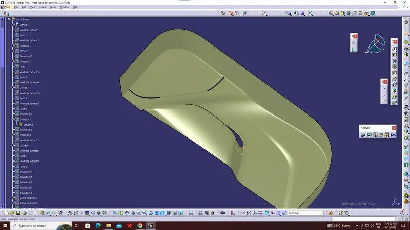
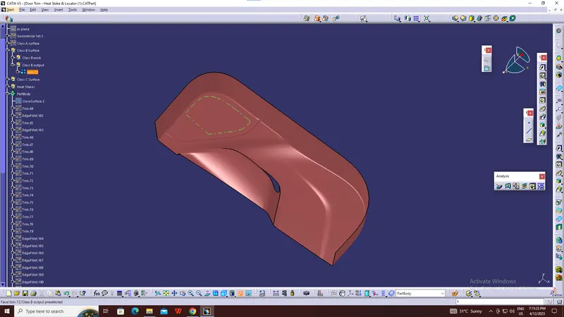
It is bottom side surface of class A surface. It is made by class A surface. It is formed with thickness distance from class A surface.
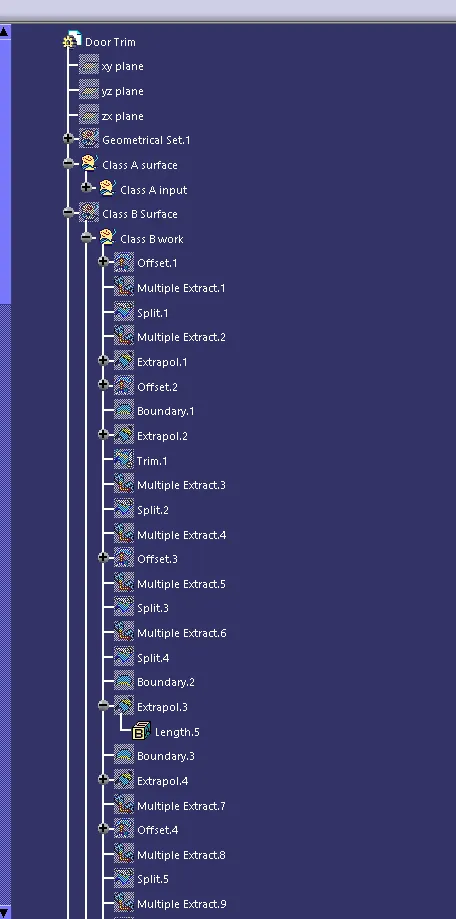
Following procedures are used to create surface B class.
- We directly offset the given bumper surface at 2.5mm distance inside with the help of offset comment fore b surface
- Some discontinuous surface filled with some comment like blend, fill, Mss etc.
- If we need any bounty expand with the help of extrapolated comment.
- Trim unwanted surface
- Finally, we got surface B class.
CLASS B OFFSET
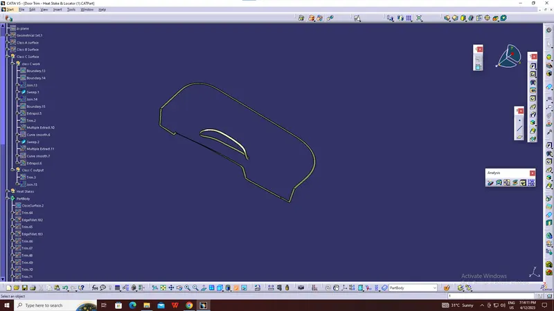
CLASS C SURFACE:
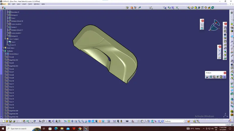
It joins the both class A and class B surfaces. This surface is equal to the thickness of the component.
- Extract tool is used to create the boundary lines separately on side edges of class A surface
- Sweep comment is used to create surface C class for separate edges from given master section reference. Finally merge all sweep surface to get class C surface.
CLASS C OUTPUT
TOOLING AXIS:
- Class A surface or part is used to manually analysis which is best for tooling and create the axis perpendicular to the product. It is called tooling axis. Mould is open and closed by this axis.
- First create the class A surface and manually analysis and fix the direction of tooling.
- In this part two hole on the surface. So, we can directly take its perpendicular as the tooling axis because its most suitable for tooling axis. Carefully watch and take this axis with the help of all types of views.
- First created the point on the surface and create new axis system.

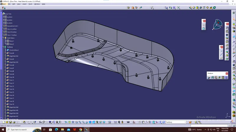
Heat Stakes :
- Heat staking aiso known as thermoplastic staking is the process of joining two dissimilar materials together.
- In heat staking we use local heating and cooling to raise the temperature of plastic components and allow piastic reforming to be carried out.
DRAFT ANALYSIS
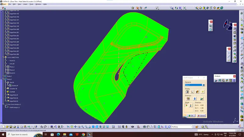
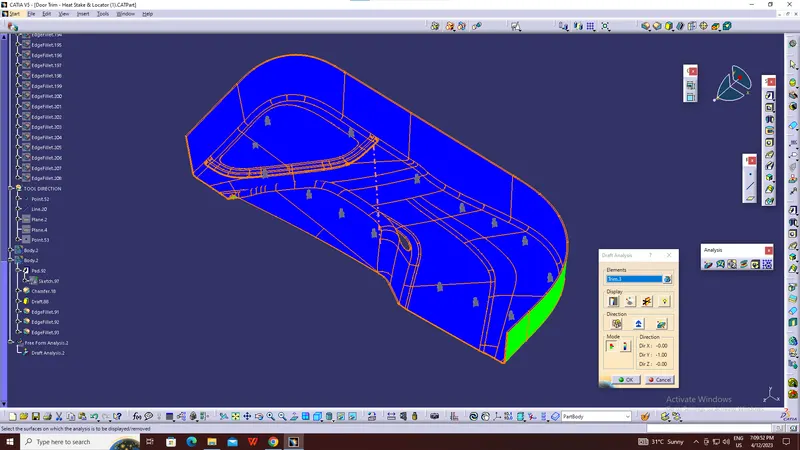
The Draft Analysis is a command that enables you to detect if the part you drafted will be easily removed. This type of analysis is performed based on colour ranges identifying zones on the analysed element where the deviation from the draft direction at any point, corresponds to specified values.
Draft analysis is done after determining the tooling axis, draft analysis is used to check whether the minimum draft (3 degrees) is maintained or not.
- Procedure for performing the draft analysis are as follows
- Change the view mode of the component to be in customized parameter mode and then select the shading mode as materials.
- Then open the featured draft analysis tool from the insert menu
CLOSED BODY
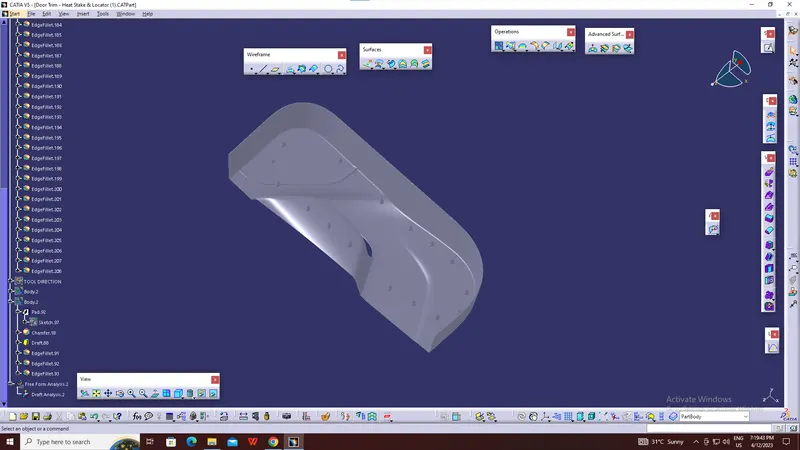
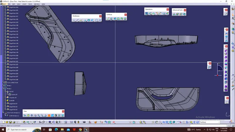
(Isometric, Front, Side, and Top View)
Iso-Constrained
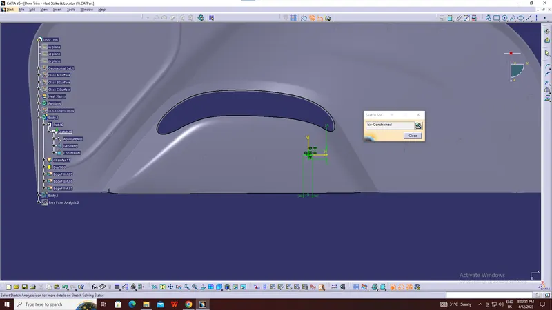
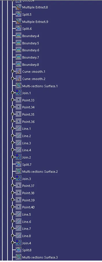
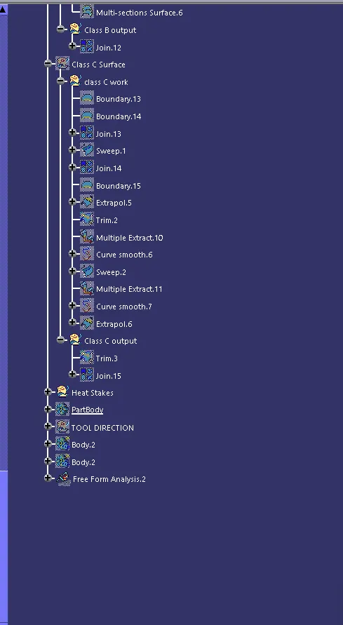
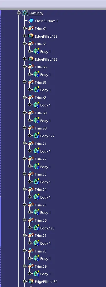
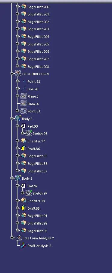
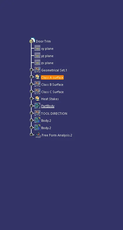
Tree Structure