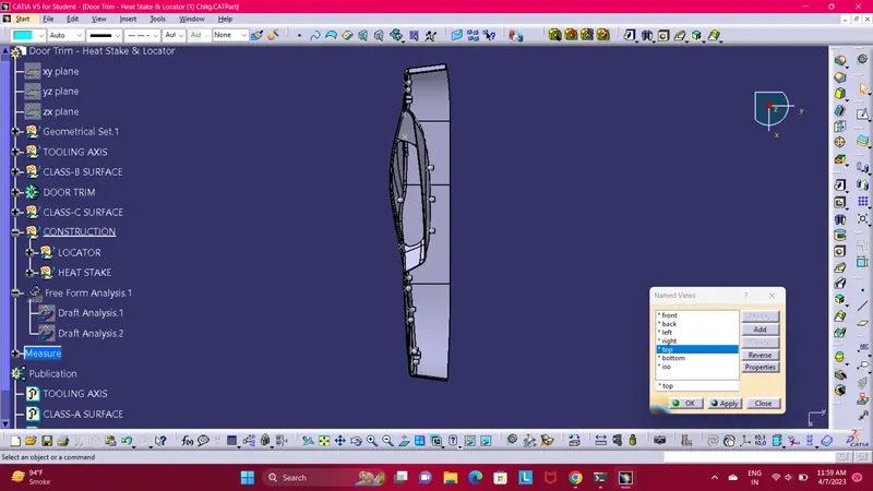
Week 10 - Challenge 3 - Door Trim Lower with Engineering Features
Challenge 3 - Door Trim Lower with Engineering Features
- Report
- A detailed report should be done explaining the draft analysis and the tooling axis creation.
- An explanation should be given on the way of creating the tooling axis, particularly the Bisecting method.
Here i explain in brife about tooling axis creation.
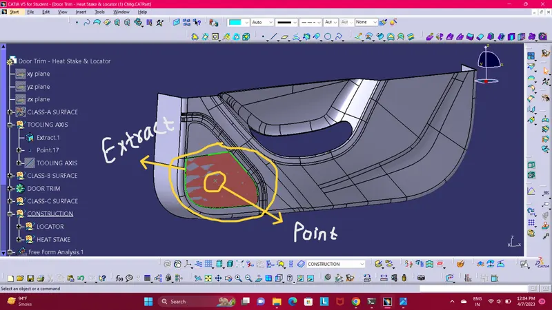
- To creating the tooling axis we use Normal to Surface method. First extract the flat surface of the Door Trim Lower model then create a point on extracted surface. As shown in below image in light brown colour.
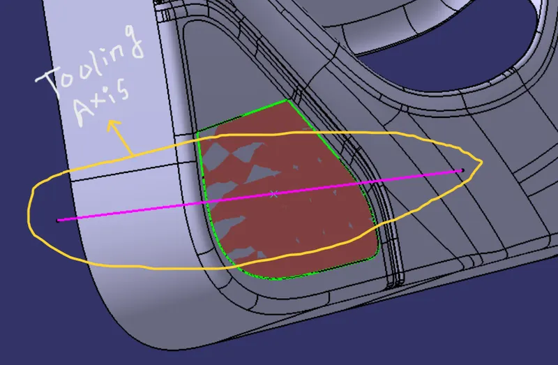
- Now create a aixis on that point using Axis System Command. And here in below image shown the Tooling Axis.
And here i explain in brife about draft analysis creation.
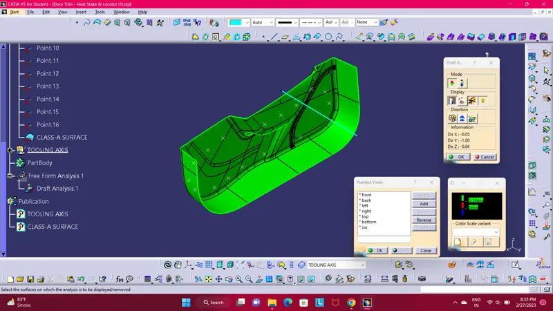
In the above image we are able to see the draft analysis of class-A surface. With the help of draft analysis command we can easly make draft analysis.
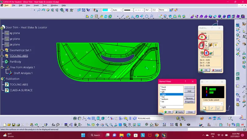
First apply a draft analysis command. From mode section choose first option as shown in above image highlight in red circle., then in display opt allow first opt to activate show/hide colur scale,
and the in last direction opt select the second opt compass then use fit all in command so you are able to see the compass as show in below image highlight in yellow circle.
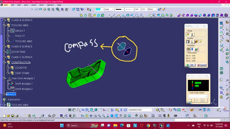
Compass
Then drag the compass to tooling axis and align to tooling axis line. Below the show alignment of compass and tooling axis image
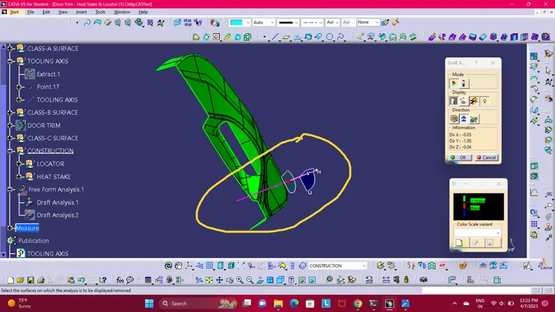
Compass Align to Tooling Axis
- Below images/screenshots should be inserted into the challenge box.
- Screenshots of the completed design in various orientations (Isometric, Front, Side, and Top View).
- Screenshots of the completed design in various orientations (Isometric, Front, Side, and Top View).
- ISOMETRIC VIEW.
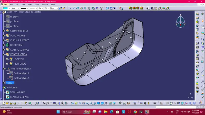
- FRONT VIEW.
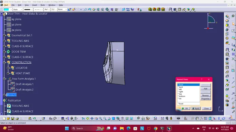
- SIDE VIEW.
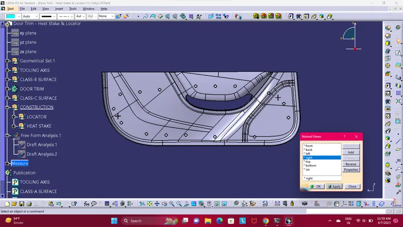
- TOP VIEW.