Week 10 - Challenge 3 - Door Trim Lower with Engineering Features
AIM:
- To create the Door Trim Lower Plastic component through the given Class-A surface
- To create the Heat Stakes and the locators considering the design rules mentioned in the video for the door
OBJECTIVES:
- Sketches
- Use Positioned sketch
- Sketches should be Iso-Constrained
- References
- Use the given points in the model to create the locators and Heat stakes
- Refer to the below-given image for more details
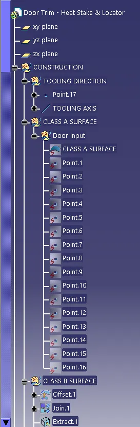
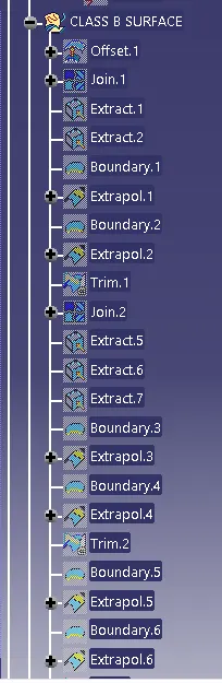
- Tree Structure
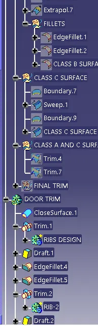
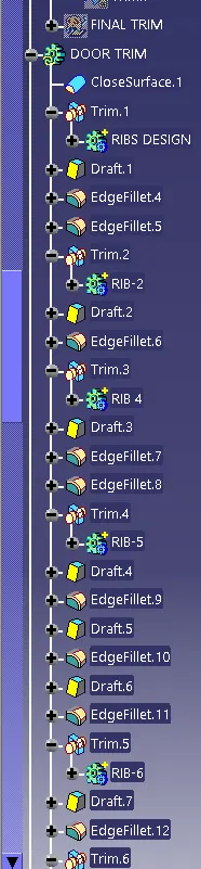
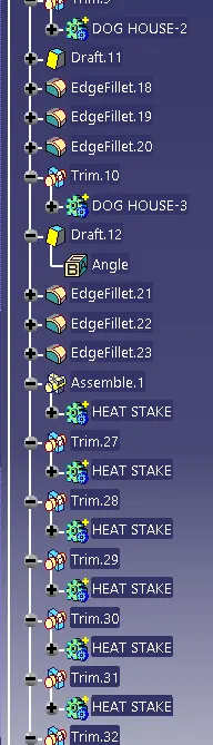
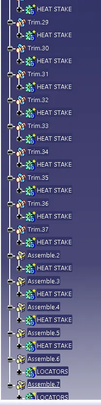
- Ensure Proper Tree Structure
- Geometrical sets should have a proper name based on the sketches present inside of it
- All the sketches should be created under the Geometrical set
- Report
- A detailed report should be done explaining the draft analysis and the tooling axis creation.
- An explanation should be given on the way of creating the tooling axis, particularly the Bisecting method.

REPORT:
DRAFT ANALYSIS:
Draft analysis is done after determining the tooling axis,draft analysis is used to check whether the minimum draft 3 degree is maintained or not.Compass is used to define the draft direction if the minimum draft 3 degree is provided the whole component changes into green colour.
CLASS B SURFACE:
class-B surface is created by extracting each walls and un-trimming and extrapolating the walls to obtain the shape by trimming the excess surfaces and offsetting it to certain distance based on the thickness of the model.The offset surface will be the B-surface.
CLASS-C SURFACE:
The surface created using sweep command by sweeping the boundaries of A-surface along the tooling axis to connect from A to B-surface is nown as C-surface.Using the B and C surfaces created a closed surface will be formed by trimming the excess surfaces the surface will be converted into a solid model using closed surface option.
1) It is a tool that allows the user to ‘see’ whether the part they are designing can be removed from the tool being used to make it.
2)In the case of plastic injection molded parts it also allows the designer to see if there is enough draft on the part to ensure that it can be correctly grained.
3) we always use the tool with the axis direction method. Put the main axis on the draft direction line with Z being parallel to it. Select the tool then select the part body. You may need to reposition the axis again.
4) The results window has 2 options 1 with just 3 colour variants and the other with many variants. They can be edited by double clicking on them to give you the result you desire. The colours show the different draft angles.
5) We have to use following path for drafting anaylsis
Tools- Anaylsis- Feature draft anaylsis
6) At starting of drafting anaylsis we have to set compus which is show in direction row (2nd number option). During this w of compus is set towards the drafting angle.
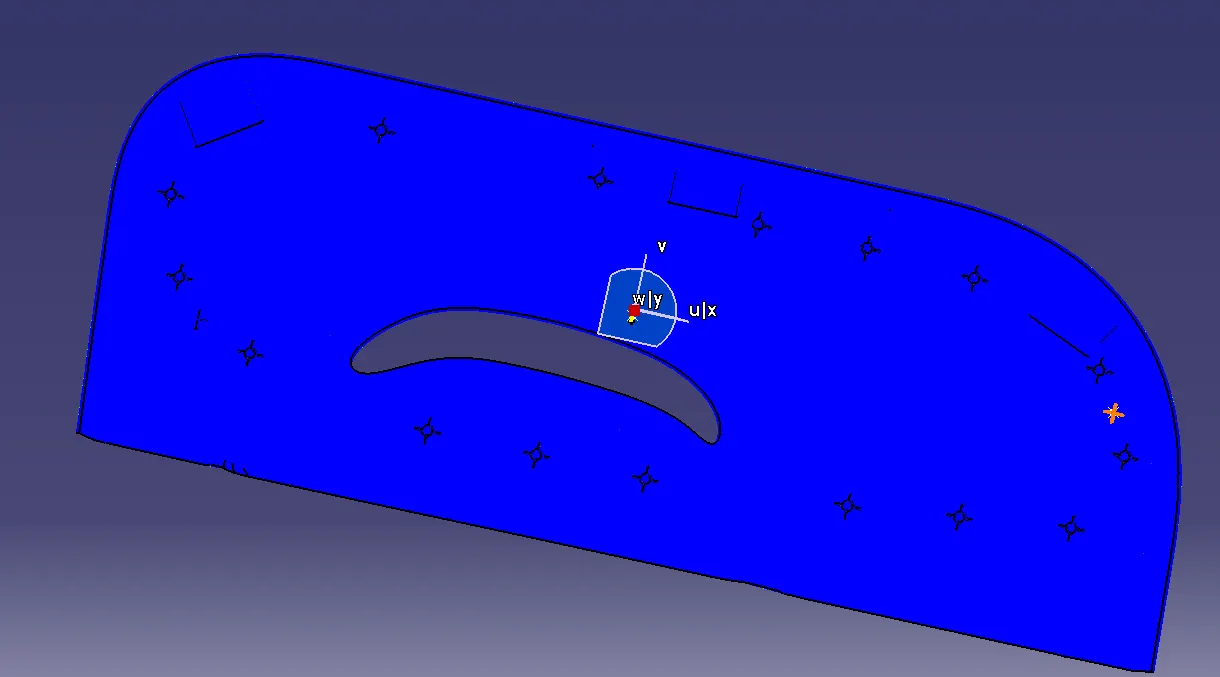
7)After this we have to click on component. Now component become green as shown in below image and also if it become blue then flip direction of compus using flip option in direction row.
8) Finally set drafting angle at 0.5 degree and measure drafting angle at different faces of component by using display row.
9) If your component is green then drafting anaylsis process is completed.
Draft analysis is done after determining the tooling axis,draft analysis is used to check whether the minimum draft 3 degree is maintained or not.Compass is used to define the draft direction if the minimum draft 3 degree is provided the whole component changes into green colour.
CLASS B SURFACE:
class-B surface is created by extracting each walls and un-trimming and extrapolating the walls to obtain the shape by trimming the excess surfaces and offsetting it to certain distance based on the thickness of the model.The offset surface will be the B-surface.
CLASS-C SURFACE:
The surface created using sweep command by sweeping the boundaries of A-surface along the tooling axis to connect from A to B-surface is nown as C-surface.Using the B and C surfaces created a closed surface will be formed by trimming the excess surfaces the surface will be converted into a solid model using closed surface option.
TOOLING AXIS:
STEP 1:
connectivity of class-A surface:First checking the connectivity of the class-A surface,this can be done by creating boundaries or by using the join command and see how well it is connected.Just ensure there is no surface gap between component or surfaces.This is the first design step to check continuity and the quality of the class-A surface.
STEP 2:
Analyse visually for the best possible tooling axis for the component.Checking possibilities in all three x,y and z axis direction and finding what are the problem creation parts of the component.
The clearance checking along all the axis directions will be done by creating an intersection along an axis on plane with the model and constructing two lines contact with the walls,the lines bisecting the two lines and passing through the point will be tooling axis.
CREATION OF TOOLING AXIS:
Using the intersection,lines will be created along the inclined walls and as there is only one wall another line will be created at a certain angle to the wall,these lines are used for creation of tooling axis by bisecting method where the two lines and point will be selected as inputs.
Using the intersection,lines will be created along the inclined walls,these lines are used for creation of tooling axis by bisecting where the two lines and point will be selected as inputs.
Using the tooling axis created along x and y-axis,these are used for creation of tooling axis by bisecting method where the two lines and point will be selected as inputs.
publication is used to make easily accessible of the published components.
Class A surface: Class A surface is a Styling surface or aesthetic surface get it from the styling team. we will design the plastic component by using the Class A surface as input.
- Check all the views of the given class A surface that can help us to understand and get more understanding of the component.
- Connectivity of the class A surface that there is no gap between the component, by using joining command or boundary command we can check.
CREATING THE CLASS B SURFACE
- Class B surface is to be creating the engineering features and offsetting the surface of class A. Firstly we will extract surfaces by using the extract command and from the class A surface. And if there are any patches we have to make it a smooth surface and finally get the complete boundary.
CREATING THE CLASS C SURFACE
- Class C surface is connected the Class A and Class B, For the class C surface, we need to create the entire boundary of the component by using the boundary command.
- And also creating the best way for the tooling direction to manufacturing easily in an effective way.
- By using the sweep command we can combine them and trim the surfaces so we can get the completed closed surface body and draft angle given as min 3 degrees.
- Before trimming the most important things join them all.
- After the body has to be closed by using the closed surface in part modeling.
TOOLING DIRECTION & BISECTING
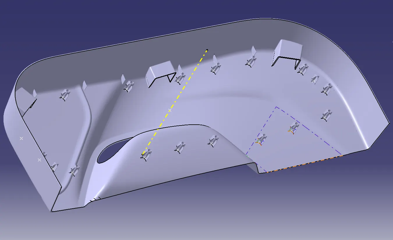
- The tooling direction would be at the axis at that direction it is very easy to manufacture and all the and all faces and the entire surface are to be covered in that direction without adding any other equipment.
- Bisecting, the articular surface is a tool or not we intersect the surface with the respective plane and get a sketch which consists of two lines, and with the help of bisecting line option, we bisect the line which creates a line at the midpoint of the two lines. Likewise, we create a tooling clearing axis for x and y which will be used to create the main tooling axis using the bisecting line option in the line command.
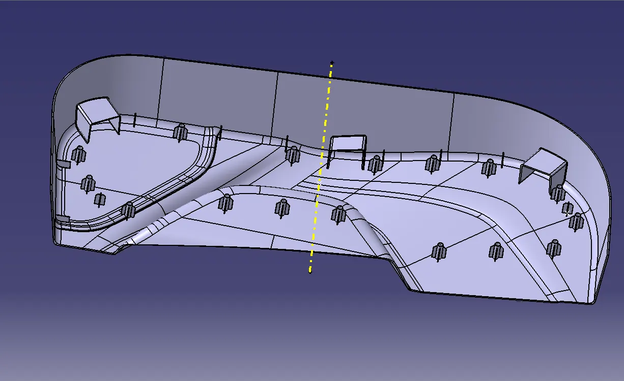
VARIOUS ORIENTATIONS OF THE FINAL COMPONENT
FINAL COMPONENT
DRAFT ANALYSIS
Draft Analysis for the CLASS A SURFACE:
Draft Analysis for the Final Plastic body:
Draft Analysis for final component with engineering features:
DESIGNING OF THE DOG HOUSE
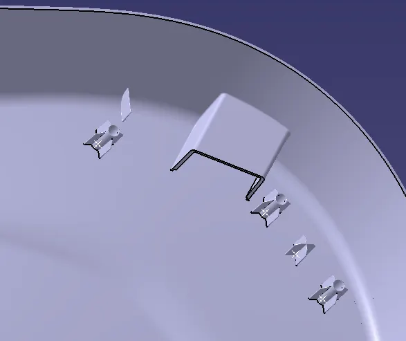
The dog house is an engineering feature used in the plastic trim design. Dog houses are used as supporting features. Sometimes other engineering features like snaps; locators, etc. are mounded on them to increase their strength.
- The dog house is mostly used in automotive plastic and its main purpose is to help to avoid sink marks and saver of wall thickness
There are many design factors considered in to design of a dog house:
Doghouse wall thickness at the intersection of the part wall ( C ) should be 40% or less than the main wall stock ( T ).
The height of ( B ) should be between 3.0 – 6.0 mm
- Extract the base of Class A Surface and offset it with a part thickness of 2.5 mm.
- Draw a sketch of the open rectangle and extrude the rectangle at some height of 30 mm.
- Close the upper surface face by offsetting the below-extracted surface and then after trimmed it.
applying part thickness as 2 mm. - Give the draft to the inside surface of 0.5 degrees.
- Now to create the C and B sections as shown in the design rules, offset the base surface between 3 to 6 mm.
4 WAY LOCATORS & HEAT STAKES:
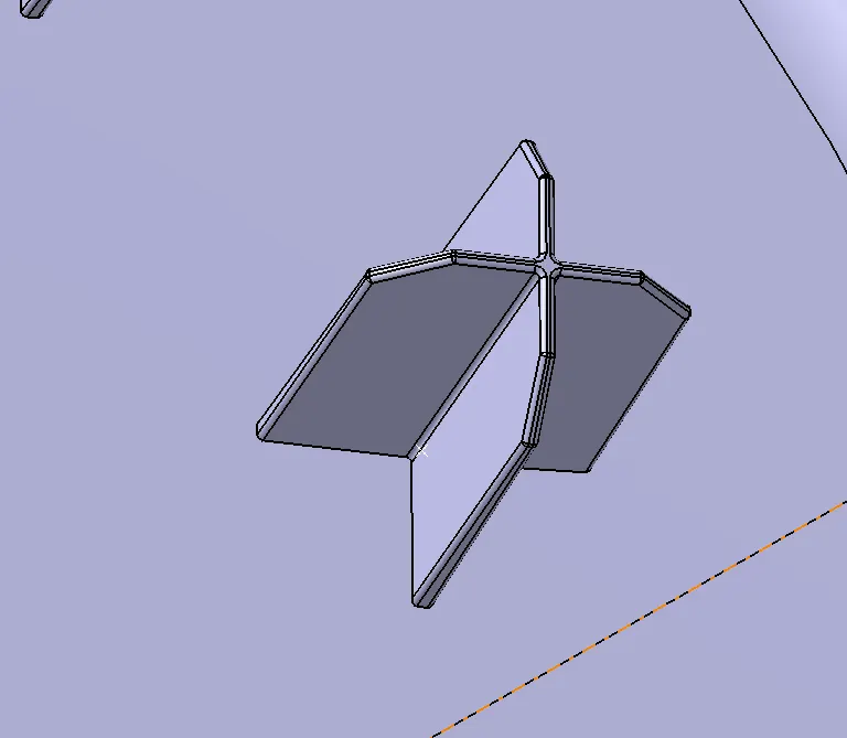
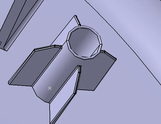
- To create the locators, create a sketch of the body. After creating the sketch, I pad it some height and thicken it, and drafted it with 0.5deg in the direction of the tooling axis. I gave 4 mm of chamfer with 45deg of inclination and after I gave a fillet of 0.25mm radius.
- Heat stakes are most commonly used in automotive industries to jin the plastic to dissimilar materials. Heat staking is an assembly method that can be controlled the melting and reforming of plastics stud or boss to capture or lock another material like plastic or metal components.
FRONT VIEW
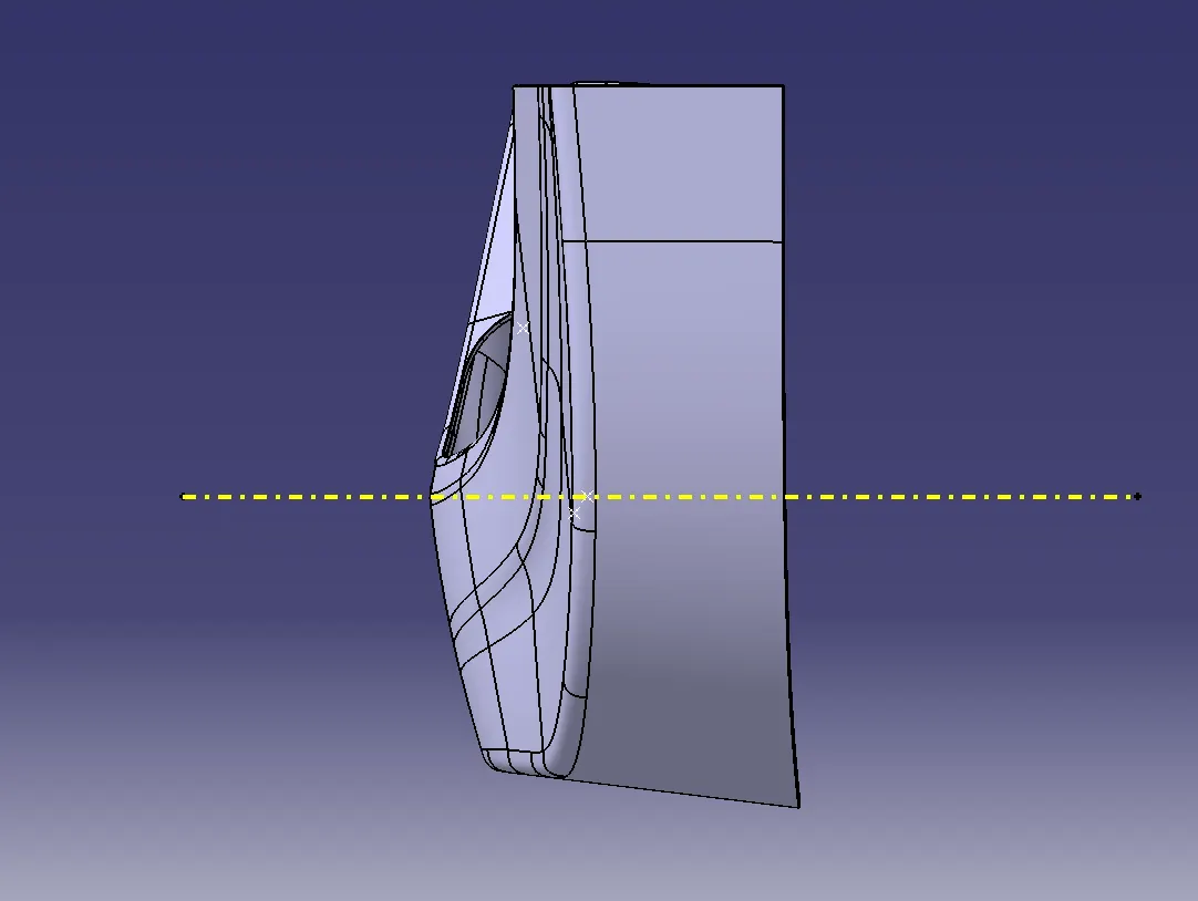
SIDE VIEW
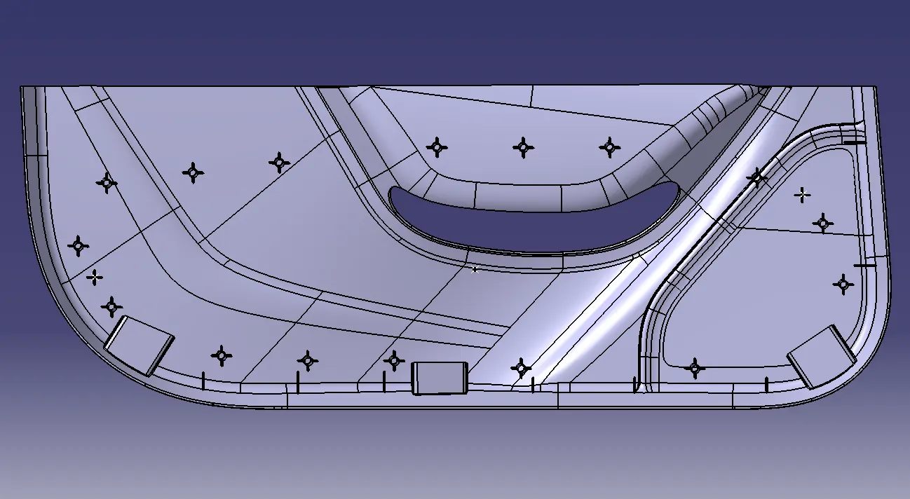
TOP VIEW
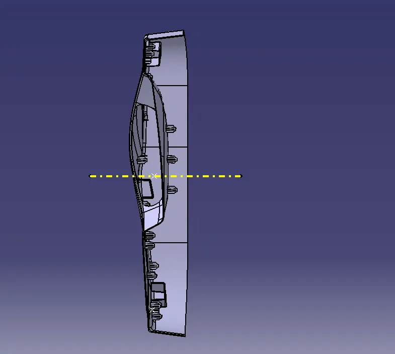
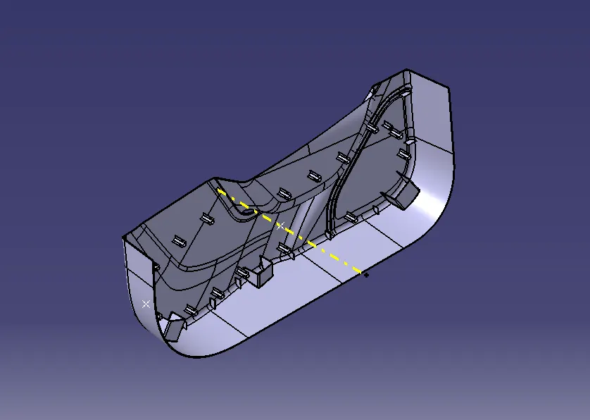
ISOMETRIC VIEW
TREE STRUCTURE
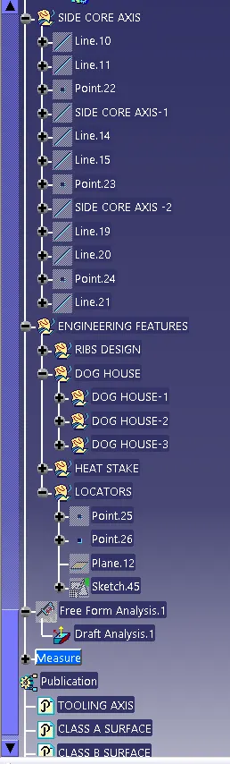
CONCLUSION: Finally the DOOR HANDLE component has been created through the given Class-A surface, with the dog house. locators following the design rules, with the tooling axis for the given Class-A Surface, created meeting the requirements of the draft angle and at the end performing the Draft analysis on the model.
CAT part size is large about 32 MB so I am submitting zip file. please extract file and see.