Week 10 - Challenge 3 - Door Trim Lower with Engineering Features
Door Trim Lower with Engineering Features.
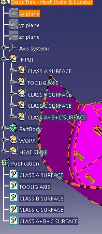
Part Tree.
Tooling Axis.
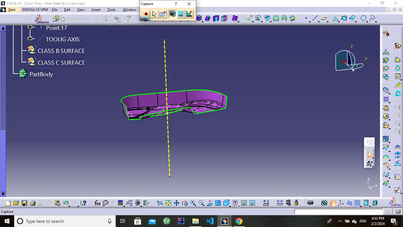
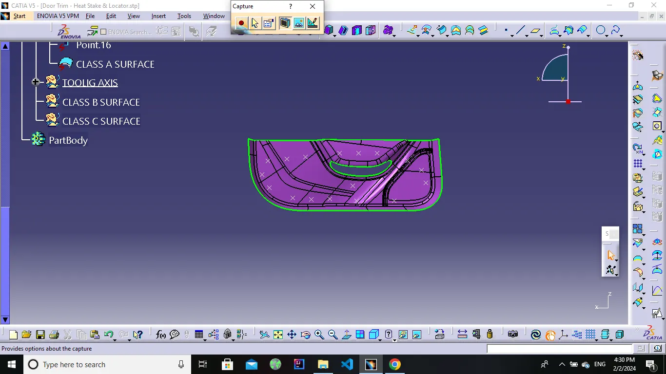
First create a tooling axis for the given class A surface .In this direction the mold opens and closes .
For the given class A surface Y direction is consider as the tooling direction.Then create tooling direction clearing X and Y direction.finally bisecting this two lines to get the main tooling axis.
Class B Surface.
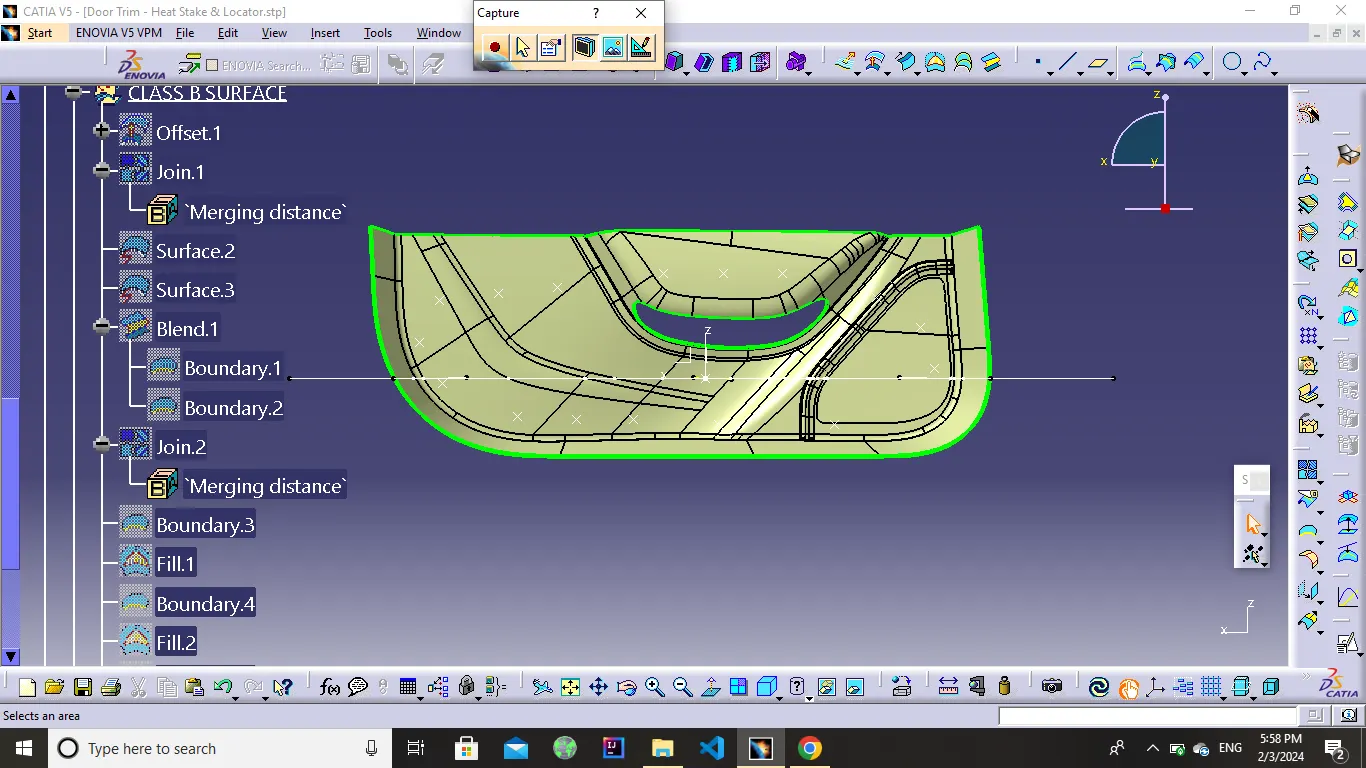
here we just offset the Class A surface and get the B surface body here we offeset the 2.5mm value so we get the thickness is 2.5mm is mention in above so we offset the A surface for 2.5mm.after the offset we get the surface but in that some impurities some portion not offset so we required to solve it so used explore, multiple extract, fill, curve conect, join command and get desire output mobel no any discontinuty than color it so we get B surfaces .
Class C Surface.
c surface creation by using the sweep command so 1st we create a boundary than disassemble get two curve 1st out-side surfaces than second is in-side surfaces after that we used sweep commat in that go to draft section on choose surface reference option and sweep it similar think done inner curve than we get c surface.
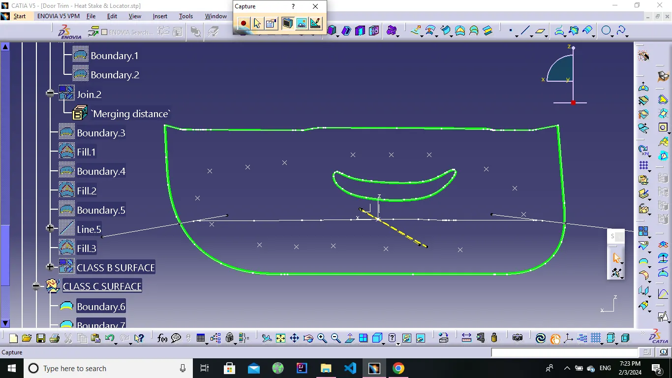
Joinning of Class A B & C.
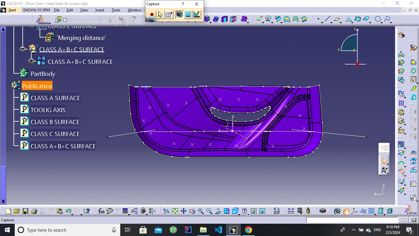
Final Plastic.
Final Plastic get the by trim final surface of c class shown in above image with the b class surface in that we required condition to properly trim it so we used extrapolare command and extrapolare B surface required dimension same think done both inner and outer curve than trim it get close surface
after that we get solid body by using close surface command on part design section
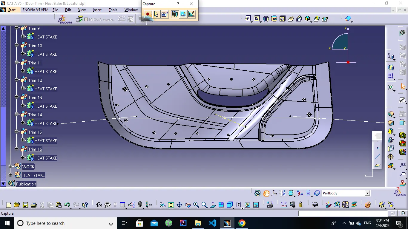
Heat stakes.
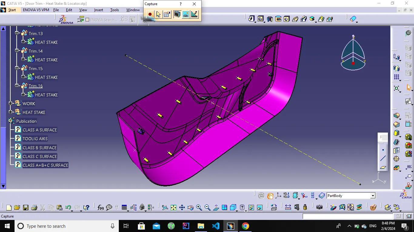
Heat staking also known as thermoplastic staking is the process of joining two dissimilar materials together. In heat staking we use local heating and cooling to raise the temperature of plastic components and allow plastic reforming to be carried out. This reforming can be used in a wide variety of applications.
Thermal staking should be considered when the parts to be assembled are still in the design stage. Several configurations for boss/cavity design are available, each with specific features and advantages. Their selection is determined by such factors as type of plastic, part geometry, assembly requirements, machining and molding capabilities, and cosmetic appearance. Heat staking can be performed using wide range of thermoplastic materials including polypropylene, ABS, polycarbonate and many others.
The integrity of a thermal staked assembly depends greatly upon the geometric relationship between the boss and the thermal tip. Proper design will produce optimum strength with minimum flash.Here heat stakes created with draft 0.5 degree, fillet radius is 0.25mm and wall thickness is 1.5mm (0.6*2.5) .heat stakes designed by following the design rules.
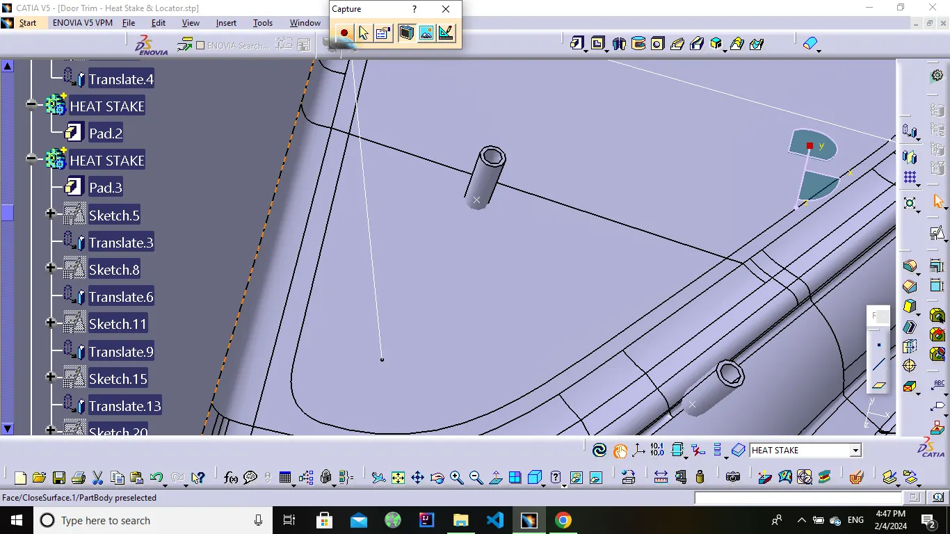
Locators.
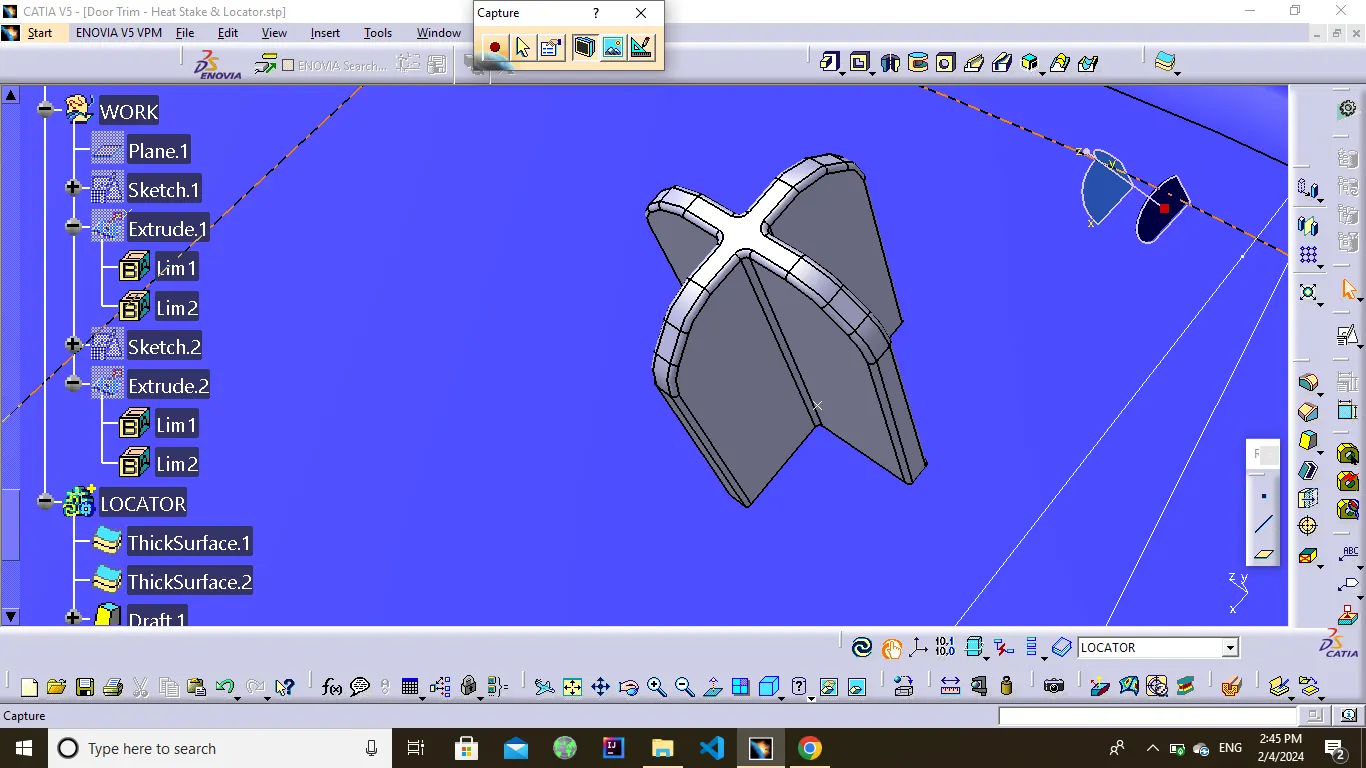
Typically, locating pins are used for controlled, fine tolerance positioning of a work piece.
A 2-way locating pin restricts motion along 1 axis (or 2 degrees of Freedom), like a round pin in a slot. Likewise, a 4-way pin restricts 4 degrees of freedom along 2 axes. A round locating pin located concentrically in a hole is a common application of a 4-way pin, and helps to further secure the piece.Here 4-way locator created with thickness 1mm ,draft 0.5 degree and the fillet value is 0.25 mm .
Final Solid.
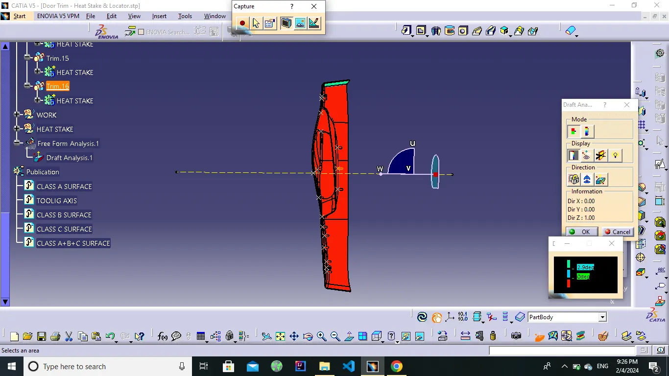
Draft Analysis.
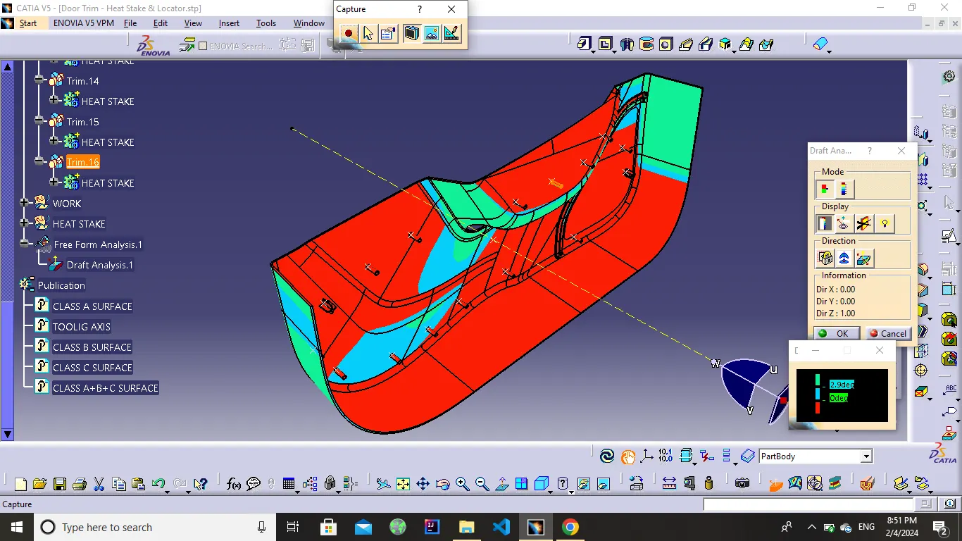
The Draft Analysis allows the user to easily analyze a part for proper draft angle. A Draft Angle describes the amount of taper for molded or cast parts perpendicular to the parting line.We have 2 modes on the draft analysis Quick & Full analysis respectively.Under the Display option we have Show are hidden the Color Scale, Analysis under the running point, No Highlight representation & Light effect.Under the Direction option we have lock or unlock the direction, Compass & Invert.So According to the practical Usage there Should be 1 to 3degree of angle mostly acceptable, by considering these option we have to test our given & Final Components Draft analysis.
Class A Surface.
Final Solid.
Isometric view.
Front view.
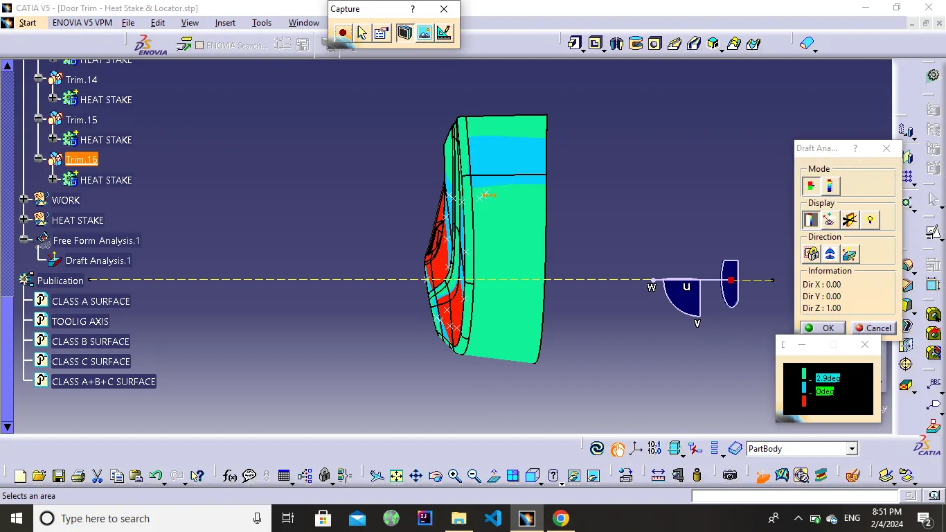
Side view.
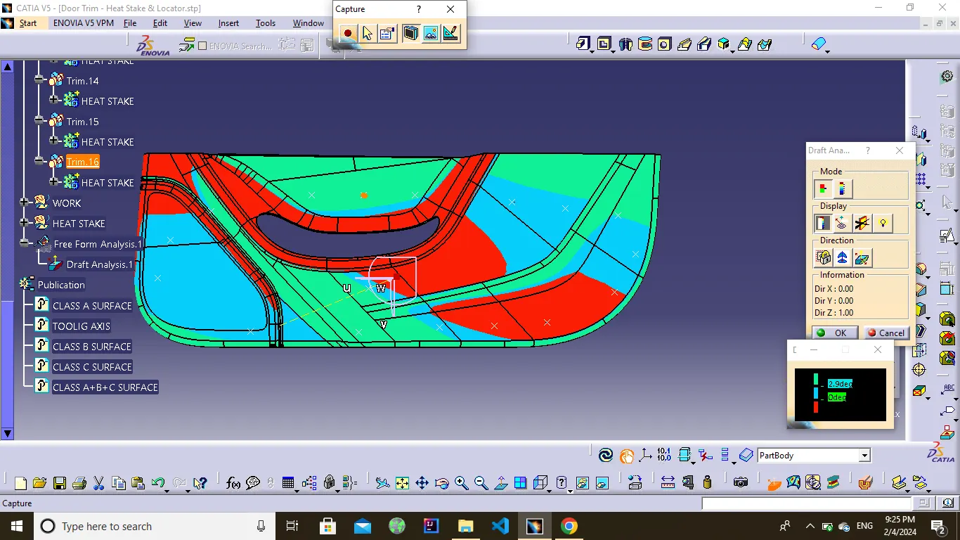
Top View.