Week 10 - Challenge 3 - Door Trim Lower with Engineering Features
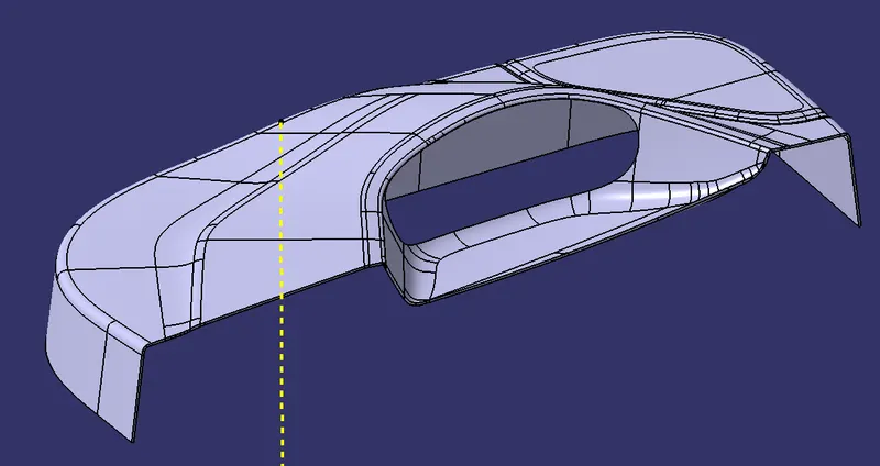
AIM :- Create the Door Trim Lower Plastic component through the given Class-A surface. Also to create heat staking and locators considering all the design rules.
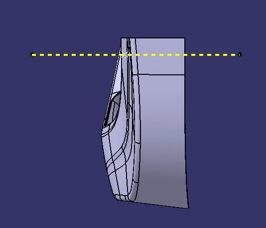
Tooling Axis :- Class-A surface is first analyzed to create the tooling axis. where the molds pull apart in injection molding. Tooling direction is essential for plastic product design as it decides the direction for mold separation.
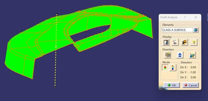
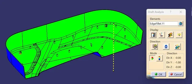
To create the tooling axis first we have to check the best suitable direction for tooling by using the compass. the y direction is suitable for creating the tooling axis because in the y direction most of the surfaces are clearing while performing draft analysis. Generally tooling axis is created using bisecting line method but here A line normal to the surface is created in the y direction and considered the tooling axis.
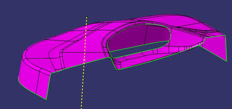
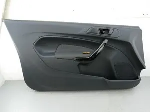
Door Trim :- Door panels serve as an interface between the interior of the car and the inner workings of the door, and between vehicle occupants and the door. They are expected to meet a variety of design specifications regarding safety, aesthetics, and functionality.
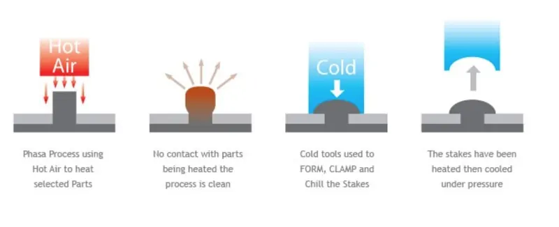
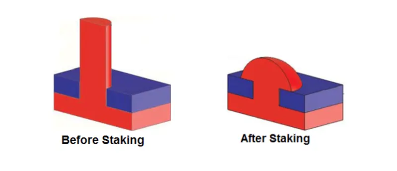
Heat staking :- Heat staking also known as thermoplastic staking is the process of joining two dissimilar materials together. In heat staking we use local heating and cooling to raise the temperature of plastic components and allow plastic reforming to be carried out. This reforming can be used in a wide variety of applications.
Heat staking can be performed using wide range of thermoplastic materials including polypropylene, ABS, polycarbonate and many others. The integrity of a thermal staked assembly depends greatly upon the geometric relationship between the boss and the thermal tip.
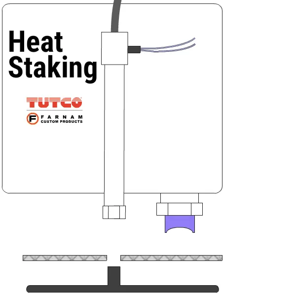
The heat staking tip is brought into contact with the thermoplastic part to be reformed. The heating tip is then heated by direct electrical heating within the tip for a short period of time. The heated tip softens the plastic material and forms the melted plastic into the shape of the tip.
In addition, heat staking has many benefits. However, this depends upon the application, benefits include :-
- Heat staking enables similar and dissimilar materials to be joined.
- Local heating ensures that there is no damage to adjacent materials.
- There are many heat stake shapes available through custom designed tools.
- No mechanical vibration.
- Very simple design guidelines are required for success.
Although proving extremely beneficial for many, heat staking has its drawbacks :-
- If formers are too cold, they will strain the stake causing stress, which may also impact breakages leading to failure.
- Temperature control is difficult to achieve with large multiple staking applications.
- The number of posts heat staked at one time is limited by the configuration design of the parts being assembled.
Design Methodology :-
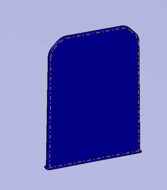
Class A Surface :- Class A SurfClass-A surface means visible surface. It gives the aesthetic of the component which is created by the styling team and gives to the part design engineer to create the part with all engineering aspects.
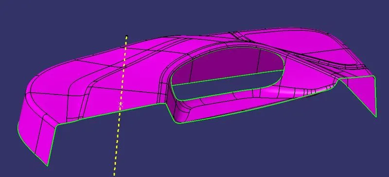
Check for continuity of the given surface using Join or Boundary commands.
If there are no gaps on the A surface, create tooling axis.
Draft analysis on Class A Surface :-
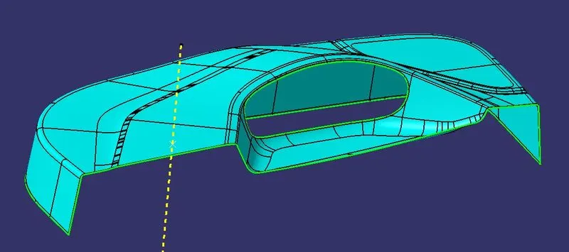
Class B Surface Creation :- Class B surface means thickness of a part it is not visible and is inside part. In other words, Class B surface is a surface below a certain thickness from the class-A surface. This is the surface that contains engineering aspects of a model.
- Create offset surface of Class A about 2.5mm inward direction.
- Check for the discontinuity and rework on the offset surface using extract, multi-extract, multi sections surface.
- Join the surfaces and ensure the final Class B surface created has no gaps.
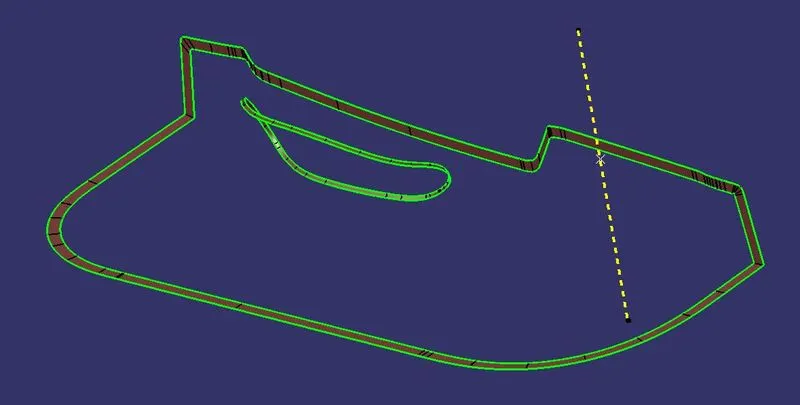
Class C Surface Creation :- Surface that joins class-A and class-B surfaces is class-C surface. Class C is often specified for interior surfaces not readily visible, surfaces that will be covered by another part when assembled.
- Create the sweep surfaces with reference to tooling axis, with refrence of surface and with the help of multi section surface the Class A boundary is created.
- Finally join all the sweep surfaces and ensure the continuity of the Class C surface.
Creating the Final surface
- For creating the Finals door trim surface, join the Class A and Class C surface together.
- Then Extrapolate the B surface little bit outward direction to make sure that there would not be any gap when trimming with joined surface.
- Then trim the extrapolate Class B surface with Join surface (Class A and Class C)
- Ensure the final surface has no gaps using the boundary command.
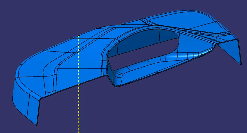
- Make a solid part body using the close surface command in the part design workbench
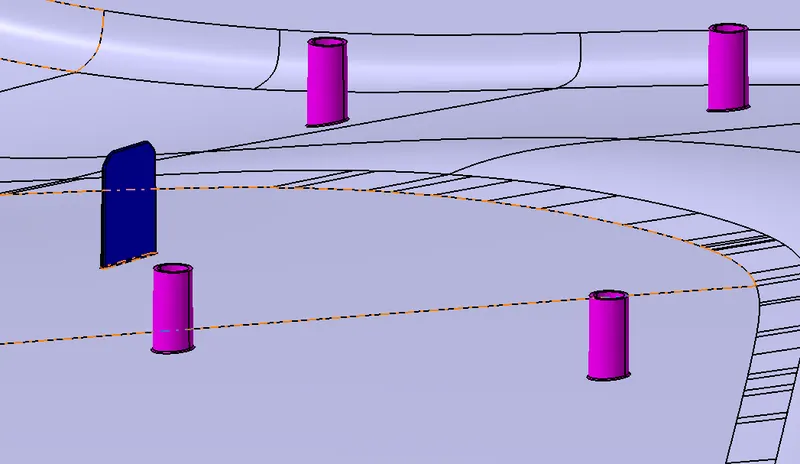
Locators :- Locating pins are the structures which are used to position the child part with parent part while assembling. These locators were placed in the multiple location on the part depending upon the degrees of freedoms which needs to be arrested. They were classified as two-way locators and four-way locators.
4 Way Locators :-
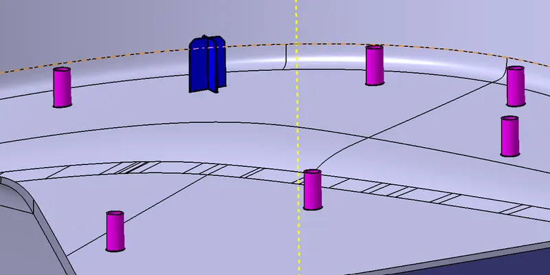

2 Way Locators :-
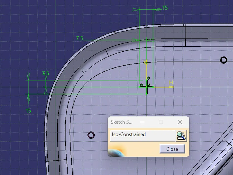
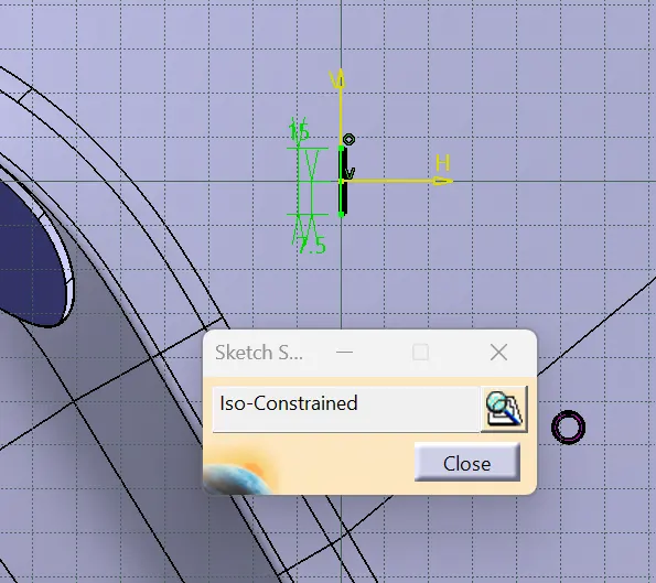
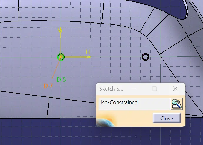
Iso Constrained Sketches :-
For 4 Way Locator :-
For 2 Way Locator :-
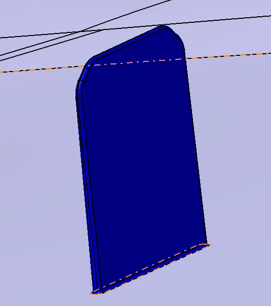
For Heat Stakes :-
Design procedure :-
- Create positioned sketch and make required iso-constrained sketch.
- Pad the sketch profile with reference to the tooling axis. Locator’s height should be more than that of heat stakes.
- Create chamfer of 2*45 degree on the to face for the easy entry of the locators to the holes.
- Draft angle 0.5 degree is given to all the faces.
- 0.25 mm edge fillets are given to all the edges.
- Finally, using union trim Boolean operation, trim the locators with the door trim body part.
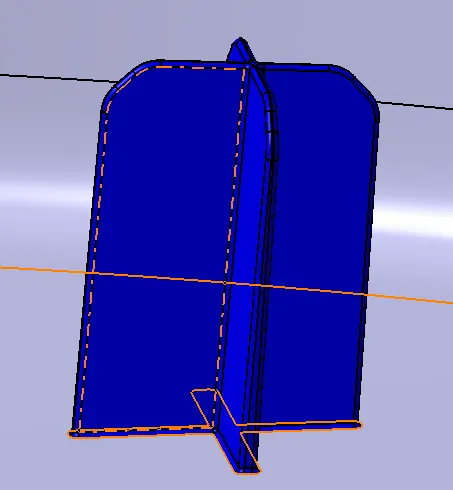
Heat stakes creation :- Heat staking method is commonly used in OEM to assemble door trims, instrument panels etc. The below image shows a simple animation of heat staking process.
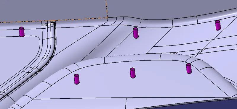
Heat stake Design procedure :-
- Using positioned sketch, create sketch of the heat stake profile.
- Pad it with reference to the tooling axis.
- Heat stake height should be lesser than the height of locators provided.
- Thickness should be 40% of the component main thickness to avoid sink marks on the A surface.
- Provide draft angle of 0.5 degrees on both inside and outside walls of the heat stake.
- There should be minimum 50 mm gaps between each heat stakes.
- Create more heat stakes by special copying option and translate it to desired points.
- Then union trim them with door trim part body to get the final component.
Draft Analysis On Final Part :-
3D Part model in various orientations (Isometric, Front, Side, and Top View) :-
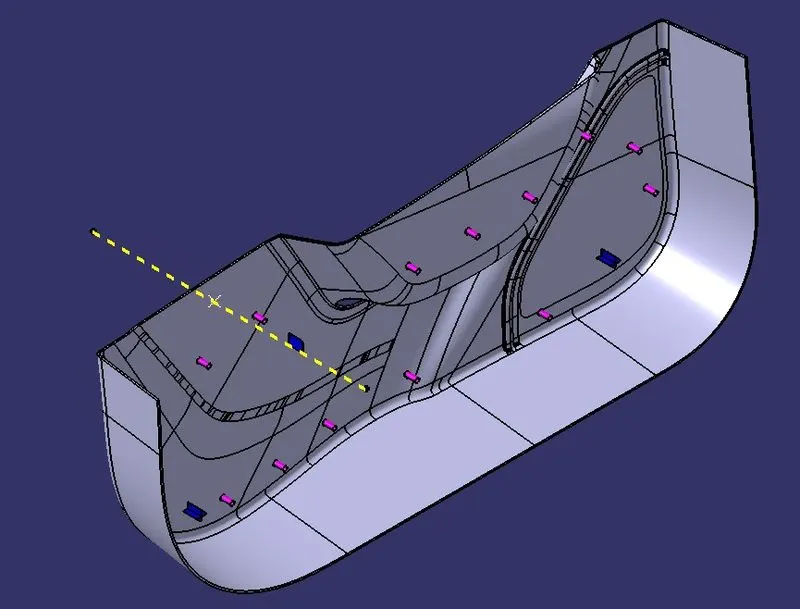
Isometric View :-
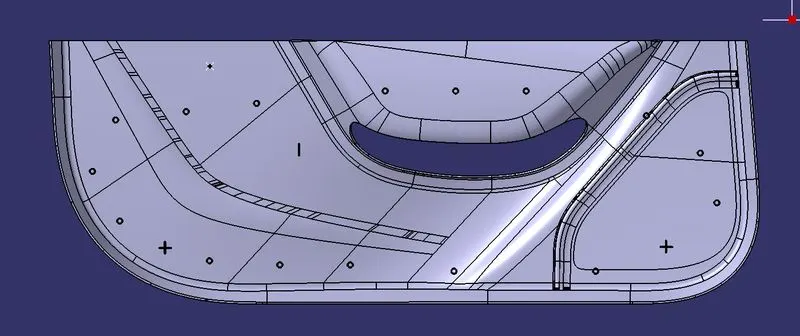
Front View :-
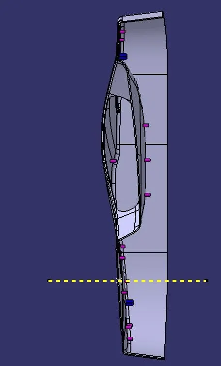
Top View :-
Side View :-
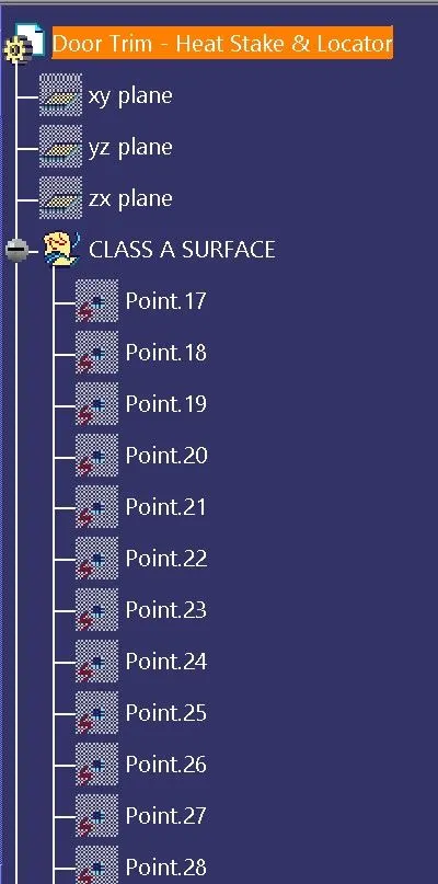
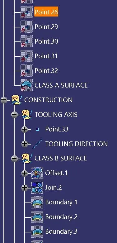
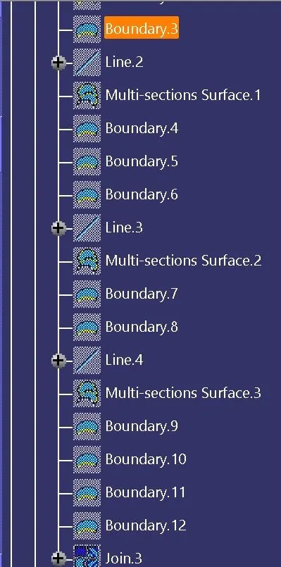
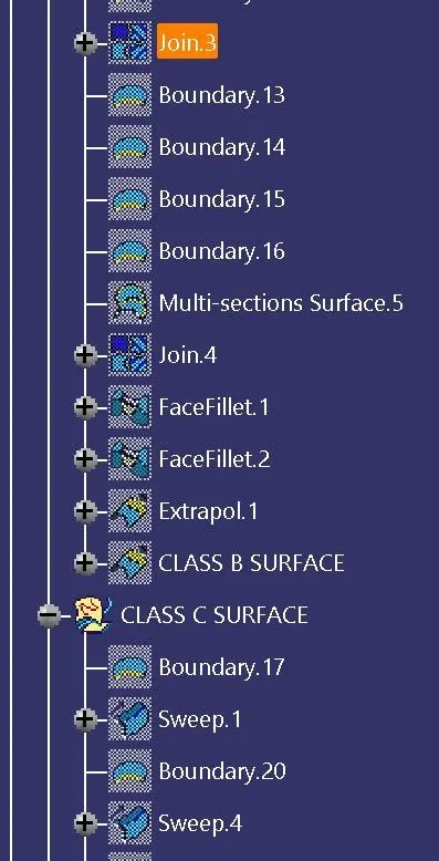
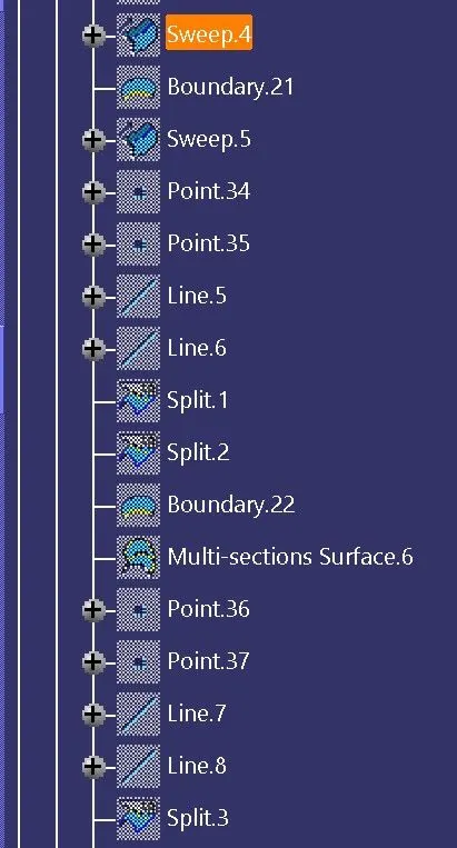
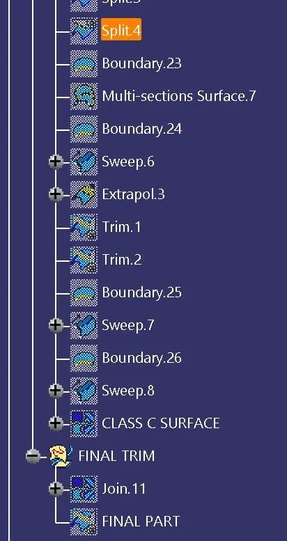
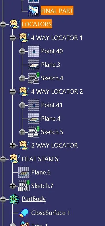
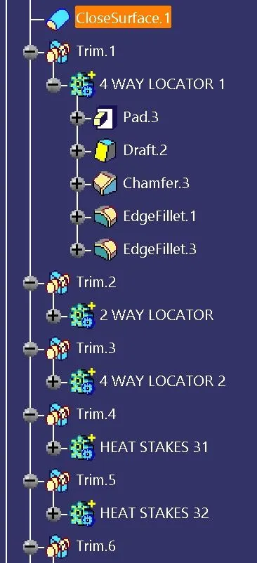
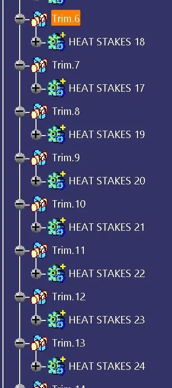
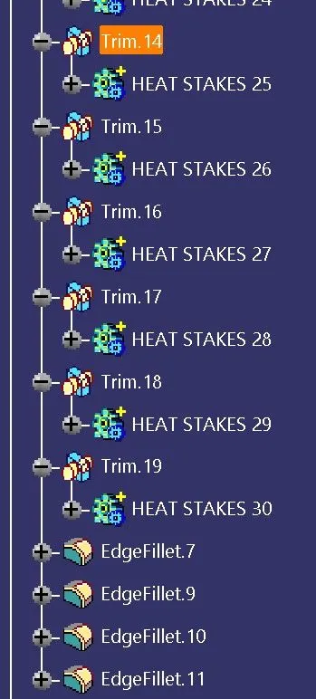
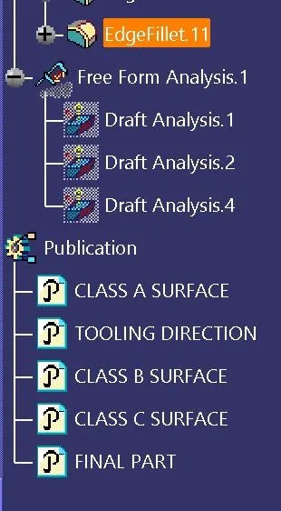
Tree Structure :-