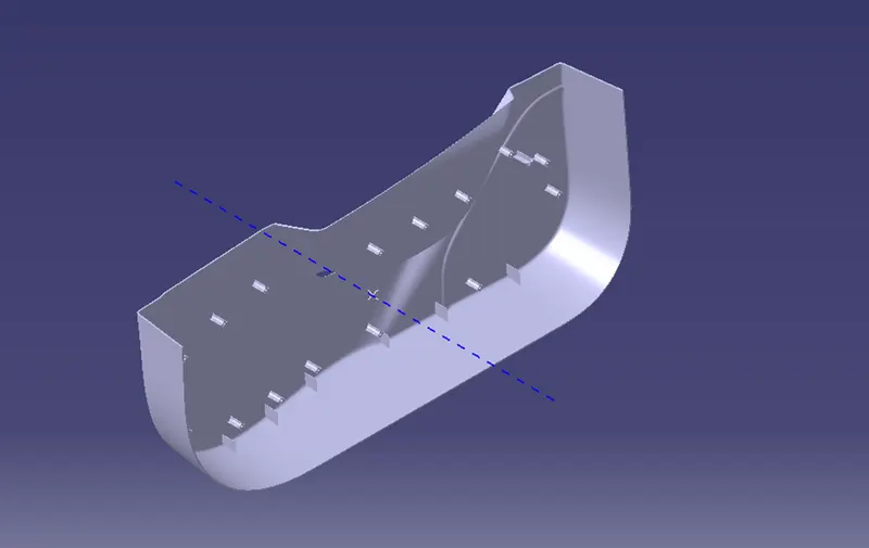
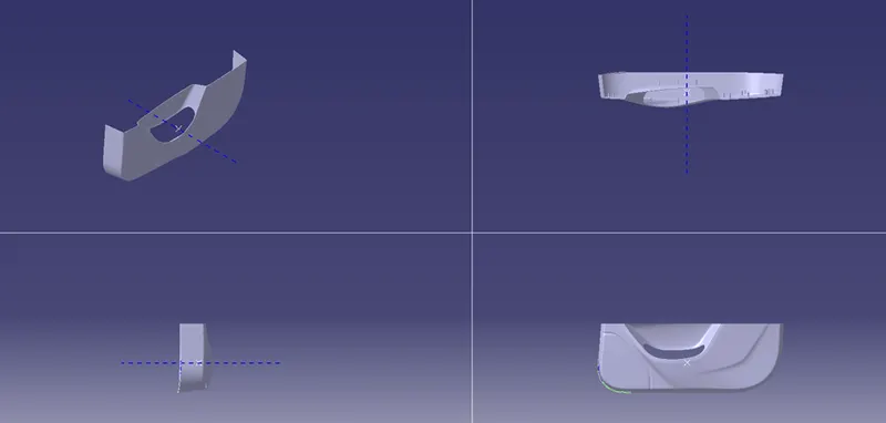
Week 10 - Challenge 3 - Door Trim Lower with Engineering Features
The primary goal of this task is to use CATIA V5's "Generative Shape Design" workbench to develop a solid body for a "Door Trim Lower" utilising the closed surface approach. 'Draft Analysis' is carried out on the body of the solid door trim.
Overview:
Initially, we need to offset the given Door Trim class A surface in the inner direction to the required thickness (here the thickness is 2.5mm). After that, we need to close the patches on the offset surface of the bumper, the patches are formed due to the fillets on the Class A surface. Once all the patches are closed properly join them together to make a proper class B surface and now sweep the boundary of the class A surface to trim with the class B surface to make a closed body. By using the closed body command in the Prat workbench we can get the solid body from the closed surface of the Door Trim., I performed a draft analysis for it to check whether all the surfaces are drafted properly or not (The draft angle for the plastic component is 0.5deg to 3deg)
Tooling axis:
I took a surface from class A, used the point command to make a point in the centre of the surface, and then generated a line passing across the x-axis at that point to establish the tooling axis. I then carried out a draught analysis check along that line to determine whether the tooling axis that was established was in the proper location. If the tooling axis is in the proper location and direction on both sides of the area shown with green in the draught, analyse the surface.
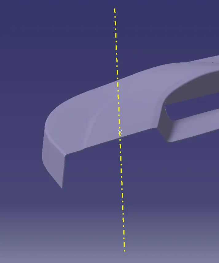
Class a :
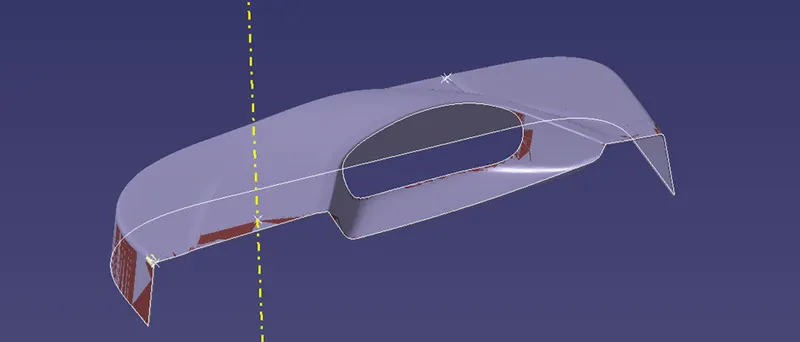
Class b:
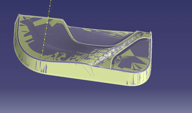
Class c:
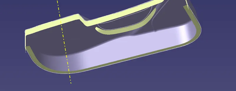
It is used to join
A+c:
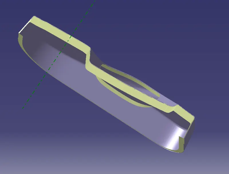
Drafting analysis:
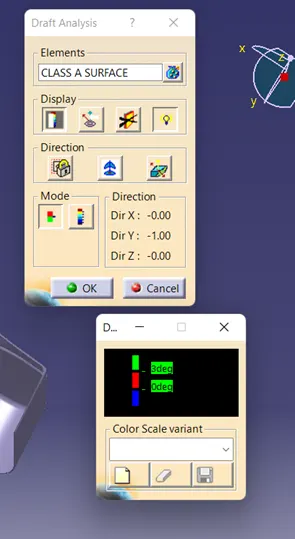
Before we produce solid and create B-side features, we run the draught analysis check for class A surfaces. I then set the compass to the tooling axis
Tooling axis:
The direction in which the mould, core, or hollow opens and closes is known as the tooling axis. The tooling axis must be established before creating a component.
Procedure
Verify that the Class A Surface is connected, meaning there are no gaps between the surfaces.
Determine the appropriate tooling direction by analysing the component in the x, y, and z directions (here Y).
By removing it, you may turn a flat surface into a point.
The tooling axis is determined by drawing a line across the point that is parallel to the flat surface that was removed.
Given surface
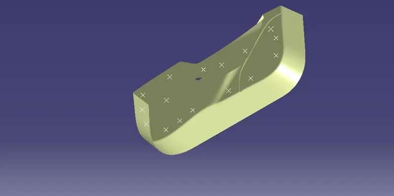
Tooling Axis Through Bisecting
Verify that the Class A Surface is connected, meaning there are no gaps between the surfaces.
Determine the appropriate tooling direction by analysing the component in the x, y, and z directions
By removing it, make a point at the base surface.
Use that position as the starting point for an axis system.
Make a point where class A and the x-axis cross.
Create two lines using examples of faces that you believe will cause issues.
With the lines drawn, make a bisecting line that will give us the tooling axis.
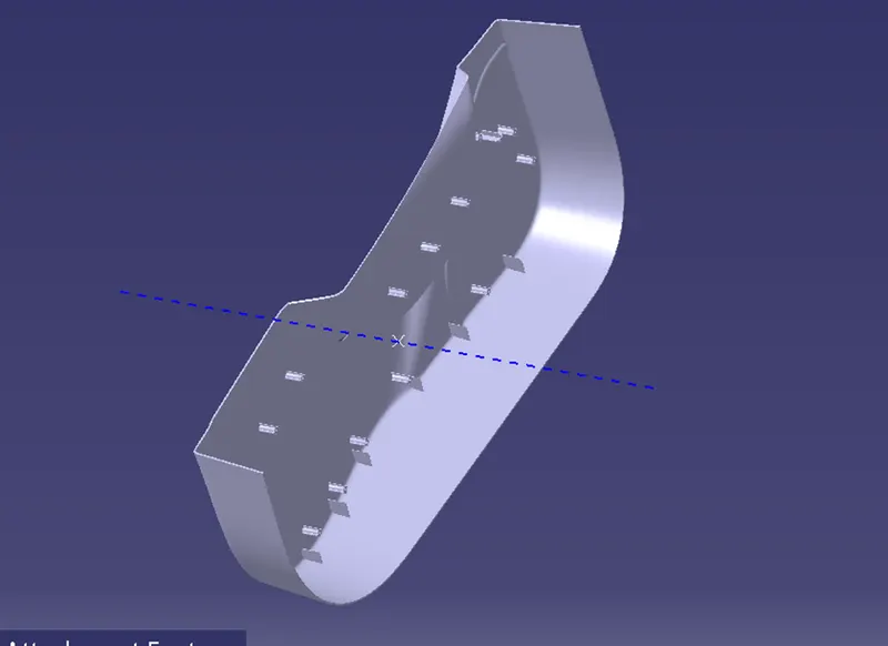
To clear the draught direction in this instance, we will introduce a tooling axis from the side that is prependicular to the face that is not clearing the draught in the main tooling axis direction when making the heat stakes
First change the view to " Customize View Parameters" and select Material option.
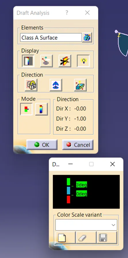
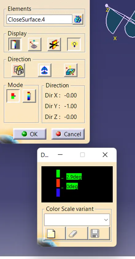
Select Feature Draft Analysis from the tool bar.
Click on the direction, drag and drop the compass to the component such that it should coincide with the tooling axis.
Lock the draft direction and click on the component.
Green colour shows the positive draft, cyan as zero degree and red as negative drafting
Class a:
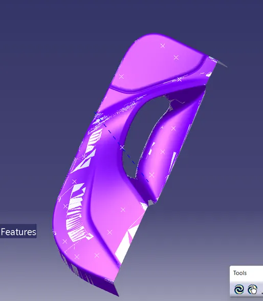
Class A surface is any of a set of freeform surfaces of high efficiency and quality. In other words, Class A surface is the aesthetic surface.
Class c:
It is used to join class a & class c
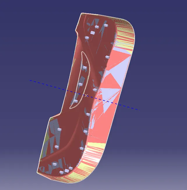
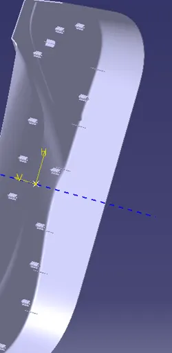
Heat stakes:
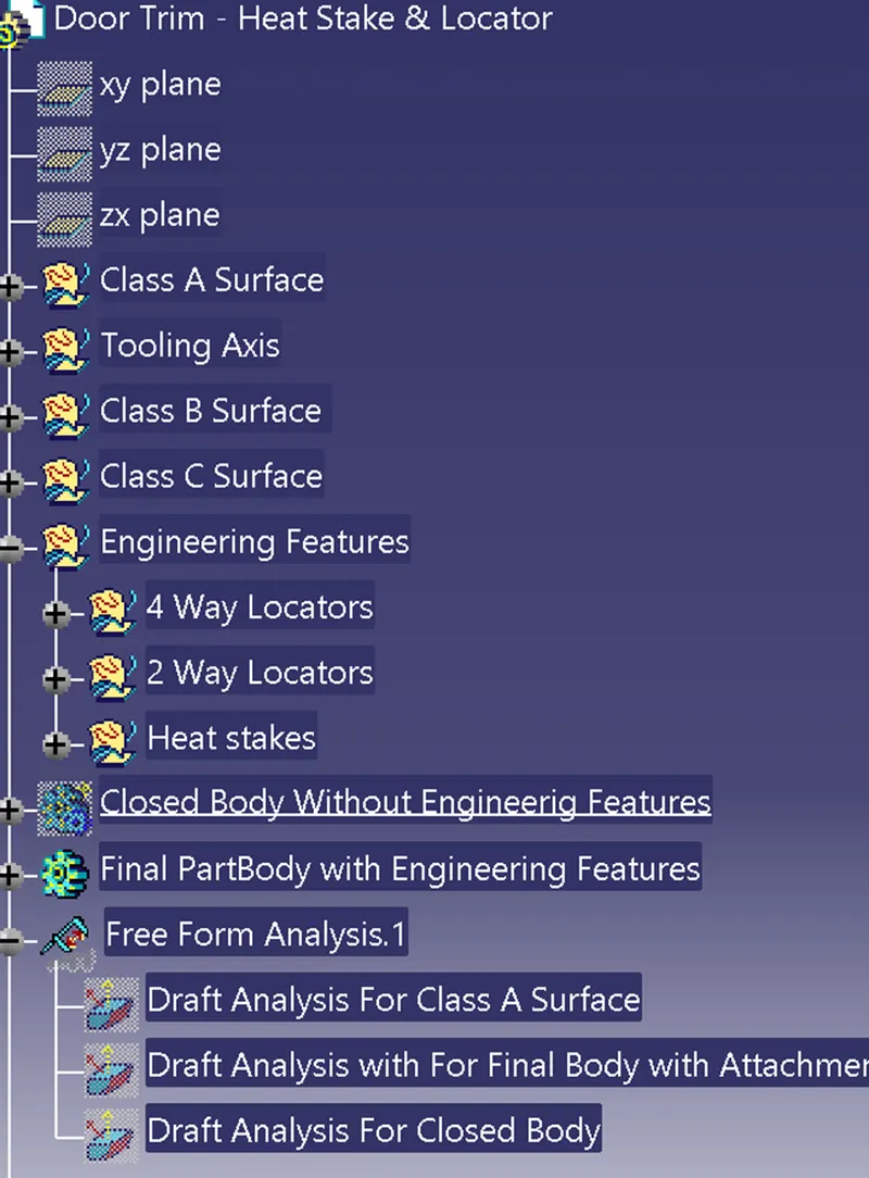
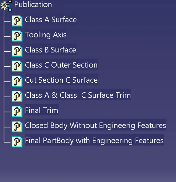
Tree structure:
Drafting analysis:
Isometric view: