Week 10 - Challenge 3 - Door Trim Lower with Engineering Features
Door Trim Lower with Engineering Features
Create the Door Trim Lower Plastic component through the given Class-A surface. To begin with, the tooling axis for the given Class-A Surface should be created meeting the requirements of the draft angle and at the end perform the Draft analysis on the model.
Create the Heat Stakes and the locators considering the design rules mentioned in the video for the door applique.
Heat Stakes design-
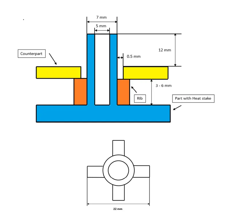
- Counter Part Thickness - Will be given as input
- Component Wall Thickness - Will be given as input
- Length of the Rib - 20 mm
- Height of the Ribs - 10 mm
- Inner Diameter of Heat Stake (d) - 5 mm
- Minimum clearance between heat stake and counterpart - 0.5 mm
- Height of the Heat stake - Depends on the rib height and counter-part thickness
- Minimum fillet of Heat Stakes - 0.25 mm
- Minimum Draft Angle of Heat Stakes - 0.5 degrees
Given Class A Surface-
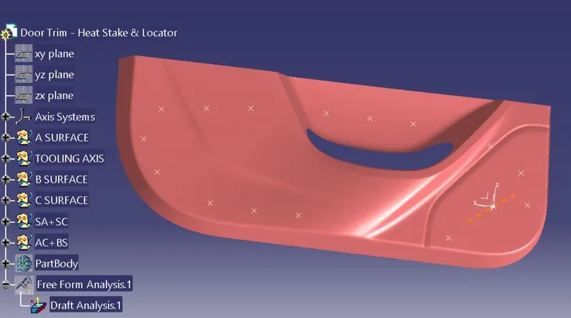
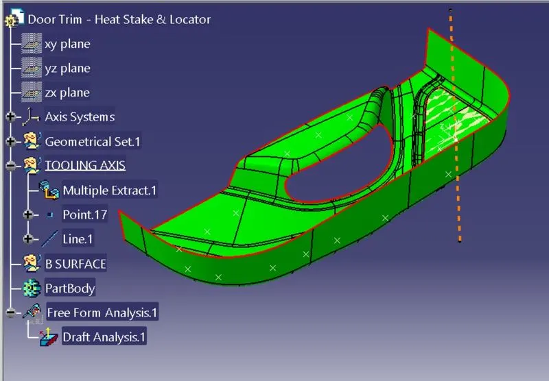
TOOLING AXIS:
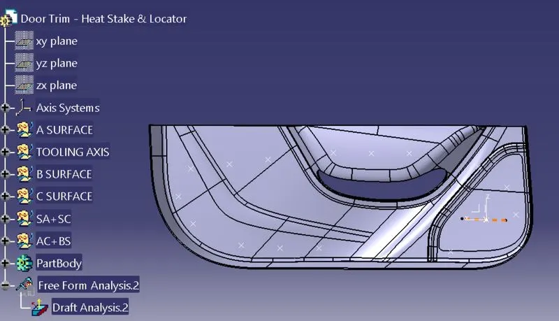
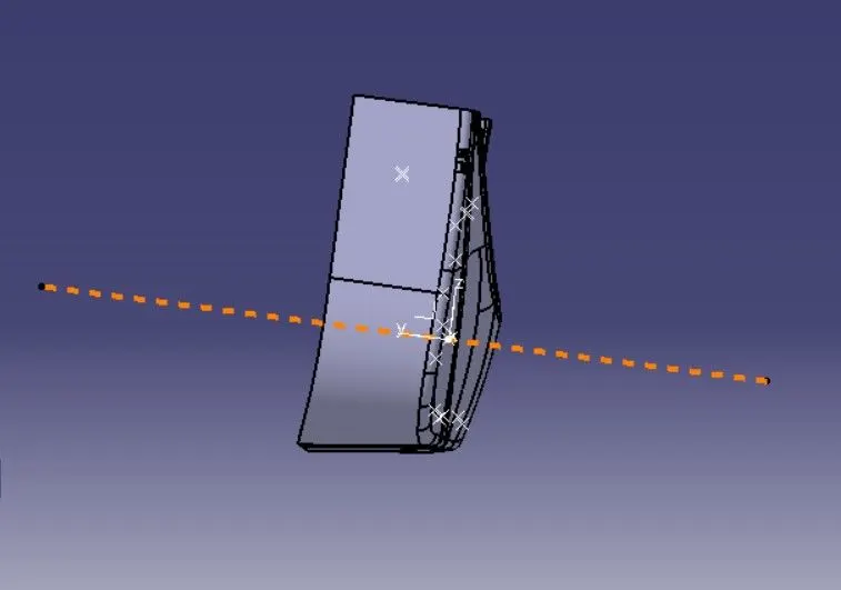
To create the tooling axis, I extracted a surface from class A and created a point in the middle of the surface by using the point command and created a line at that point through the x-axis. Now, I performed a draft analysis check from that line whether the created tooling axis is in the correct position or not. If in the draft, analysis check the surface highlighted with green colour on both sides of the surface the tooling axis is in the correct position and direction.
Class B Surface-
To create class B surface offset the class A with proper direction and distance. Here distance is the thickness of the component. As no given thickness is provided, so we are asuming the thickness value is 3MM. Reasult after offseting-
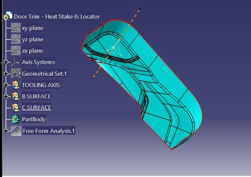
Class C Surface-
To create class C surface create boundary using class A surface boundary with 'Boundary' command in 5 parts. And use 'Sweep' command to create a surface that is in 90 deg. angle with class A surface. The reasulyent surface will be the class C surface.
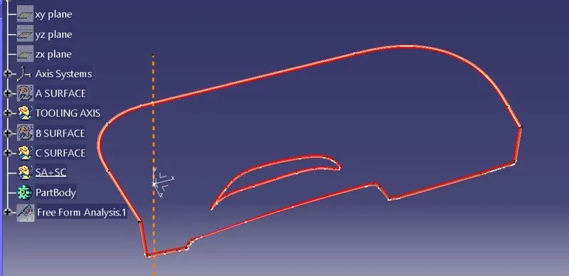
SURFACE A+C-
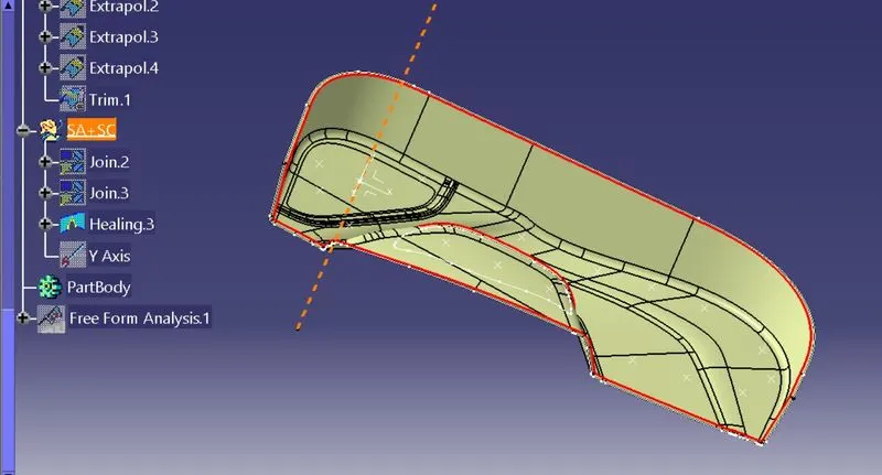
Final Closed Surface-
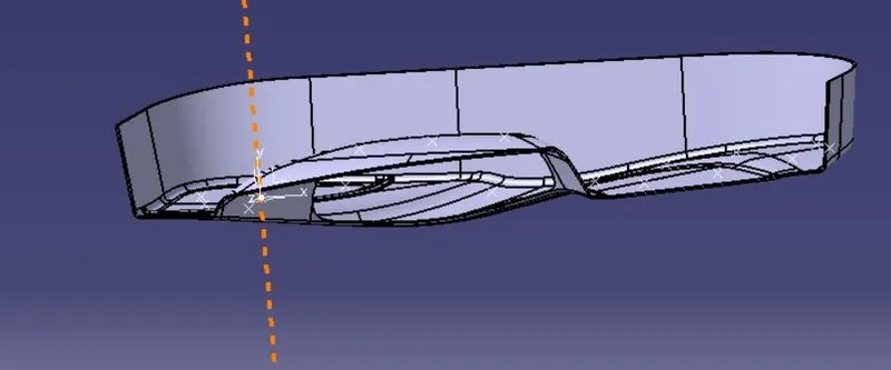
Class C surface trimmed with class B surface properly and joined with class A.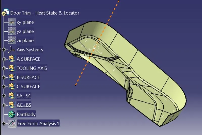
Solid Body-
Using 'Closed Surface' command of Part Workbench we have to make make the body solid.
CREATION OF LOCATORS:
To create the locators, I created a sketch on the body. After creating the sketch, I pad it 20mm in height and thicken it to 1.3mm and I drafted it with 0.5deg in the direction of the tooling axis. I gave 5mm of chamfer with 45deg of inclination and after I gave a fillet of 0.25mm radius.
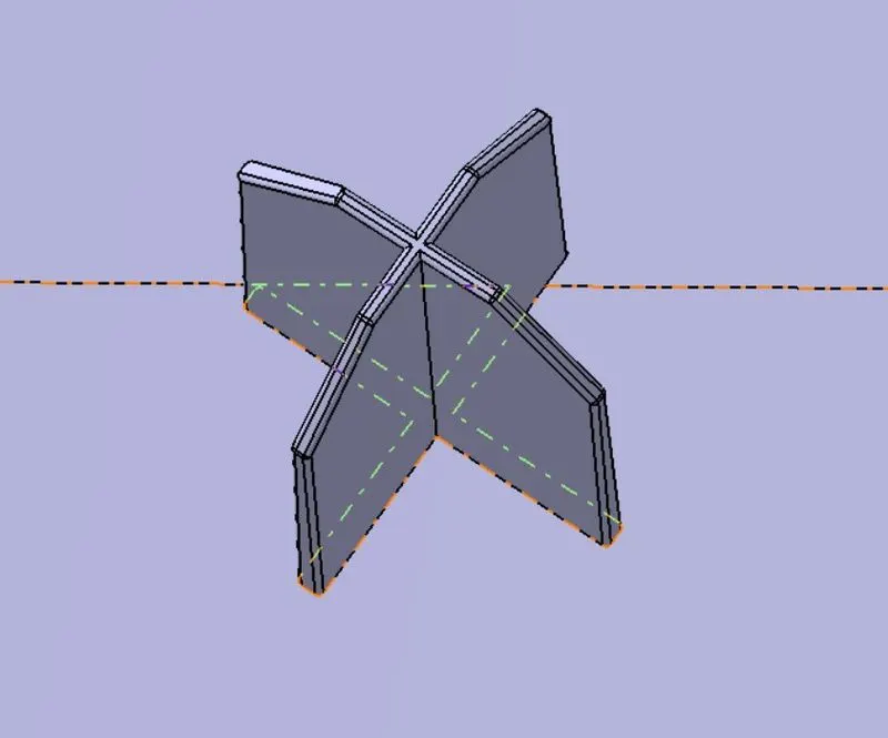
Create Heat stake.
Draw a sketch on the surface. After the creation of the sketch, Pad it to 18mm height and a draft angle of 0.5deg on both sides (inside and outside) and then provide a fillet with a 0.20mm radius. After creating the heat stake, create the ribs for supporting purposes. To create the ribs, draw a sketch and padded it to height less than that of the heat stake and 1mm in thickness. After padding the ribs, drafted 0.5deg in the tooling axis direction and fillet it with a 0.20mm radius. Finally, use union trim on the ribs with a heat stake to remove the ribs as per the requirement, which are present inside the heat stakes.
Copy and translate the heat stake to all the positions as needed.
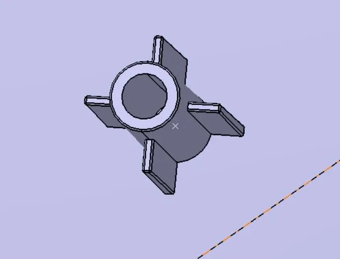
Create ribs as shown below.
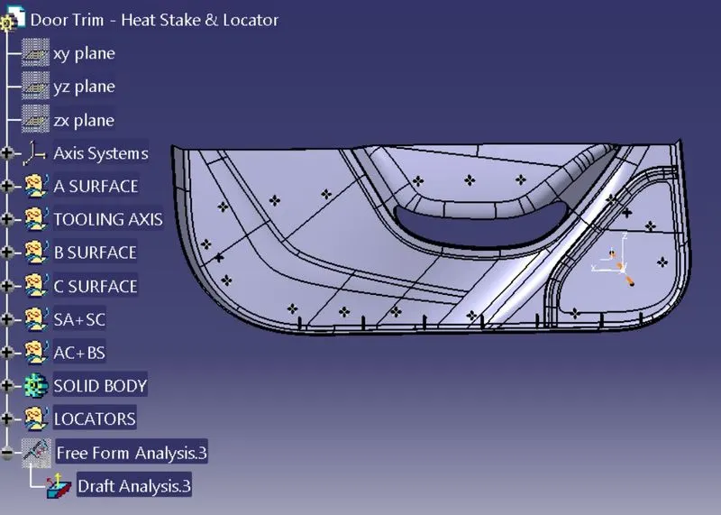
draft analysis of final product:
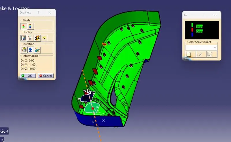
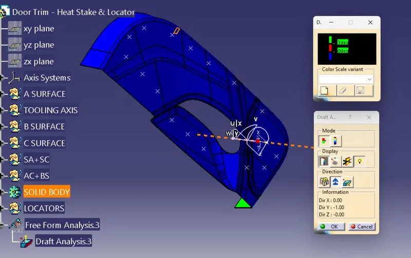
CONCLUSION:
the Door Trim Lower Plastic component through the given Class-A surface. To begin with, the tooling axis for the given Class-A Surface has created meeting the requirements of the draft angle and at the end perform the Draft analysis on the model.
the Heat Stakes and the locators considering the design rules mentioned in the video for the door applique was created.