Week 10 - Challenge 3 - Door Trim Lower with Engineering Features
1. OBJECTIVE:
Create the Door Trim Lower Plastic component through the given Class-A surface. To begin with, the tooling axis for the given Class-A Surface should be created meeting the requirements of the draft angle and at the end perform the Draft analysis on the model.
Create the Heat Stakes and the locators considering the design rules mentioned in the video for the door applique.
2. Definitions
Class-A Surface:
Class A surface is made from scanned data with different software like allias etc.. lass A surface having CURVATURE CONTINUITY
Class-B Surface:
Class-B surface having all features(Rib,boss,snap etc). It is created by extracting the all wall of the Class-A surface.
Class-C Surface:
Class-C Surface is used to joining the Class-A Surface & Class-B Surface. This surface is generated by sweeping the Class-A surface boundary.
Draft Analysis
The Draft Analysis allows the user to easily analyze a part for proper draft angle. A Draft Angle describes the amount of taper for molded or cast parts perpendicular to the parting line
Tooling axis
Tooling axis is tells about the in which direction core should be move. This tooling axis creating by Point and Direction .
Heat Stakes
Heat Staking is a pulsed-heat process to join two or more parts out of which one at least is made of plastic. The process is to deform the plastic material using heat and force at a set process time. The bond is made by partially deforming the plastic part in order to fix the other.
Locators
Locators are used to restricts the motion along 1 or 2 axes. They are generally types, those are 2 way locators, 4 why locators
Dog house
Dog is feature which helps to avoid sink marks. Dog houses are used as supporting feature. Sometimes other engineering features like snaps; locators etc. are mounded on them to increase their strength.
3. Procedure
3.1 Tooling axis making
- Created a point on surface.
- Created line from point with Y-direction. And named as tooling axis.
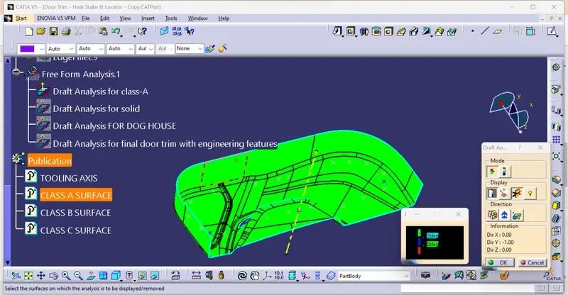
3.2 Draft analysis for Class-A Surface.
- Insert--->Analysis--->Feature Draft Analysis
- Draft analysis window will appeared. In that using the compass and define the new current draft direction.
- Locked the draft direction.
- And then click on the surface.
- Color coded on the surface with reference to the draft angle.
Green for 3.0°,
Blue For 0°
Red for Below 0°
3.3 Creating Class-B Surface
- Offset the class-A surface with 2.5mm
- Fill the patches with multi-section surface and then join them.
- Extrapolatethe inner and outer surfaces and named as Class-B surface.
3.4 Creating Class-C surface
- Taking boundary from class-A surface
- Sweep the boundary with draft direction as tooling axis and draft angle 90°
3.5 Joining the Class-A, B & C surfaces
- Trim the Class-C surface with Class-B surface, and named as Class-B+C
- Join the Class-A surface and Class-B+C
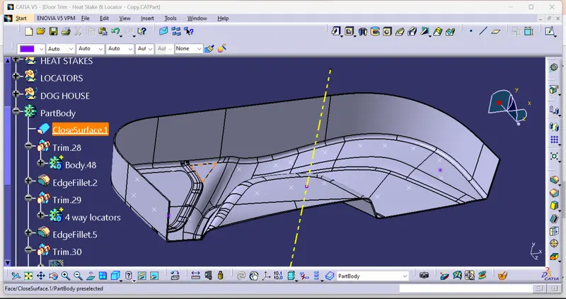
3.6 Solid model creation.
- Joined surfaces converted in solid model by Close surface command
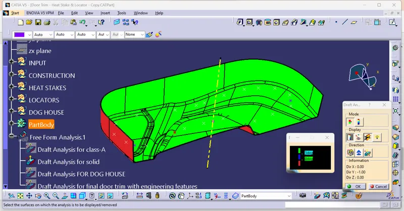
3.7 Draft analysis for solid model.
- Insert--->Analysis--->Feature Draft Analysis
- Draft analysis window will appeared. In that using the compass and define the new current draft direction.
- Locked the draft direction.
- And then click on the surface.
- Color coded on the surface with reference to the draft angle.
Green for 3°,
Blue For 0°
Red for Below 0°
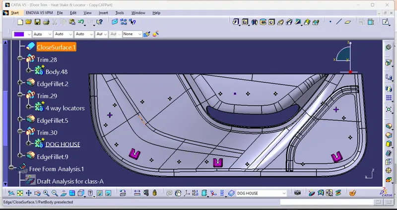
3.8 Heat stake, locators & Dog House creation
- Heat stake, locatorsDog house created as per design rule
3.9 Creating side core tooling axis
- Created a line with X-Direction and name as side core tooling axis.
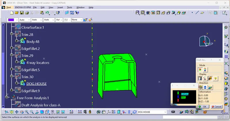
3.10 Draft analysis for final door trim with Dog House
- insert--->Analysis--->Feature Draft Analysis
- Draft analysis window will appeared. In that using the compass and define the new current draft direction.
- Locked the draft direction.
- And then click on the surface.
- Color coded on the surface with reference to the draft angle.
Green for 0.45°,
Blue For 0°
Red for Below 0°
4. Result
Initially Tooling axis was created by point and direction method. And the draft analysis is applied for class-A surface. After that Created the Door trim component through the given Class-A surface with 2.5mm thickness. Now draft analysis is applied for plastic component of Door trim. After that dog houses are created along with side core tooling direction, and draft analysis applied.