Week 10 - Challenge 2- Attachment Feature Creation (Dog House)
INTRODUCTION:
DOG HOUSE:
Dog house is an engineering feature used in plastic design. Dog houses are used as support feature. Sometimes other engineering features like snaps, locators, and screw bosses are mounted on them to increase their strength.
Dog houses are subjected to draft analysis to prevent breakage of the component during ejection from the mould cavity. Dog house and other engineering components are built on the B-surface.
TOOLING AXIS CREATION:
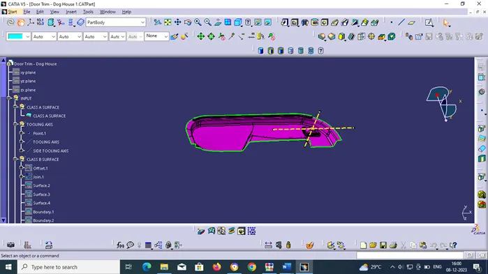
In injection moulding, the Class A surface is first analysed to determine the axis or tooling direction that separates the Moulds. Tooling direction is critical for plastic product design because it determines Mould direction
DRAFT ANALYSIS:
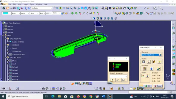
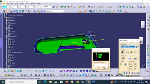
For moulded or cast parts, the draft angle is the amount of taper perpendicular to the parting line. It is measurable in degrees. Because plastic shrinks and sticks on moulding surfaces as it cools, we draft the walls of the plastic part so that it ejects or breaks free from the moulding surfaces more easily and without dragging. To reduce the risk of damage to the parts and ensure ejection, a functional injection moulding part must have drafts on both the cavity and core sides.
NOMINAL VALUES FOR DRAFT ANGLES:
· 3 Degrees is a nominal draft angle
· 5 Degrees can also be manufactured. Increasing the manufacturing cost
· 7 Degrees is considered for Textured surface parts
IMPORTANCE OF DRAFT IN INJECTION MOULDING:
· Reduces the possibility of part damage due to friction during the release
· Reduces Mould wear and tear
· Ensures a uniform, smooth, unscratched finish
· Ensures the integrity and uniformity of other surface finishes and textures
· Reduces overall cooling time by reducing or eliminating the need for unusual ejection setups
STEPS FOLLOWED FOR DRAFT ANALYSIS:
· The created part must be changed to the material mode in the display frame
· Compass is enabled and placed in the direction of the Tooling Axis
· The lock command is then used to fix the compass along the tooling axis
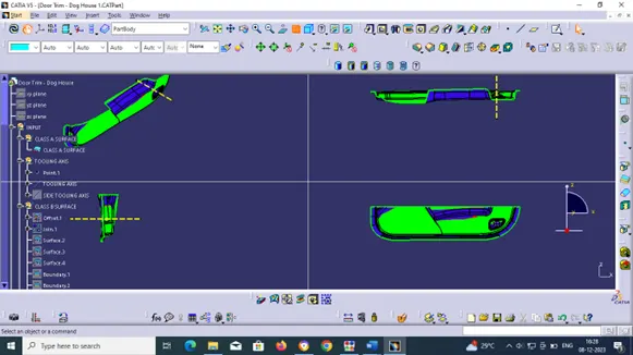
· Colour codes are classified and a Draft angle is applied
· Running point analysis is used to display permissible draft angle
GIVEN INPUT:
CLASS A SURFACE:
Class-A surface means visible surface. It gives the aesthetic of the component which is created by the styling team and gives to the part design engineer to create the part with all engineering aspects.
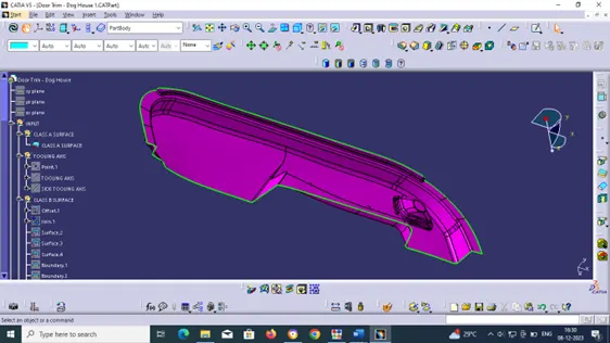
Check for continuity of the given surface using Join or Boundary commands.
If there are no gaps on the A surface, create tooling axis.
PROCEDURE FOR CREATING TOOLING AXIS:
· Check the best possible tooling direction by manually adjusting the compass.
· By analysing it is found that the y axis as tooling direction would clear most of the faces without any difficulties.
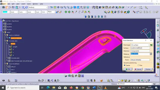
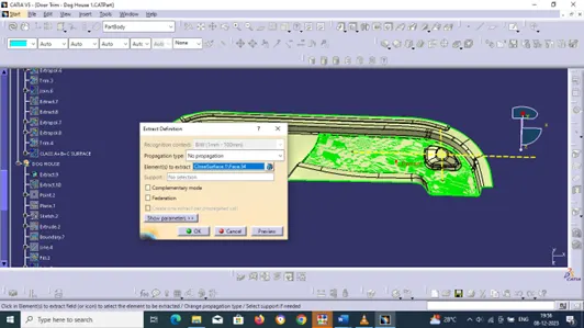
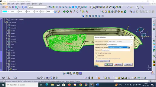
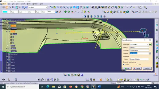
· Now extract any surface and create a mid-point on it.
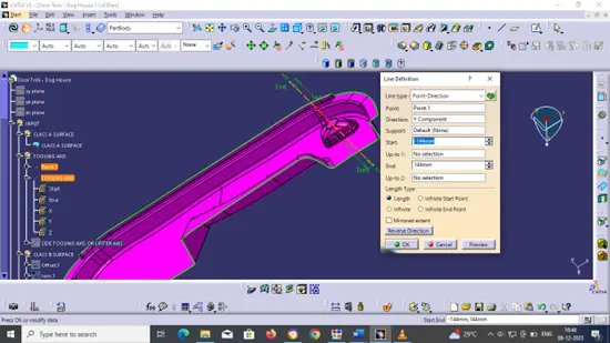
· Then create a dummy axis creating a line on the point and direction along the y-axis.
· Perform draft analysis to find whether the given axis clears the draft analysis. If not create a new tooling axis.
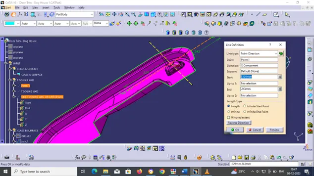
· Also creating side tooling axis or lifter axis for better view for uncover surface.
Point 1:
Tooling axis:
Side tooling axis:
CLASS-B surface creation
Class-B surface means the thickness of a part it is not visible and is inside part. In other words, the Class-B surface is a surface below a certain thickness from the class-A surface. This is the surface that contains engineering aspects of a model.
Create offset surface of in CLASS-A about 2.5mm inward direction.
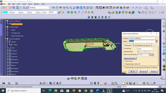
Check for discontinuity and rework on the offset surface using join, boundary, blend and join.
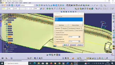
By join tool remove the surface which have gap on offset surface and form an individual surface.
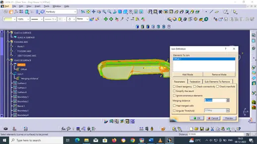
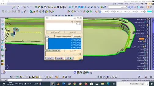
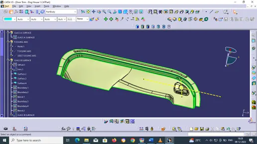
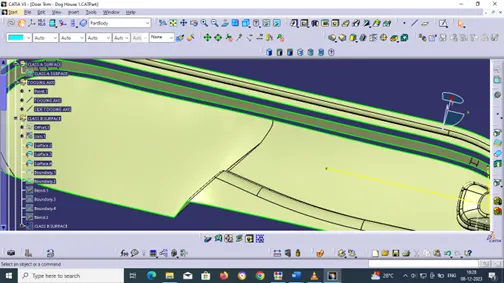
With the help of boundary definition boundary each surface extracted by join definition.
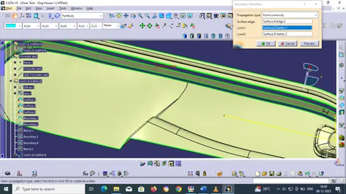
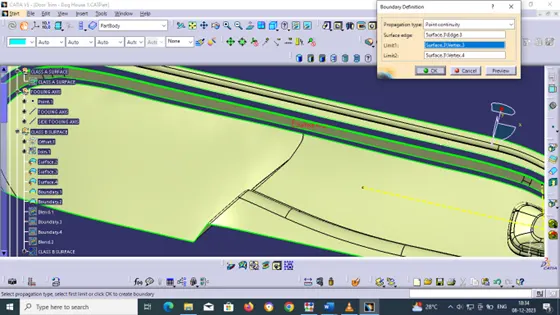
With the help of blend definition blend the two-boundary curve with their respective supporting surface.
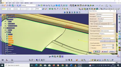
Similarly blend for another two boundaries.
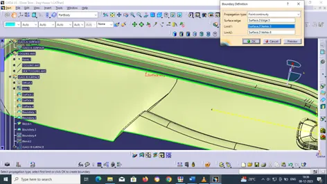
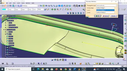
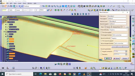
Join the surfaces and ensure the final CLASS-B surface created has no gaps.
CLASS C SURFACE CREATION:
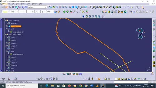
The surface that joins class-A and class-B surfaces is class-C surface. Class C is often specified for interior surfaces not readily visible, surfaces that will be covered by another part when assembled
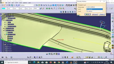
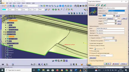
Create the boundary of Class A surface and then sweep with reference surface of guide curve of boundary created on class A surface with a reference of class A surface at 90 deg angle with a length of 2.5 mm
CLASS (A+B+C) SURFACE:
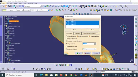
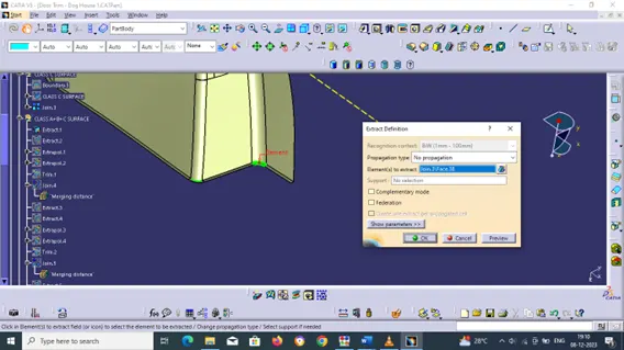
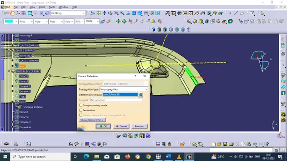
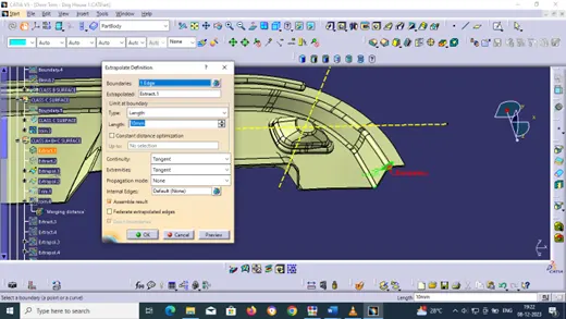
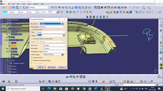
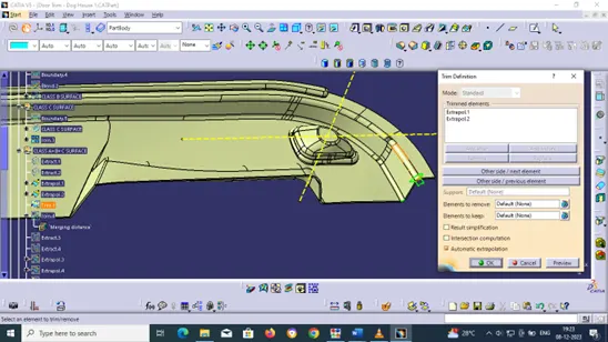
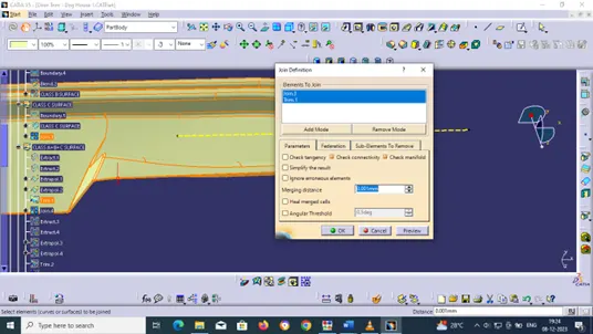
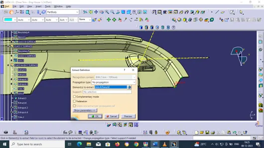
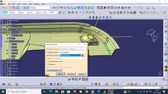
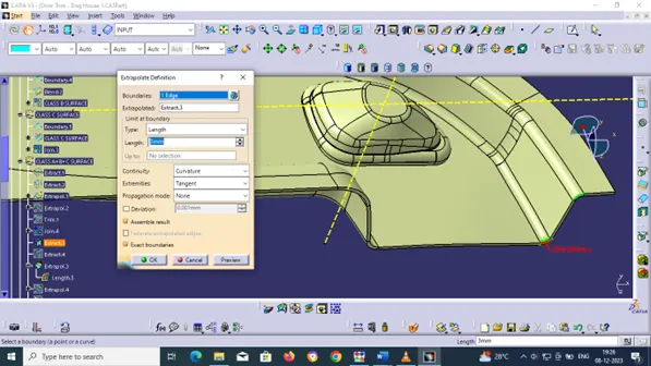
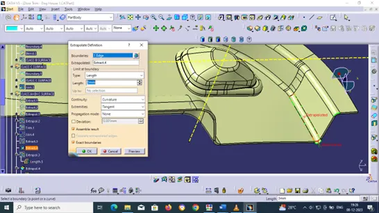
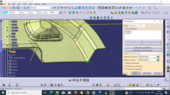
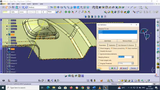
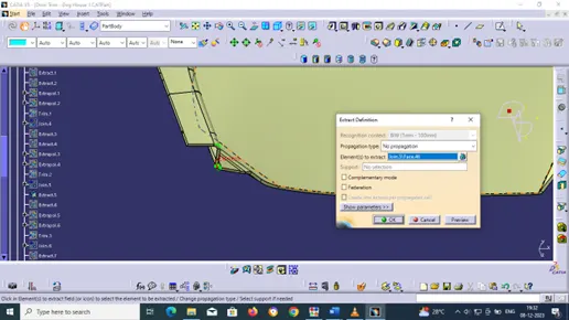
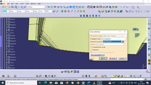
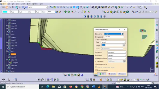
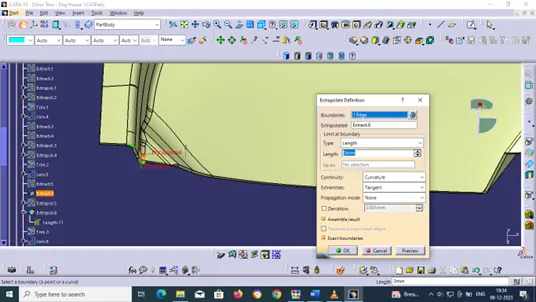
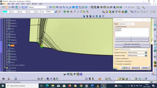
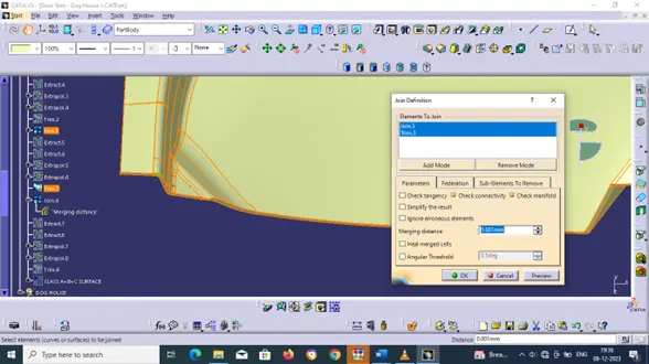
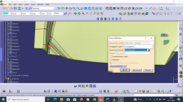
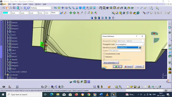
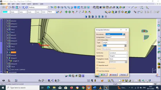
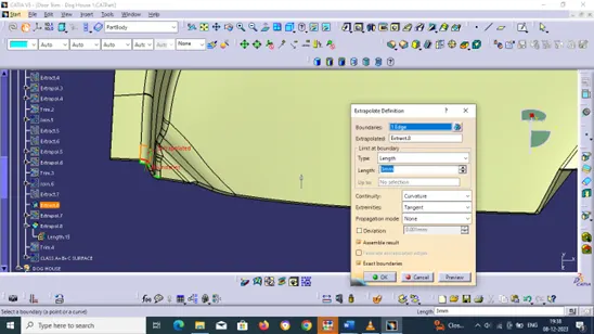
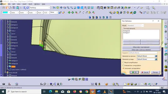
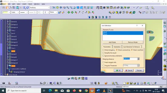
Here we combine all the surfaces into one closed surface using the Join command if any gap occur its shows in green colour now in order to fix those gap use Extract, Extrapolate, Trim and Join tool Command
CONVERSION OF CLOSED SURFACE INTO SOLID PART:
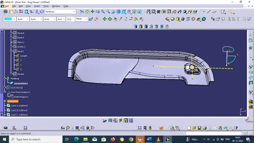
Using Close Surface Command in the part design workbench we convert the closed surface to a solid surface in the Part model
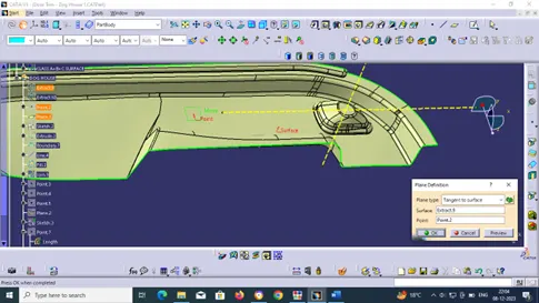
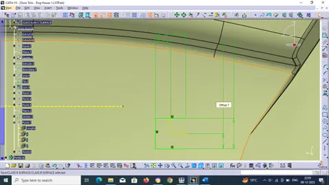
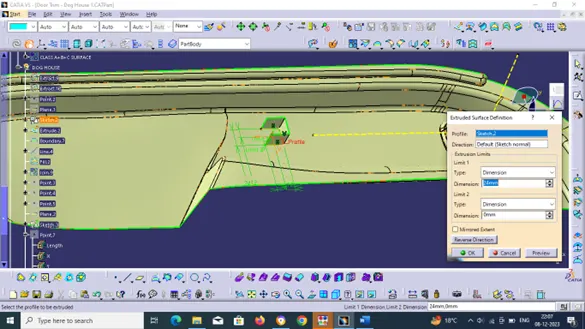
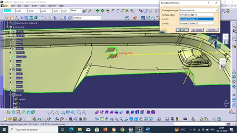
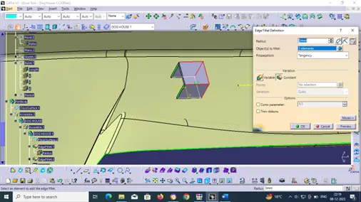
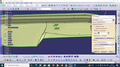
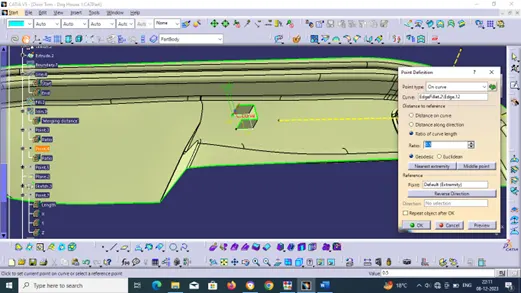
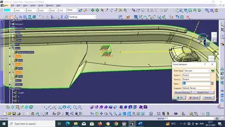
CREATING DOG HOUSE ON B SURFACE:
Dog houses are designed to avoid Sink marks created on the CLASS-A surface by screw bosses and to solve the length issues when giving screw bosses which need to be assembled to other components. It is also useful when perpendicular screw bosses are required on the part of the tooling direction.
The dog house is an engineering feature used in the plastic trim design. Dog houses are used as supporting features. Sometimes other engineering features like snaps, locators, etc. are mounded on them to increase their strength. Dog house and other engineering Features are built on B-surface.
DESIGN RULES FOR DOG HOUSE CREATION:
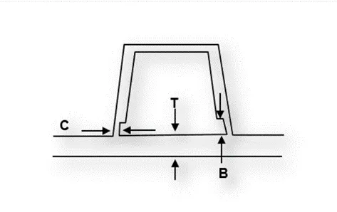
"C" is where the doghouse contacts the backside of the surface
Doghouse wall thickness at the intersection of the part wall (C) should be 40% or less than the main wall stock (T).
The height of (B) should be between 3.0 – 6.0 mm
C 40 % of T or ≤ T
B 3 - 6 mm
Width ≥12 mm
Width to Height Ratio 3:1
Draft 1.5
SIDE CORE AXIS OR LIFTER AXIS:
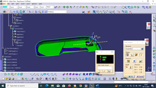
The side core axis is also a type of Tooling Axis, we can say it is an additional tooling axis for sub-elements on our part body in different axis.
Here we used the axis for inside clearance for the dog house part.
Inside walls of the dog house was drafted with those side core axis at 0.5 degrees draft angle with a pilling direction of the same.
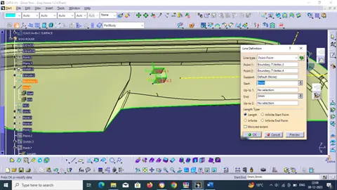
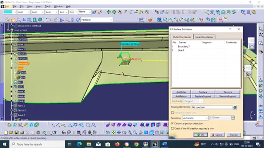
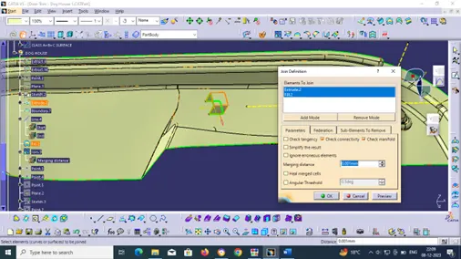
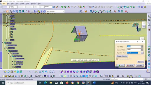

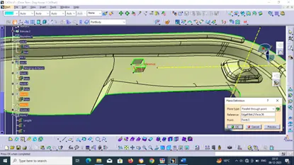
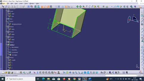
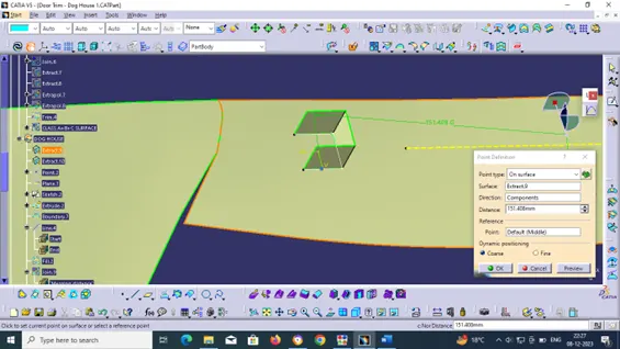
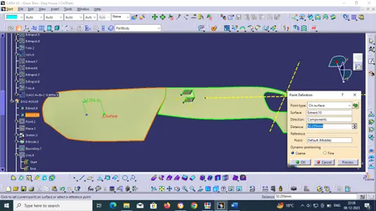
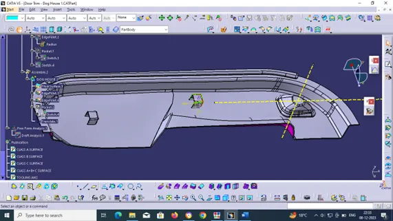
VIEW
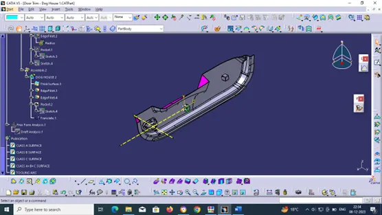
ISOMETRIC VIEW
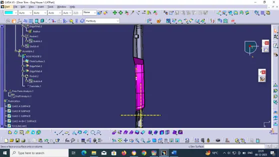
TOP VIEW
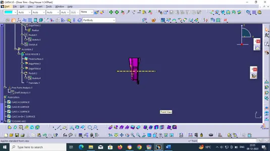
FRONT VIEW
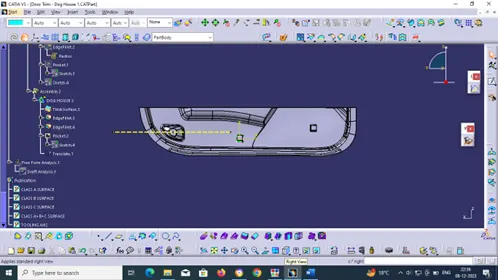
RIGHT VIEW
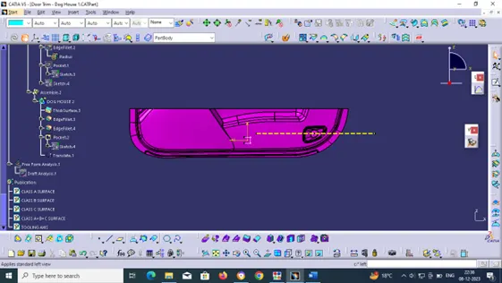
LEFT VIEW
DRAFT ANALYSIS
A SURFACE
SOLID SURFACE
SIDE AXIS TOOL
TREE STRUCTURE
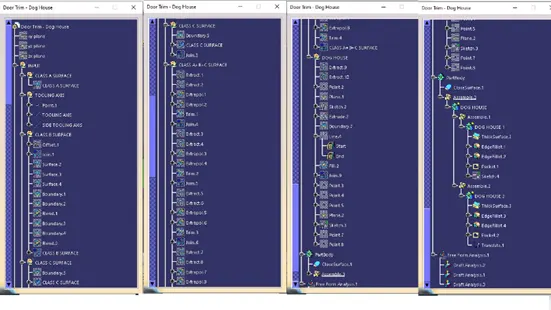
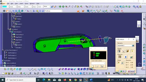
I have successfully created CLASS B and C surfaces using the given CLASS A surface of the door trim created main and side core tooling axes. Performed draft analysis the final component and the dog house.