Week 10 - Challenge 2- Attachment Feature Creation (Dog House)
AIM
To Create the Dog House for the Door Trim considering the design rules through the given Class-A surface.
THEORY
Tooling Axis
Tooling Axis is the direction in which the mold or core and cavity opens and closes. While designing a component first thing is to define the tooling axis.
Procedure
- Check the connectivity of given Class A Surface i.e no gaps between the surfaces.
- Analyse the component along x,y,z direction and check which is the best possible tooling direction (Here Y)
- Create a point at flat surface by extracting it.
- Draw a line perpendicular to extracted flat surface through the point and that is the tooling axis.
Class A Surface
Make the specified surface continuous by using the Join or Boundary commands.
Make a tooling axis if the A surface is gap-free.
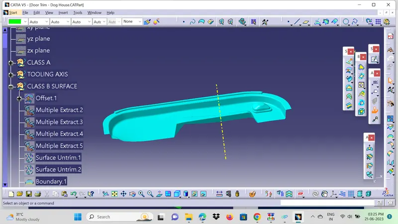
Tooling Axis
By manually adjusting the compass, determine which direction will result in the best tooling.
Through analysis, it was discovered that using the y-axis as the tooling direction would enable easy clearance of most faces.
Now choose any surface and mark the middle of it.
Then draw a line on the point and direction along the y-axis to create a fake axis.
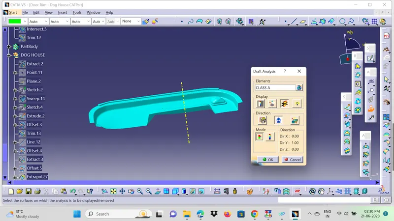
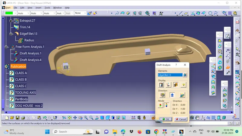
To determine whether the specified axis passes the draught analysis, perform the analysis. Otherwise, make a new tooling axis.
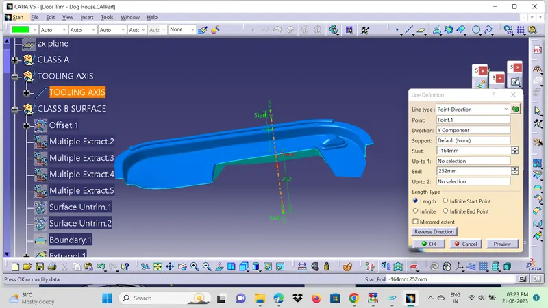
Draft Analysis of Class A
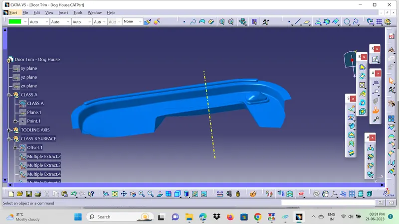
Class B Surface
Class-B surface refers to a part's thickness that is both inside the region and not visible. In other words, a surface that is classified as Class B is one that is inside Class-A. This is the area of a model where the engineering components are located.
Make the CLASS-A offset surface about 2.5 mm inward.
Using extract, multi-extract, and multi sections surfaces, check for discontinuity and revise the offset surface.
Join the surfaces together, making sure there are no gaps in the final CLASS-B surface.
Class C Surface
The surface that Joins both Class A and Class B surfaces is considered to be Class C Surface
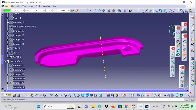
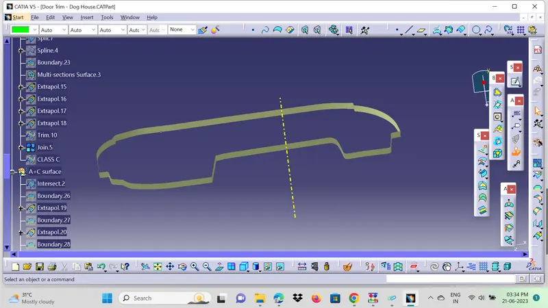
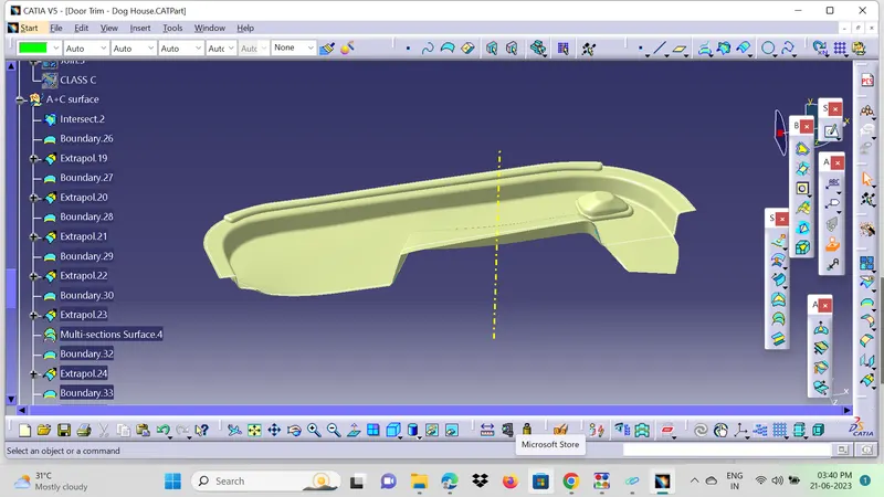
Class A+C Surface
Dog House Creation
Creating a side core axis is the first stage.
For making the side core tooling axis, I've gone with the point-and-direction method.
Make a positioned sketch on the z-x plane to create the dog house. Create the dog hose outer walls using the sweep or extrude methods.
Next, use the multi-section surface command to close the top wall.
Create a sturdy part for the dog house by using the thicken command on the part workbench.
By taking the design guidelines into account, provide correct draught angles and fillets.
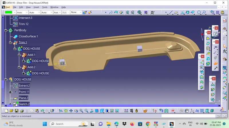
Dog House Draft Analysis
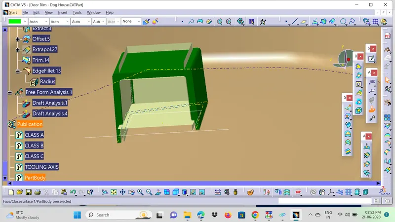
Close surface
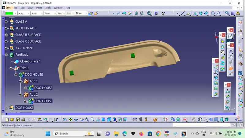
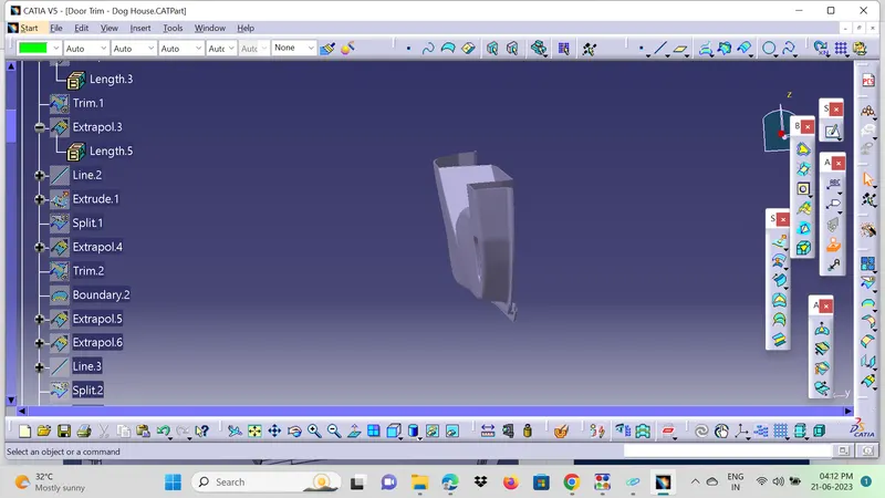
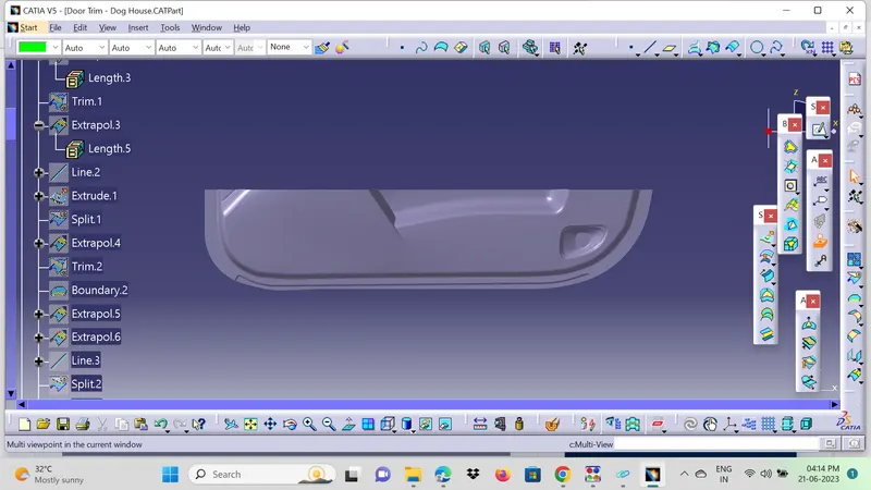
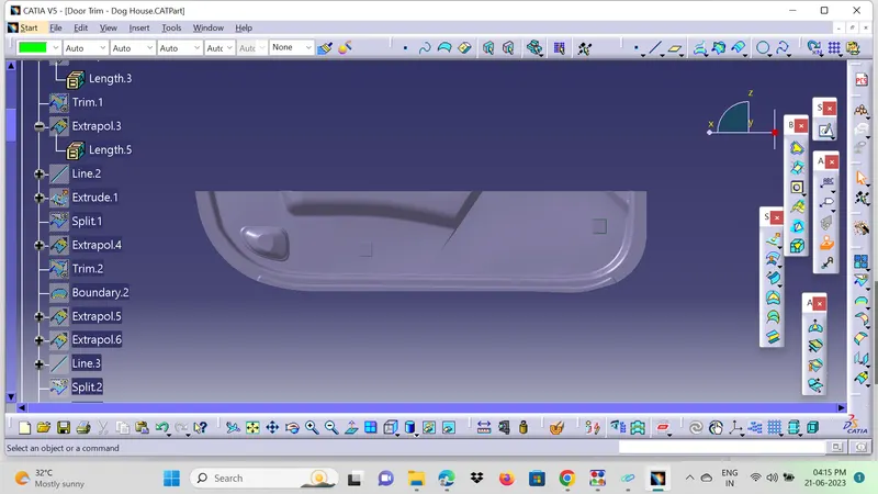
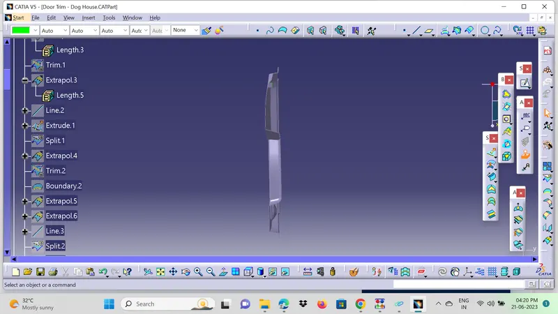
Final Component With Dog House In Various Orientations
Isometric View
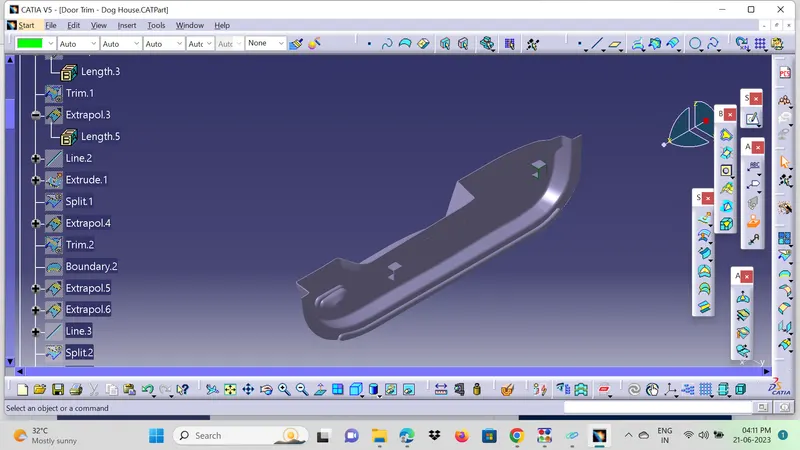
Front View
Left Side View
Right Side View
Top View
CONCLUSION
Dog House for the Door Trim considering the design rules has been created in Catia.