Midline Generation Macro
OBJECTIVE
PART A
We need to create the macro for creating midline of a tubular component like spring or pipe like componets.
PART B
Also we need to create the macro for easily create the spotwelds and save those spotwelds in a seperate collector.
PROBLEM STATEMENT
The process of creating the midline of the component using the manual process is little time taking thing if the component is big.So we need to select the pair of line starting from one end and to the other end of the components.The line selection by path option give us the smoothend midline which is not acceptable.Since this is a same kind of process repetation happens we can create a macro for this.Also the spotwelds needs to be created in the components like automobile components are quite huge in number , in such cases the manual creation of spotwelds are same kind of operations we done to create the spotwelds.So a macro is worth having for these processes.
TCL CODE EXPLANATION
PART A
*clearmarkall 1 ;
*clearmarkall 2 ;

*createlistbypathpanel lines 1 "Select the lines on one side of the tube"
set a [hm_getlist lines 1]
*createlist nodes 1
*createlistbypathpanel lines 2 "select the lines on the other side of the tube"
set b [hm_getlist lines 2]
*createlist nodes 2

foreach i $a j $b {
*linescreatemidline 1 1 2 2

}

*createmark surfaces 1 "displayed"
*maskentitymark surfaces 1 0
*createmark lines 1 "displayed"
set l [hm_getmark lines 1]
*linecombine $l $l
*unmaskall2
First clearing of the two mark id s
*clearmarkall 1 ;
*clearmarkall 2 ;
*createlistbypathpanel lines 1 "Select the lines on one side of the tube"
As we know this will ask for the user to select the lines by the path option as default
set a [hm_getlist lines 1]
This will save the line id into the variable a
*createlistbypathpanel lines 2 "select the lines on the other side of the tube"
set b [hm_getlist lines 2]
Similar set of codes for requesting the user to select the other side lines to take the midline
*createlist nodes 1
*createlist nodes 2
This is empty mark of nodes since we need this nodemark in the linecreatmidline command.which is basically the starting and the ending point of the line if we wish to take the midline of the partial part of the lines.As we need to get the midline of the entire line we are creating a empty list of nodes.
As the line id are saved as a list w enee to go for a foreach loop to create the midlines of the correct set of lines in proper order.
foreach i $a j $b {
*linescreatemidline 1 1 2 2
}
Foreachhloop will make sure that the i and j take the values of the variables a and b respectively with one value at a time an it executes the *linescreatemidline command .This will basically takes the midline of the set of the lines in list ids 1 and 2. And the other 1 and 2 as the inputs represents the empty list of nodes.
Since the midlines are formed part by part we need to combine those lines to get the complete line.So first we need to get the id of the lines formed .Since the lines formed inside the component we ned to mask those component surfaces and then we can create a mark of line with the option as "displayed".
*createmark surfaces 1 "displayed"
*maskentitymark surfaces 1 0
*createmark lines 1 "displayed"
set l [hm_getmark lines 1]
Then the hm_getmark can retrieve the id of the lines in the midline as a list.
*linecombine $l $l
*linecombine command is used to join the lines using the two line id's .So we provide the id's as $l where l is the variable containing the ids of the midline.
*unmaskall2
Since we already masked the surfces we need to unmask those .that is carried by the command *unmaskall2.
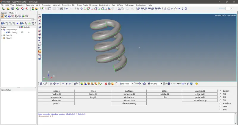
Fig 1.1 Spring model imported in HM
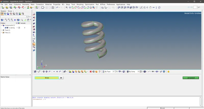
Fig 1.2 Code asks for the selection of lines with default by path option activated
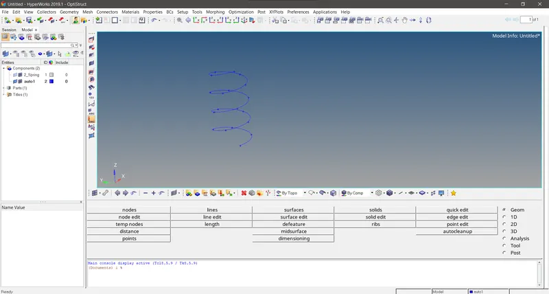
Fig 1.3 Midline generated
PART B
*clearmarkall 1 ;
*clearmarkall 2;
*createlistbypathpanel nodes 1 "Select the source nodes"
set a [hm_getlist nodes 1]
*createlistbypathpanel nodes 2 "Select the destinatn nodes"
set b [hm_getlist nodes 2]

foreach i $a j $b {

*elementtype 5 1
*rigid $i $j 123456

}

set name [hm_getstring component_name "Enter the component name to which the spotwelds needed to be organized"]

proc collector {a} {

*createentity comps includeid=0 name=$a

*createmark elements 1 "auto1"
*movemark elements 1 $a
*createmark comps 1 "auto1"
*deletemark comps 1
}
collector $name;
*createlistbypathpanel nodes 1 "Select the source nodes"
set a [hm_getlist nodes 1]
*createlistbypathpanel nodes 2
set b [hm_getlist nodes 2]
As we know this asks the user to selcect the set of nodes using the graphic panel window.First ask the user to select the set of source nodes and then destination nodes and the these set of nodes id's will be saved in the variables a and b usng the hm_getlist command.
foreach i $a j $b {
*elementtype 5 1
*rigid $i $j 123456
}
Then we need to create the rigid 1D element between these nodes.for that the command is *rigid .But we need to execute the code for the entire set of selecte nodes in order.So we use the foreach loop. And the 123456 measn the entire degrees of freedom are arrested for the rigid element.
set name [hm_getstring component_name "Enter the component name to which the spotwelds needed to be organized"
As the spootwelds are created we nee to move them to the collectorafter creating one.For that first we need to get the input from the user.This input must be thrown as the input of the component collector formation procedure.
proc collector {a} {
*createentity comps includeid=0 name=$a
*createmark elements 1 "auto1"
*movemark elements 1 $a
*createmark comps 1 "auto1"
*deletemark comps 1
}
collector name;
*createentity comps includeid=0 name=$a
This will basically creates a component collector with the name input by the user.
*createmark elements 1 "auto1"
*movemark elements 1 $a
*createmark comps 1 "auto1"
*deletemark comps 1
A mark is created on the elements in component auto1 and the elements moved to the newly formed collector by *movemark command and then again the auto1 component is marked and then delete that mark.
*movemark elements 1 $a
This command with the first input as the mark id in which the elements are stored and the second inpt is the name of the component in which the elements needs to be moved.
Then we call the function collector name , as the input.
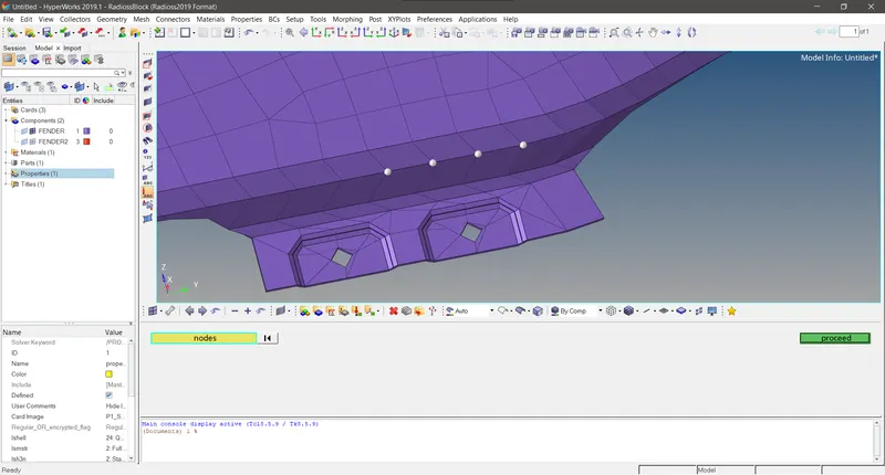
Fig2.1 Code asks the use to select the source nodes
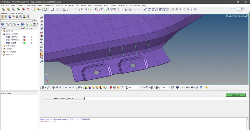
Fig 2.2 Spotwelds are formed in auto1 component and code aks for the component name for new collector creation
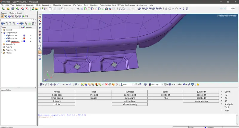
Fig2.3 After the creation of component spotweld and the spotwelds are organized to this collector
CONCLUSION
This two macros will be a great use when we work on the large components with numerous assemblies and having a lot of parts , and the connections of the sheet metal parts are done by using the spot welds and the interconnection of th parts in the entire automobile assembly requires a lot of spotwelds for the proper FEA representation of the vehicle .So in such cases these macros will help us a lot from the heaadache of creating collectors and organisinf it, creating spotelds etc..