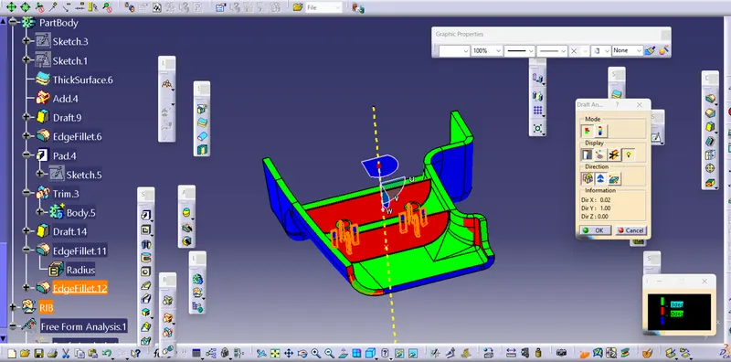
Week 10 - Challenge 1- Attachment Feature Creation (Ribs & Screw Boss)
Tooling Axis
Tooling axis is a direction in which core and cavity opens and closes. Draft angle is provided with respect to the tooling axis.
Tooling Axis created using Bisecting Method
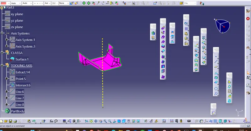
DRAFT ANALYSIS OF CLASS A SURFACE
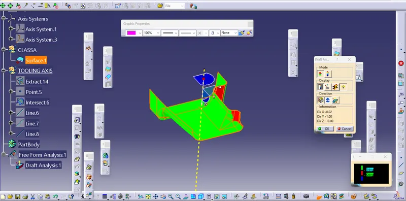
Green colour - above 3 degree positive draft
Red colour -between 3 and 0
blue colour- below 0 degree
View changed to material mode
CLASS B SURFACE
B SURFACE is created by Offseting the class-A surface to 3mm inward direction.
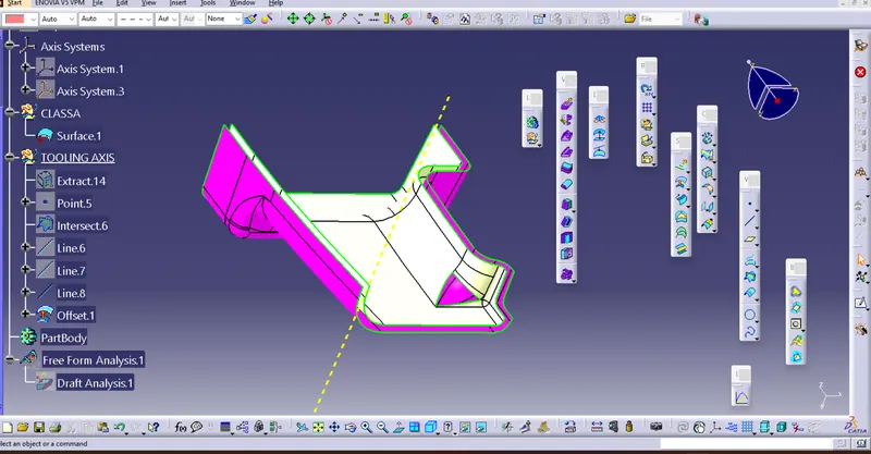
Patches are created while offsetting the surface. Rework on the patches using the features fill surface.
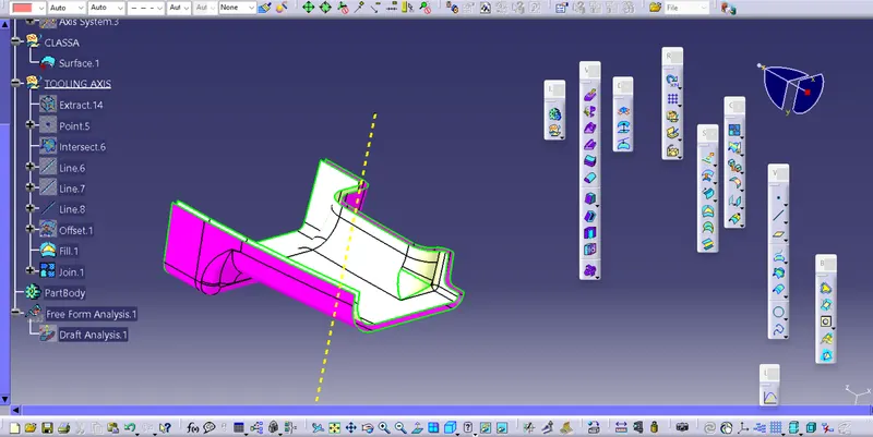
The surface that joins class-A and class-B surfaces are class-C surfaces.
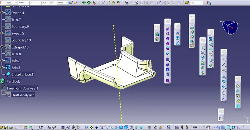
SOLID SURFACE FORMED
Close Surface feature usedto make a solid body from the surface.
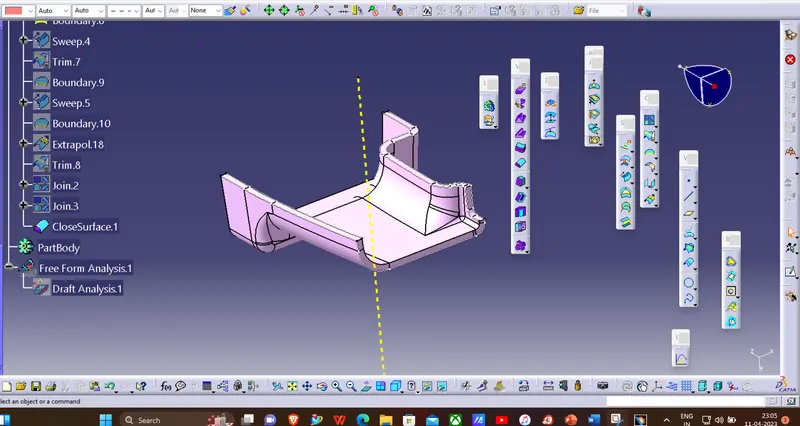
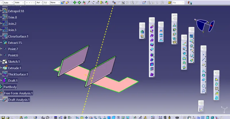
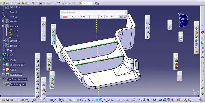
RIB DESIGN
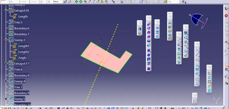
Extruded with Height - <=5t (thickness of part)
Thickness = 0.4t (thickness of part)
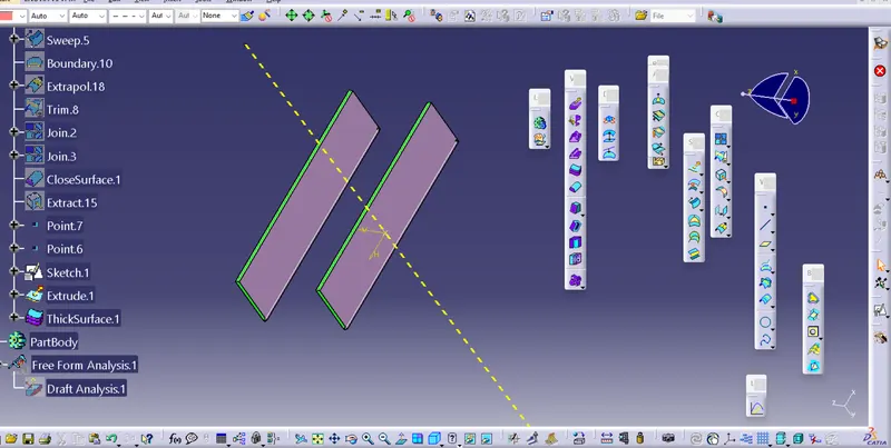
Rib draft >= .5degree
SCREW BOSS
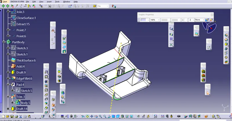
Sketch is created the diameter taken (M6 bolt) 5.2mm.
The outer diameter
Thickness - Typically 40%* of the nominal wall at the base in one side
40% of 3=1.2mm one side =7.6mm
DRAFT ANALYSIS OF COMPONENT