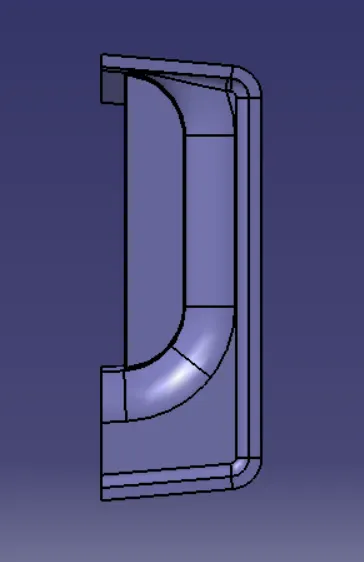
Week 10 - Challenge 1- Attachment Feature Creation (Ribs & Screw Boss)
DRill HANDLE
AIM:
To create a plastic Drill Handle component with Ribs&Screw Boss design through the given CAT Part file from Class A surface.
OBJECTIVES:
- To create the Drill Handle component from the given Class A surface.
- To create the tooling axis from the given surface to meet the requirement of the Draft angle.
- To create the Class-B and Class-C surfaces compared to the Class-A. And join the Class A, B, and C surfaces into a single closed surface.
- To create a Ribs and Screw Boss for the Drill Handle considering the design rules.
CLASS-A SURFACE:
Class A is an aesthetic finish with the highest quality finish. Most Class A surfaces for automotive components are created using Autodesk Alias based on final concept sketches. All Class A surfaces must have "curvature continuity". That is, continuity between surfaces must have the same boundaries. It is used as a reference for automotive plastics designers to create "Class B" and "Class C" finishes.
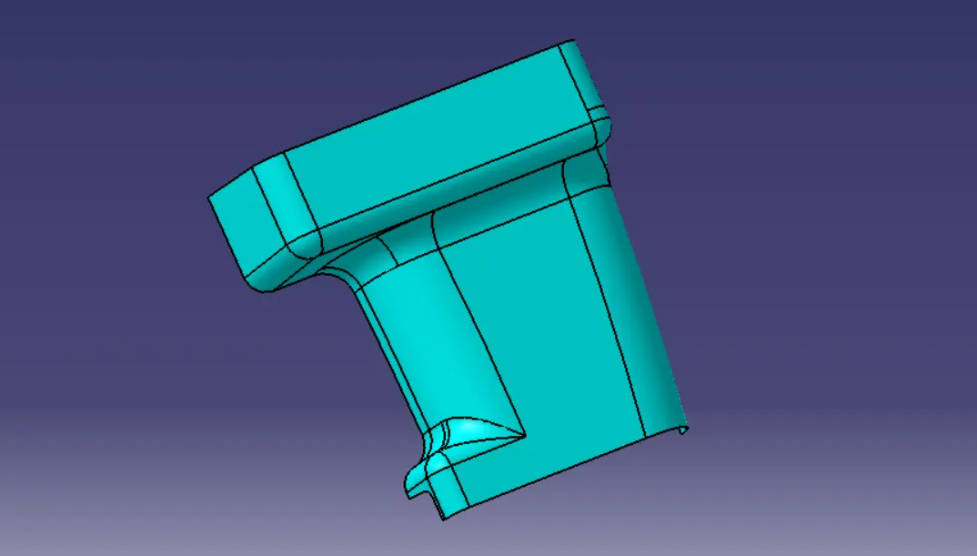
TOOLING AXIS:
The tooling axis defines the direction in which a mold or core and cavity open during the molding process. It's essentially the direction of the molded part's "pull" or "draft" away from the mold. To define the tooling axis, you typically need to identify a point and a direction or create a line that represents the tooling direction.
This axis is crucial for draft analysis and plastic component design.
The Tooling Axis is created from the X Direction on the Class A surface:
- The center point is created using the point on the base surface at 0mm.
- At this point, the axis system is created
- After pointing to the surface to draw a line, the line is created from the point to the Y Direction.
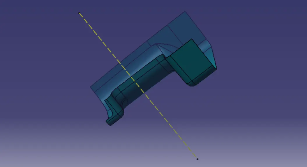
CLASS-B SURFACE:
A class B surface is below a class A surface at a certain thickness. It is created using structural principles consisting of all necessary features such as ribs, bosses, and snaps. This surface is invisible to an outside observer.
Creating Class-B Surface:
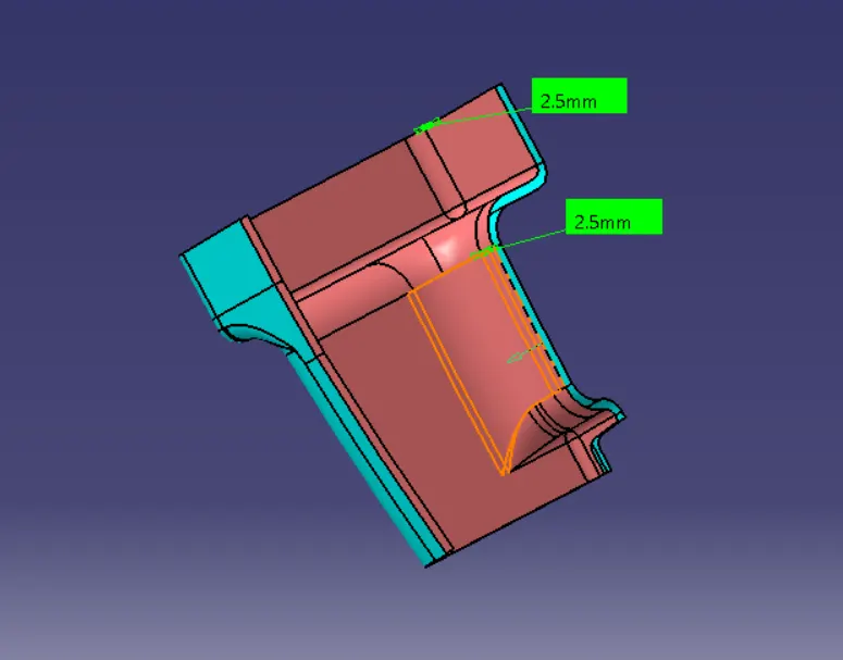
- Offset the class-a surface to 2.5mm(thickness)
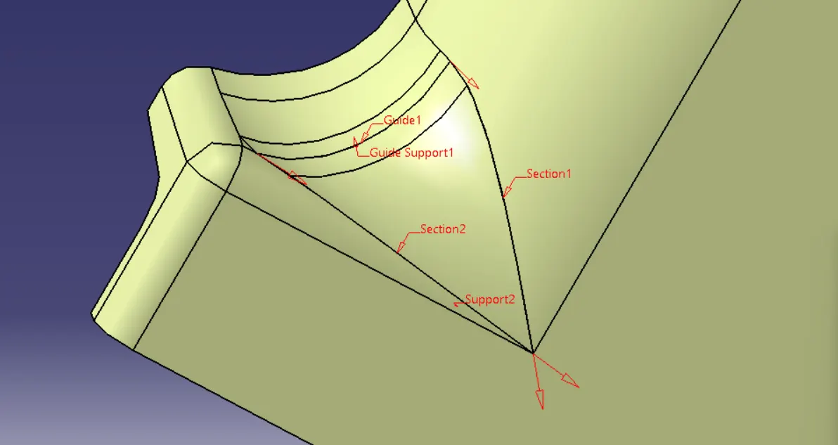
- Fill the patches that are not offset using the commands Extract, Boundary, and multi-section surface.
- Then join the patches to the offseted surface using the command.
- To check the final surface using the boundary.
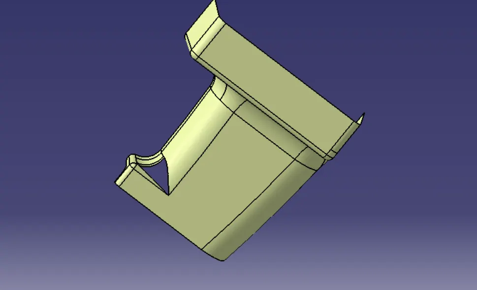
Patches:
Final surfaces of Class-A and Class-B, with 2.5mm thickness.
CLASS-C SURFACE:
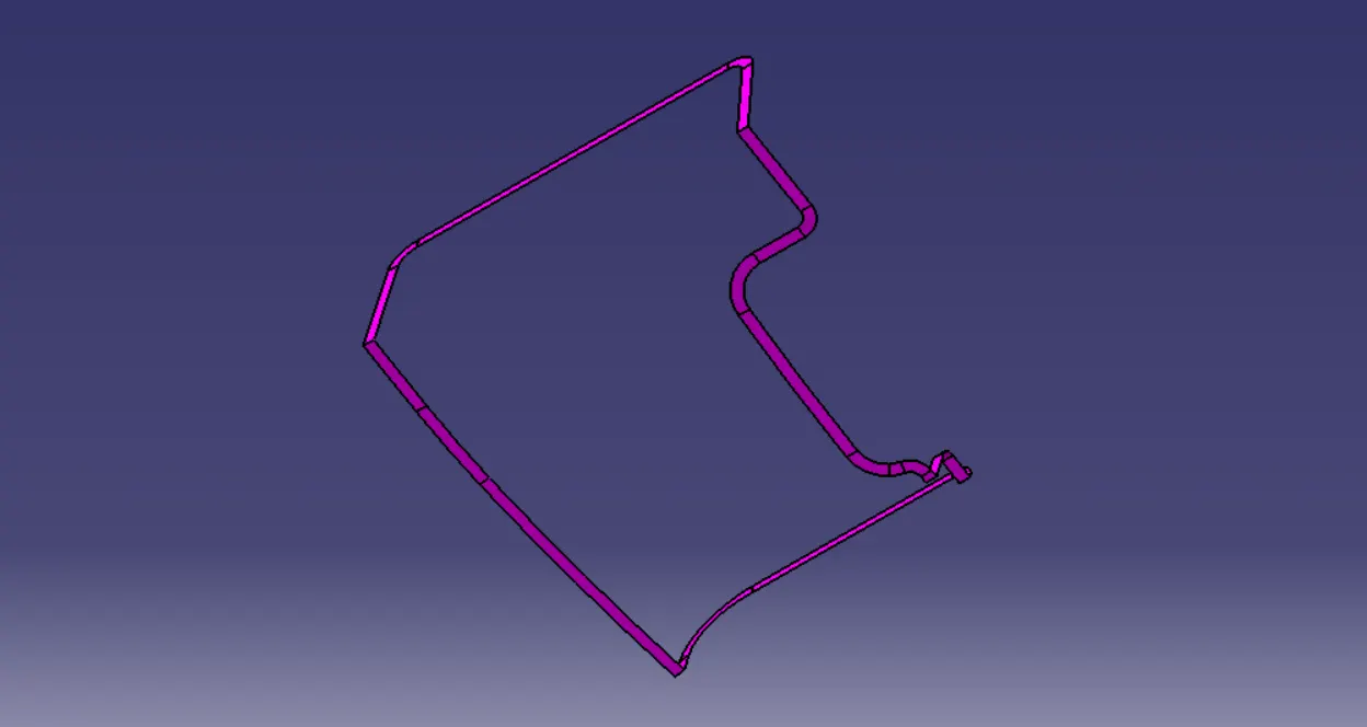
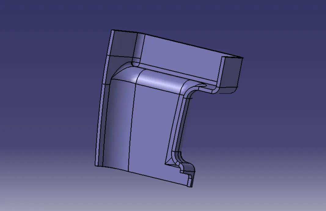
A class C surface is a surface created to connect class A and class B surfaces
- Join all the surfaces(Class-A,B,&C)
- Create a closed body surface in Part Design.
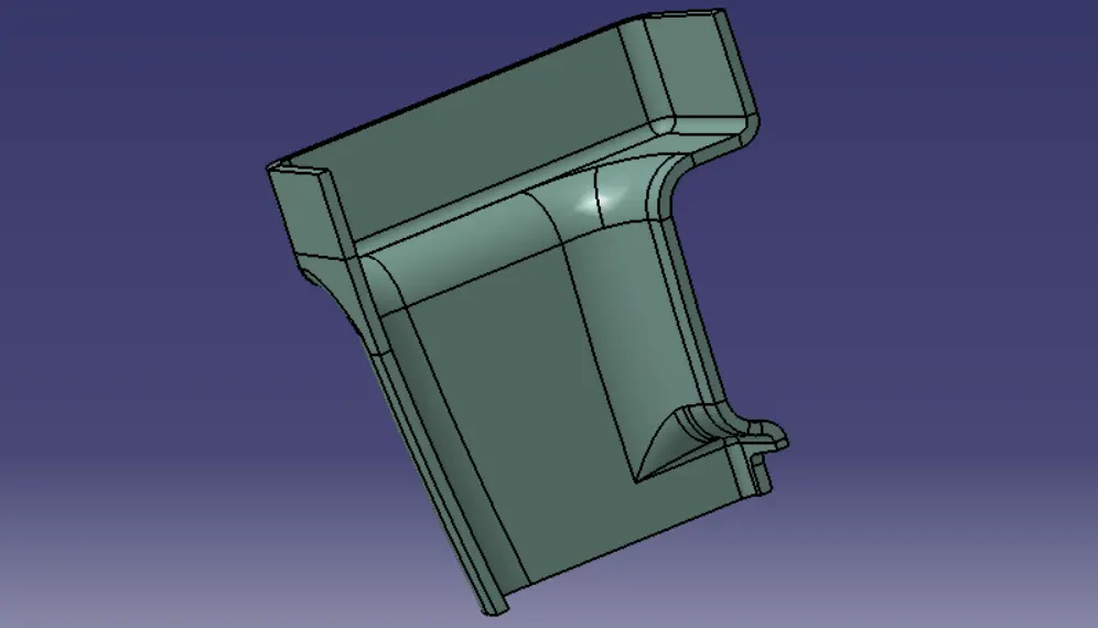
Close Body:
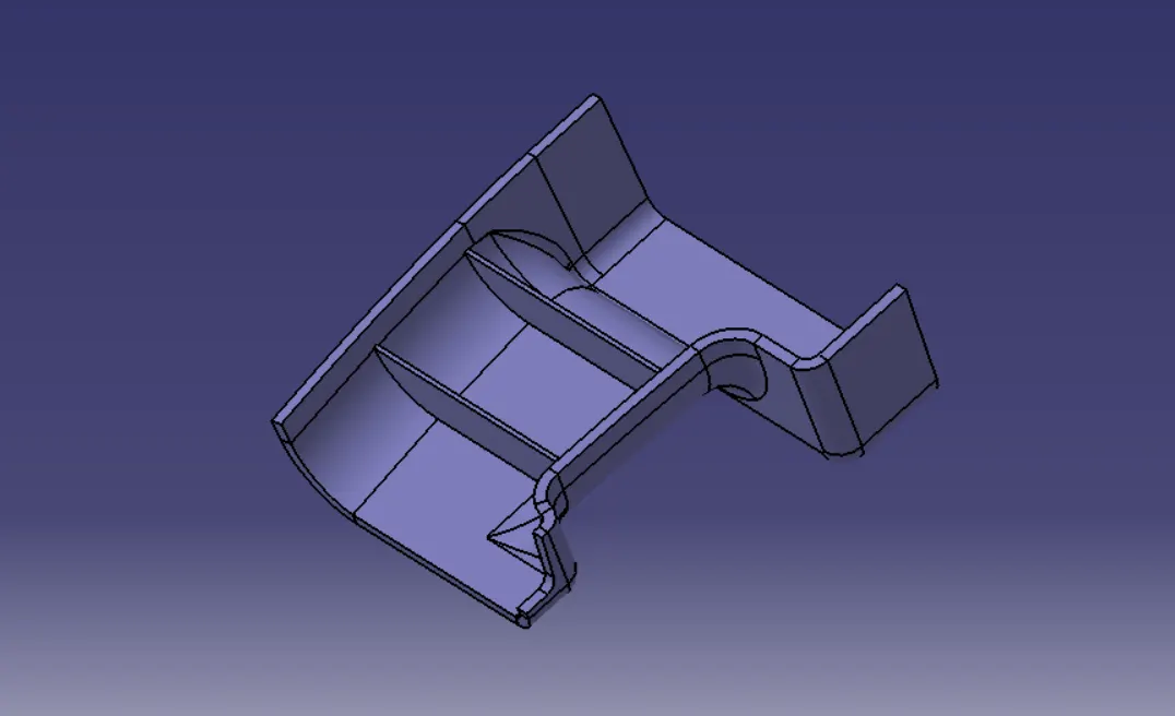
RIB CREATION:
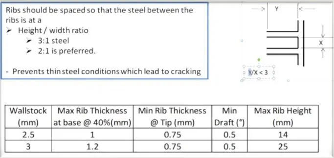
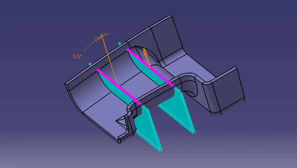
Ribs are thin, wall-like structures that add support and rigidity to injection molded parts. They are thinner than primary walls and are used to support these walls, as well as bosses, by running perpendicular to these structures. Ribs are often used to replace thick wall sections to avoid sink marks, warp, and voids. By placing ribs in a load-bearing direction, such as long unsupported stretches of your part, instead of making a section thicker, you can retain the support and rigidity you want and eliminate problems caused by thick walls.
Design rules for Rib creation:
1. Draft Angle:
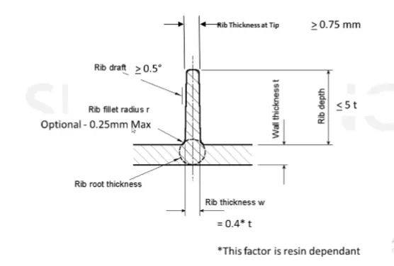
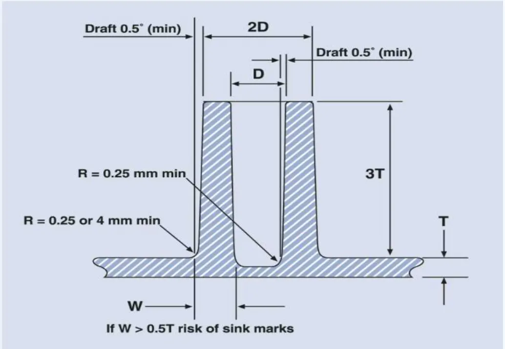
A minimum draft angle of 0.5 degrees per side is recommended for easy mold ejection.
Larger draft angles can be used if needed, but should be considered carefully to avoid excessive tapering of the rib tip.
2. Rib Height:
Rib height should typically be less than or equal to 3 times the wall thickness.
Higher ribs can be more prone to damage during ejection or use, and may create voids if the plastic cannot reach the tip.
Consider using multiple shorter ribs instead of one tall rib if needed to maintain structural integrity.
3. Rib Spacing:
The height-to-spacing ratio of ribs should be maintained within a reasonable range, typically between 2 and 3.
This helps ensure even stress distribution and prevents excessive stress concentration.
4. Rib Thickness:
Rib thickness at the base can be 40% of the wall thickness.
For wall thicknesses less than 1mm, the rib thickness should be the same as the wall thickness.
Minimum thickness at the rib tip should be 0.75mm.
5. Rib Root Thickness:
Maintain a consistent rib root thickness by creating a tri-tangential circle at the base of the rib.
The diameter of this circle should fall within the allowed range for the rib's root thickness.
6. Rib Base Fillet Radius:
A nominal base fillet radius of 0.125 times the wall thickness is recommended.
The maximum fillet radius allowed is 0.25 times the wall thickness.
7. Rib Connection:
Ribs should be connected to other structural features wherever possible to maximize support and prevent stress concentration.
Ribs on opposite sides of the wall should be offset to avoid stress concentration.
8. Other Considerations:
Material Properties:
Consider the material being used when designing ribs, as different materials have different strength and stiffness properties.
Manufacturing Process:
Ensure that the ribs can be easily manufactured using the chosen process, such as injection molding.
Stress Analysis:
Perform stress analysis to ensure that the rib design can withstand the intended loads.
SCREW BOSS:
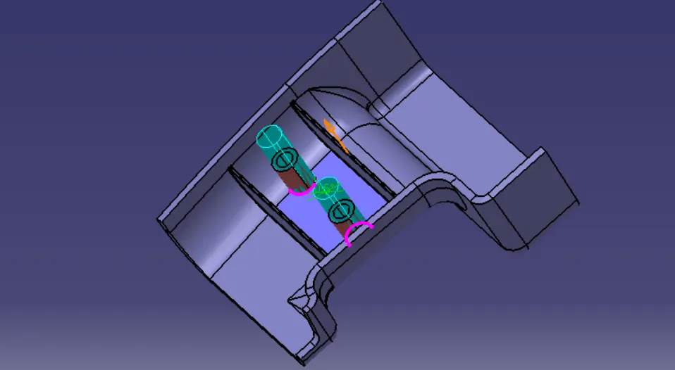
In plastic injection molding, screw bosses are cylindrical protrusions on a part that provide a secure connection for screws or other fasteners. They are created during the molding process using a mold core pin, forming the desired cavity. Screw bosses play a crucial role in aligning parts, facilitating fastening, and enhancing the structural integrity of the plastic component.
Design rules for screw boss creation:
- Draft:
A minimum draft angle of 0.5 degrees is recommended on the outer diameter of the boss to allow easy ejection from the mold.
A draft angle of 0.25 degrees is recommended on the inner diameter (ID) of the boss.
- Thickness:
The boss wall thickness is typically 40% of the adjacent wall thickness.
Some resources recommend the boss wall thickness to be between 40 and 60% of the adjacent wall thickness.
Boss thickness should provide at least 60% of screw thread length with something to catch on.
- Height and Diameter:
The height of the boss should be sufficient to accommodate the screw head and washer, typically 1.5 to 2 times the screw diameter.
The height-to-diameter ratio of the boss should be less than 3:1.
- Radii:
Maximum radii at the base of the boss are typically around 0.25mm.
The radius at the base of a hole in the boss should be between 0.25 and 0.5 times the nominal wall thickness.
- Spacing:
The spacing between bosses should be at least twice the nominal wall thickness to avoid thin sections and potential cooling issues.
The distance between ribs (if used) should be in a 3:1 ratio (rib height divided by 3) to prevent thin walls and cracking.
Additional Considerations:
- Placement:
Distribute the boss placement to avoid thin walls and hot spots during cooling.
Consider placing bosses close to thicker walls.
Try to place bosses on the interior area of the part to minimize sink marks.
- Cosmetics:
Avoid thick sections on exterior walls to minimize sink marks.
- Cooling:
Bosses often have thicker dimensions, which can prolong cooling times compared to thinner sections.
Ensure adequate cooling time to avoid variations in cooling and hot spots.
- Material Selection:
Consider material properties and their impact on boss strength and assembly.
- Assembly:
Ensure that the boss diameter is at least 2.5 times the screw diameter to provide adequate support
DRAFT ANALYSIS:
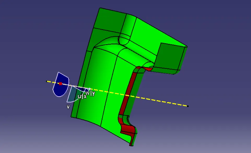
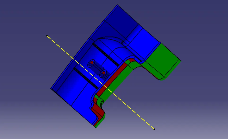
Draft analysis enables you to detect that the part we drafted will be easily removed. This type of analysis is performed based on color ranges, identifying the zones on the analyzed element where the deviation from the draft direction at any point corresponds to specified values.
- Go to insert
- Click on the compass icon and align it with the tooling axis, and click on the surface. We will get our result
Class-A Draft Analysis:
Final Body Draft:
TREE STRUCTURE:
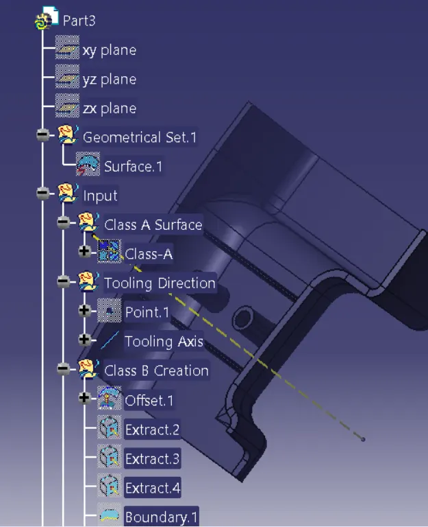
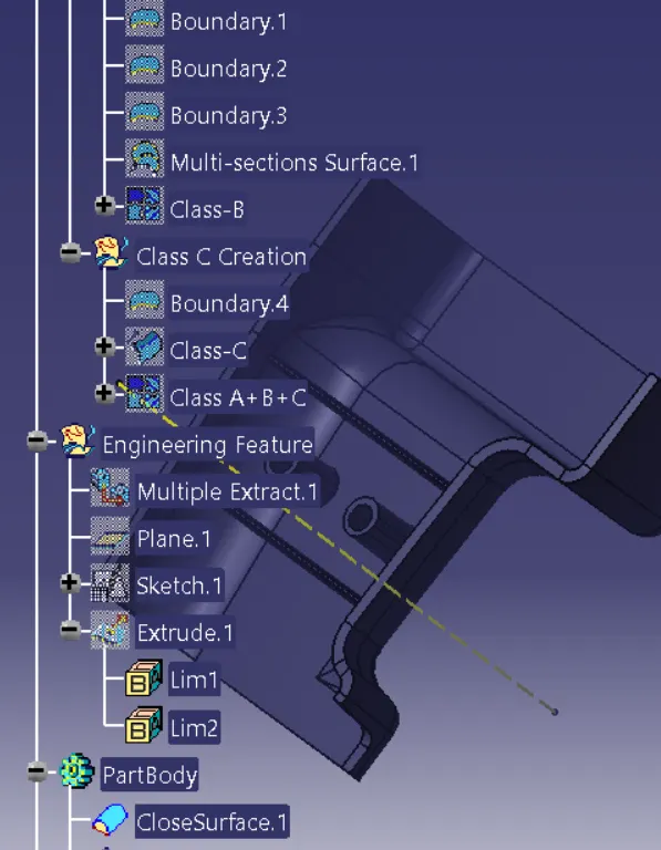
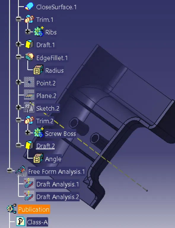
ORIENTATIONS:
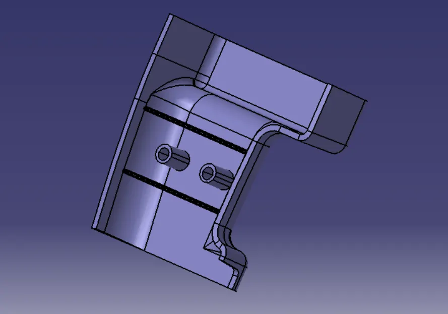
Isometric View:
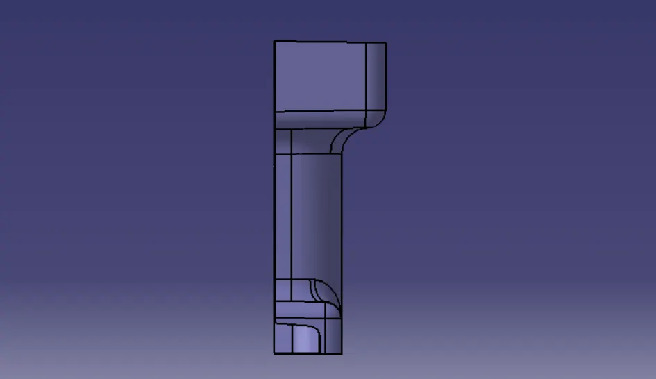
Front View:
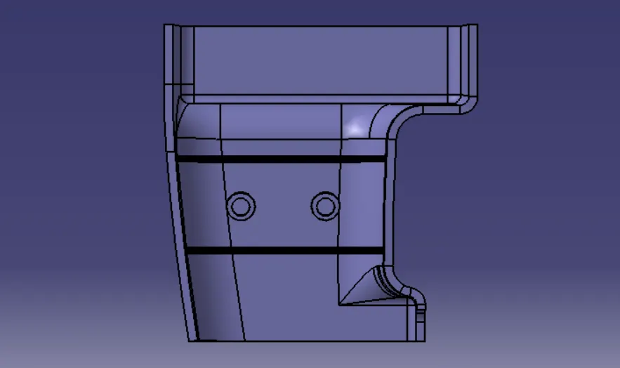
Side View:
Top View: