Week 10 - Challenge 1- Attachment Feature Creation (Ribs & Screw Boss)
RIBS AND SCREW BOSS
REPORT ABOUT TOOLING AXIS AND DRAFT ANALYSIS :-
CREATING TOOLING AXIS :-
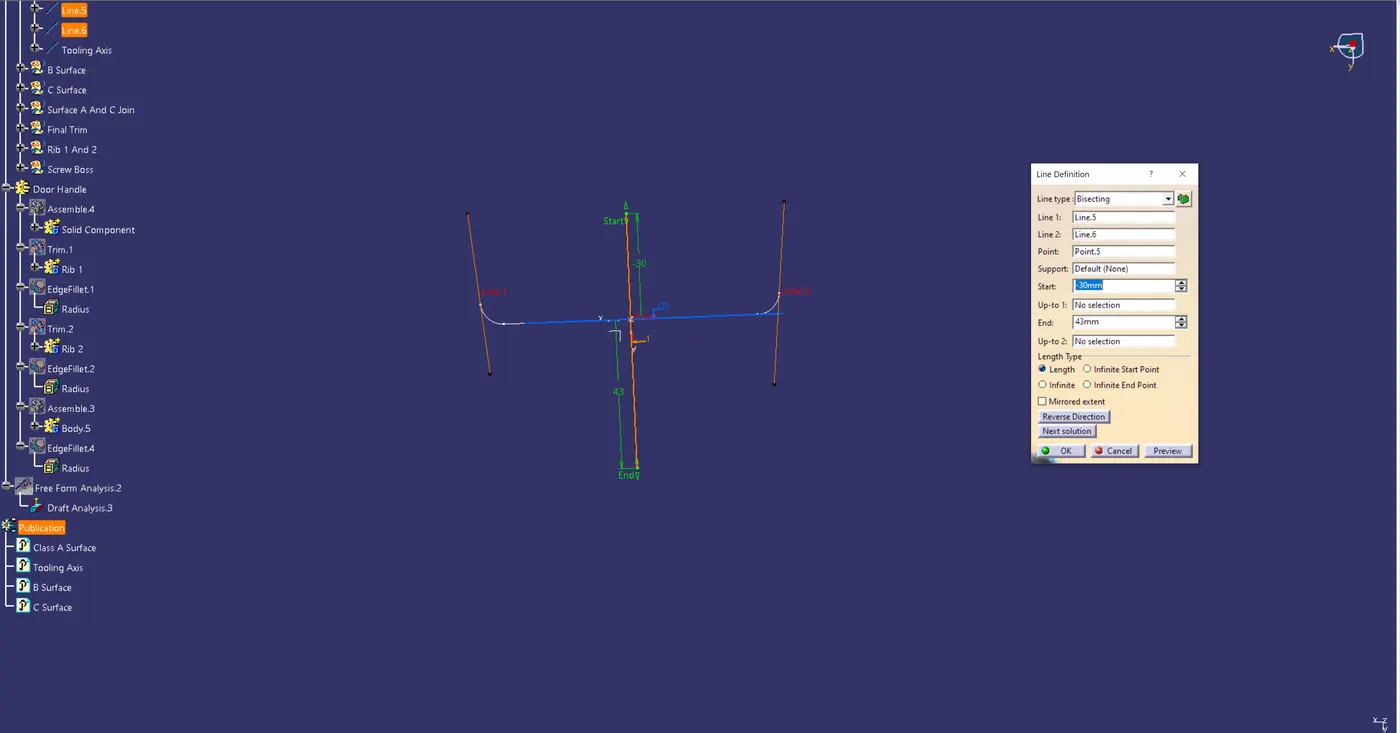
In basic terms, the direction in which the mold pulls a part is known as the tooling direction. Essentially, the mold is constructed from two distinct parts.
You have two sides: the Core side and the Cavity side. The Tooling Direction or Dye line is where the Core separates from the Cavity.
At the center of the switch bezel, create an axis system.
Find the intersection point between the class A surface and the yz plane.
On the suspected drafts, draw point-to-point lines and conceal the class A surface.
To establish a tooling axis, make a bisecting line by joining the two lines.
To obtain the precise medium from both sides and attain the highest positive draft angle, BISECTING LINES were used.
DRAFT ANALYSIS :- (ISOMETRIC, FRONT, SIDE, AND TOP VIEWS)
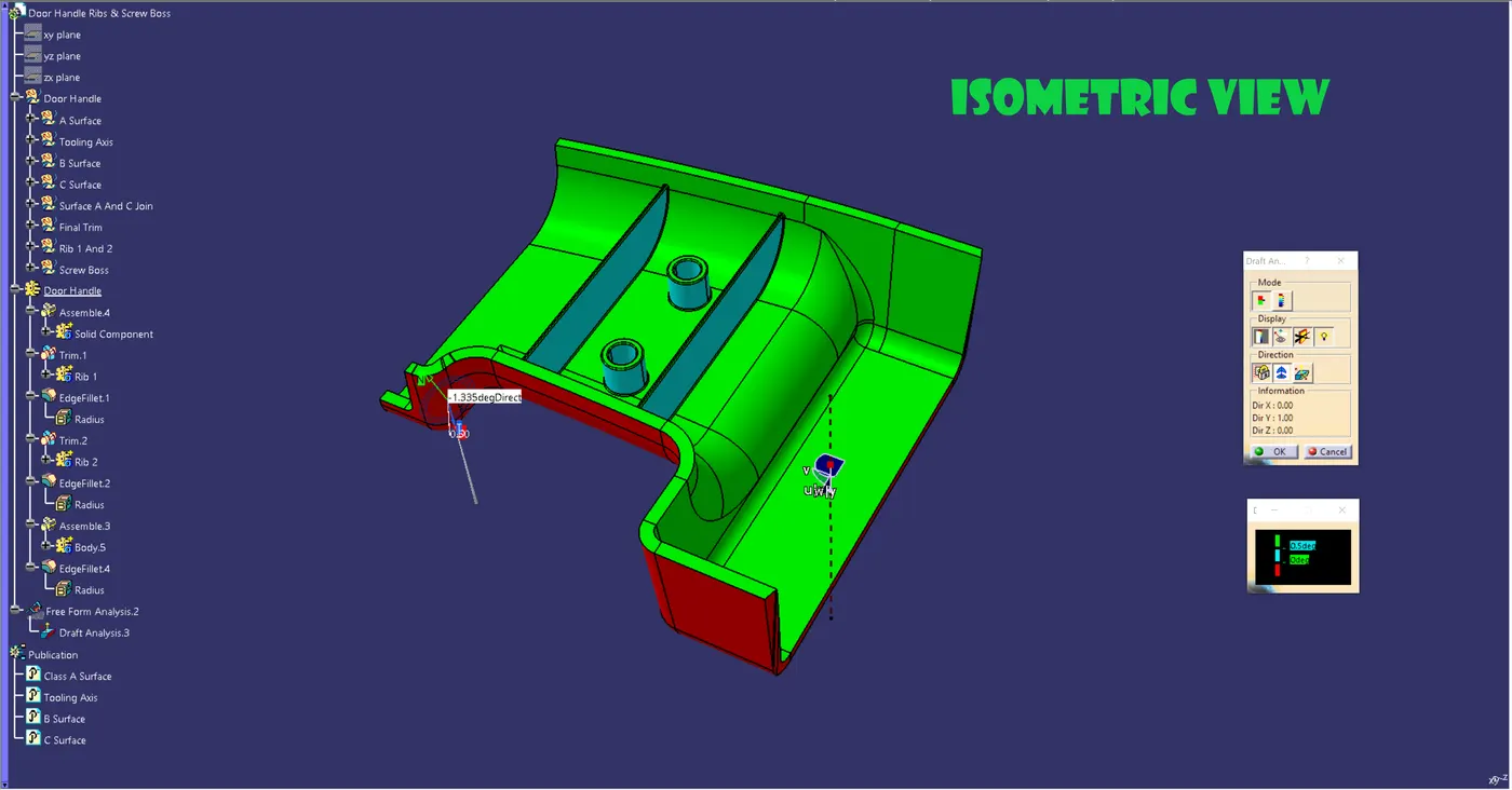
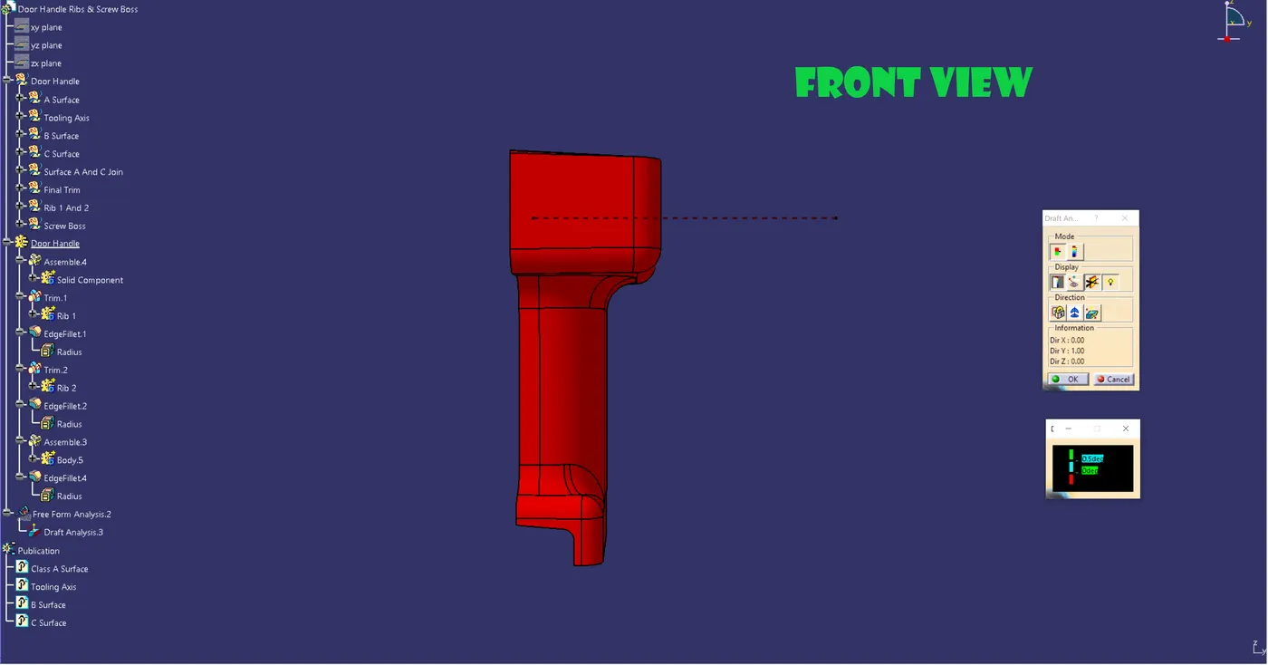
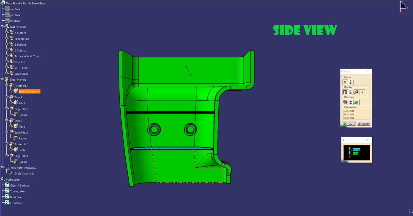
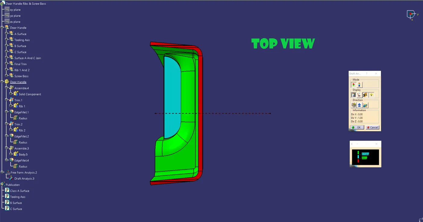
You can determine whether the part you drafted will be simple to remove with the Draft Analysis command.
Utilizing color ranges to define zones on the investigated element where the deviation from the draft direction at any given position corresponds to predetermined values,
this type of analysis is carried out.
Go to customized view parameter, select mesh, check material, and click OK before proceeding to drat analysis.
Go to insert » analysis » feature draft analysis to access the draft analyses now.
To determine the draft direction, use the compass.
As the passing draft angle is indicated, the component turns green.
To get the component's angle, use the running point.