Week 10 - Challenge 1- Attachment Feature Creation (Ribs & Screw Boss)
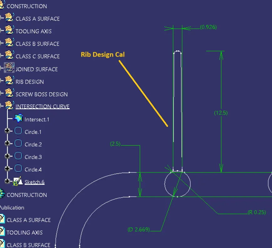
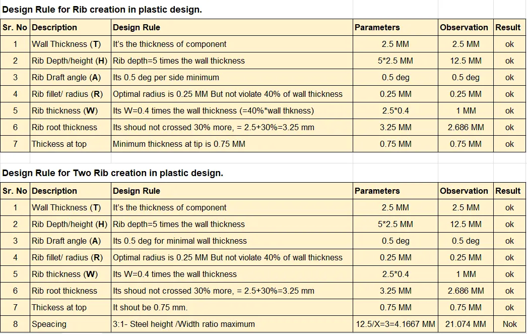
Aim:- Create the rib for the Drill Handle considering the design rules.
Objective:-
1. Create tooling axis by using bisecting method
2. Design Class B & class C surface and joined them.
3. Create solid features by surface we created.
4. Draft analysis for the given component.
5. Design of Rib's and Scrow bosses.
6. General calculations and analysis of Rib's & Screw Bosses.
1. CLASS A SURFACE
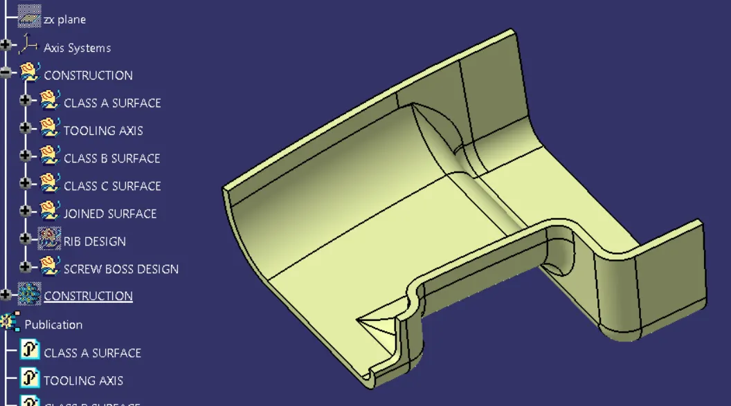
Its the given surface for creating soild features and designing the ribs and screw bosses on it.
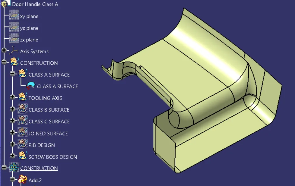
Fig:- Class A Surface
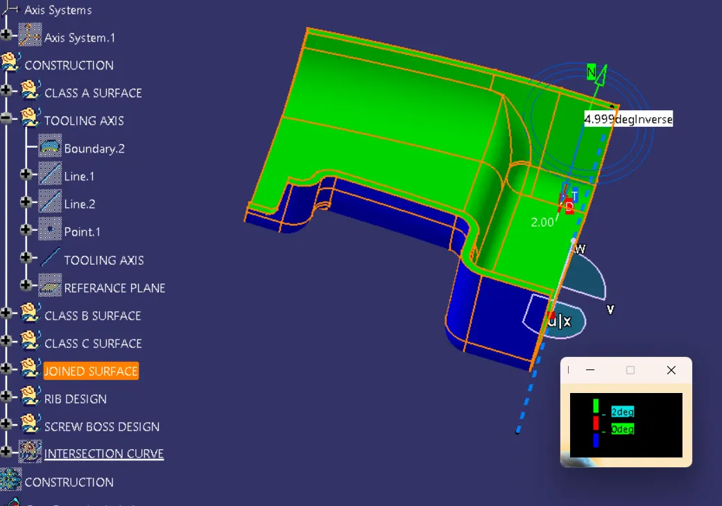
2. Create tooling axis by using bisecting method
To analyse the class A surface and select a surface in a such way that to clear the tooling directions and moled seperations. Tooling directios is the most important in plastics design as it decides the direction of the mold.
Method of creating tooling axis:-
- Reference point is first created on the extracted surface.
- New axis system is deployed to plot clearance lines.
- To draw the both side surfece line on the points.
- Create bisecting line on the given surface called tooling axis.
- The X-direction and Y-direction along the class-A were used to create the tooling axis.
- Graphic properties of the tooling axis were changed before publishing.
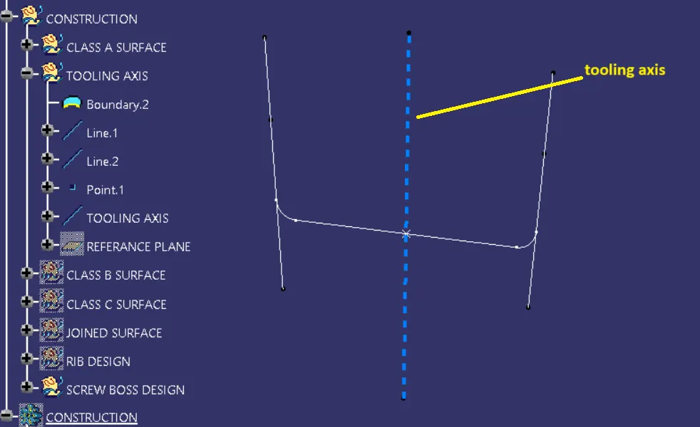
Fig:- Tooling axis.
3. Design Class B & class C surface and joined them.
1. Class B surface
Its the offset value with referance of class A surface.
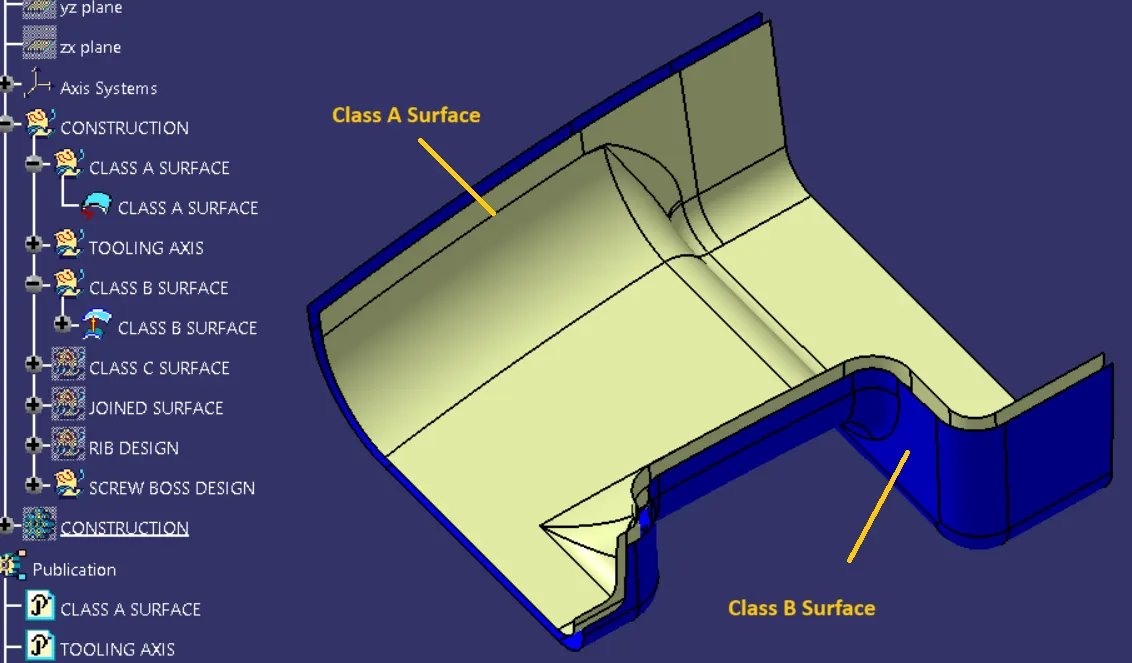
2. Class C surface
Its the the surface is used to join class A and class B surface togetherly.
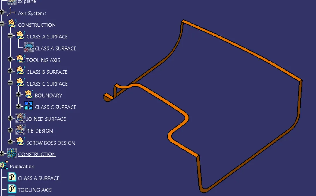
Joined surface_
3. Draft analysis for the given component.
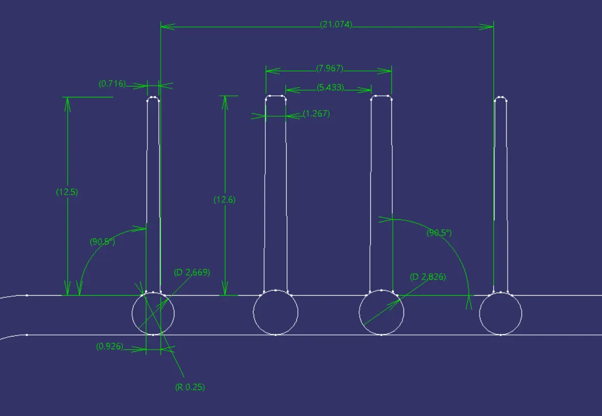
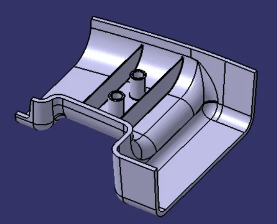
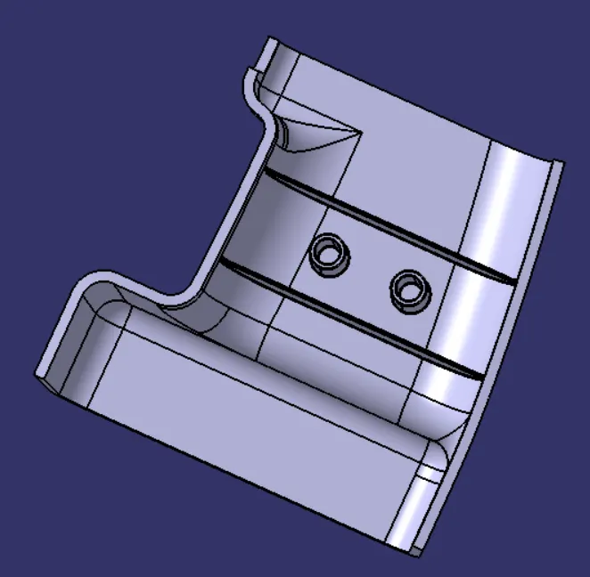
4. Design of Rib's and Scrow bosses.
Tree Diagram
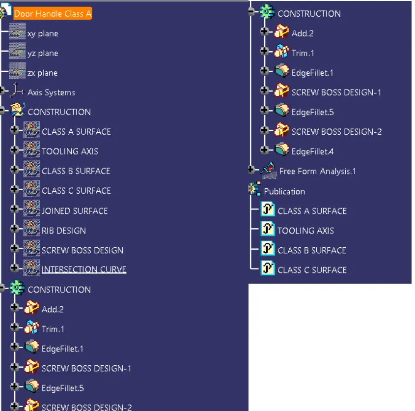
Conclusion_ In this way we have sussessfully design rib's and screw bosses design.