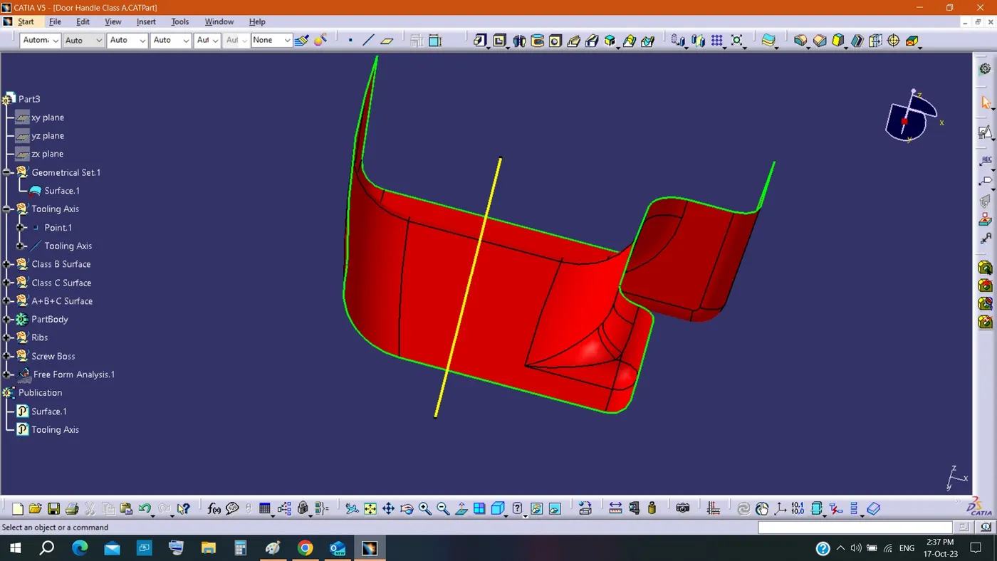
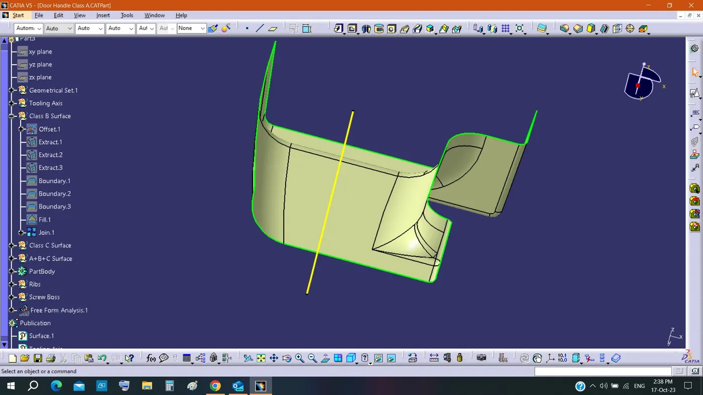
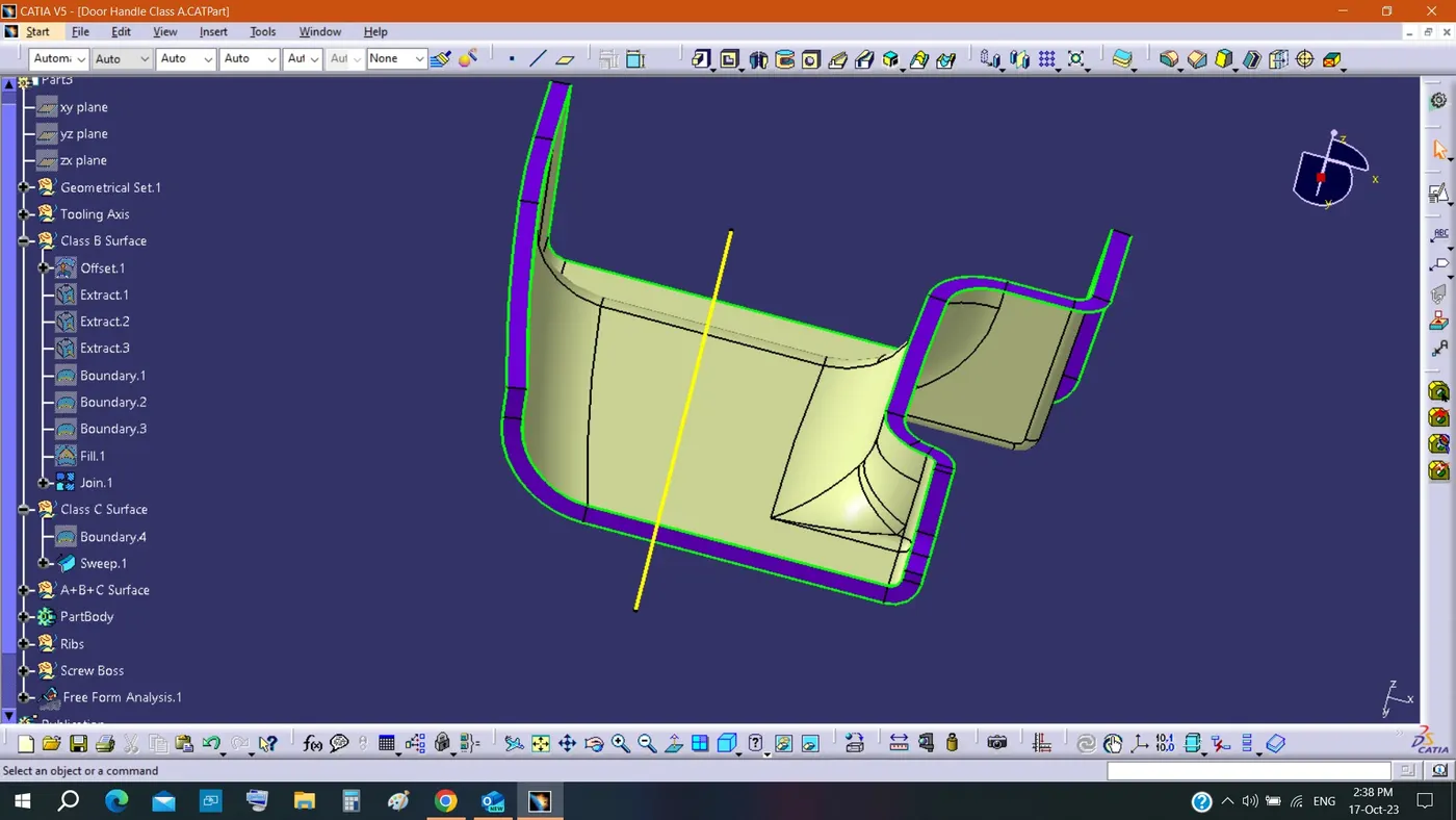
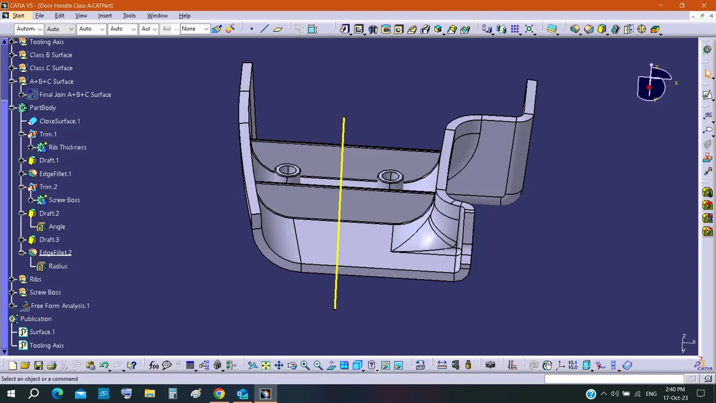
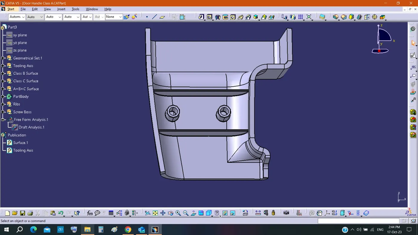
Week 10 - Challenge 1- Attachment Feature Creation (Ribs & Screw Boss)
Aim:
To Create the rib for the Drill Handle considering the design rules through the given CAT Part file from Class A surface To design a Class B & Class C Surface and final component. .
Used via
Catia V5 software- tools used given below,
• Point through on the center of the surface
• Axis creation
• Line in point direction
• Intersection
• Tool Axis
• Draft Analysis in Free from Analysis
• Boundry
• Multiple extract boundary
• Offset
• Trim
• Join
• Sweep command, particularly with draft direction
• Multisection surface
• Blend
• Fillet
• Closed Surface
Tooling Axis:
Taking the Thickness of the component to be 3 mm
Tooling axis: The direction in which the mold or core and cavity open is the tooling axis.
Tooling Direction:
The Tooling Direction is basically the direction that the mold pulls apart. The mold is built in two separate pieces, basically. You have a Cavity side and you have the Core side. The Core pulls apart from the Cavity and that's the Dyeline or the Tooling Direction. There are different methods to find out the tooling direction. Here we are using bisecting method to find out the tooling direction. We can use any method the ultimate aim is to reduce the cost of manufacturing by reducing the complicity in manufacturing the component.
PROCEDURE:
The procedure is divided into two parts first creating the tooling axis and then performing the draft analysis.
Creating tooling axis:
The first thing to do is to find out the possible tooling direction by visually checking the part. Rotate the part in all directions and find out the most suitable direction for tooling. Here in this case viewing from the Y direction we can clear the face in tooling.
Then we create a point on the surface of the part, on the hole of the headlight portion by using the fill command creating a surface.
General Guidelines for Bosses:
Draft - 0.5 degrees on the walls of boss
Thickness - Typically 40%* of the nominal wall at the base.
Height to Diameter Ratio - 3:1
Radii - 0.25mm maximum radii.
Rib & Screw Boss were made using part design following the design guidelines.
The publication is used to make easily accessible of the published components.
Draft Analysis:
• With draft analysis, you can verify draft angles, examine angle changes within a face, as well as locate parting lines, injection, and ejection surfaces in parts.
• The draft analysis button within CATIA V5 will help you quickly gather the draft angle on multiple surfaces without the need for tedious manual measurements. Here is a quick rundown of how the icon works when you have a given die direction.
• Performing the draft analysis:
o Open the Feature draft analysis option from Insert > Analysis > Feature draft analysis.
o A new window pops up by default it will be in quick analysis mode. Change the range to 2.9deg.
o Next, you have to position the compass on the tooling axis by dragging the compass from the top right corner of the working area. The W axis of the compass should be in line with the axis.
o Then you have to define the compass by clicking on the compass icon on the draft analysis window. Then lock the position of the compass by clicking the lock icon.
o After that is selected, the surface and the whole surface will show a color range. For a good draft make the surface fully green