Week 10 - Challenge 1- Attachment Feature Creation (Ribs & Screw Boss)
Attachment Feature Creation (Ribs & Screw Boss)
AIM
Create the component through the given Class-A surface.
the tooling axis for the given Class-A Surface should be created meeting the requirements of the draft angle and at the end perform the Draft analysis on the model. Create the rib and screw boss as by considering the design rules
CLASS A SURFACE
In automotive design, a class A surface is any of a set of free form surfaces of high efficiency and quality. It gives the aesthetic of the component which is created by the styling team and gives to the part design engineer to create the part with all engineering aspects.
TOOLING AXIS
TOOLING AXIS is created by bisecting the axis created on two intersections .
the best tooling direction for the class-A surface is along y-axis direction.
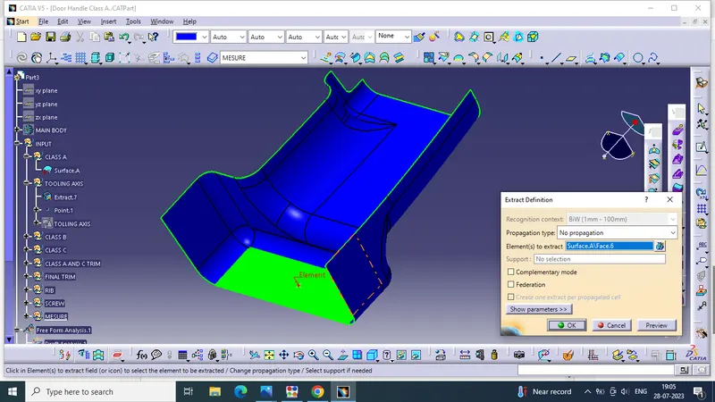
Flat surface on the center part is extracted for creating the tooling axis in y direction
Then created a with the point and direction along y axis.
.
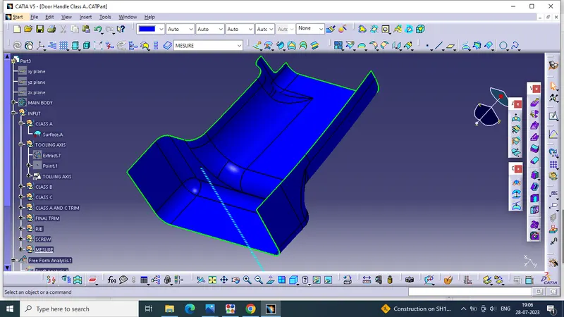
TOOLING AXIS of the part is created
DRAFT ANGLE
When developing parts for plastic injection molding, applying a draft (or a taper) to the faces of the part is critical to improving the moldability of your part. Without it, parts run the risk of poor cosmetic finishes and may bend, break, or warp due to molding stresses caused by plastic cooling. Equally important, an absence of draft may prevent parts from ejecting from the mold, damaging not only the parts but possibly the mold itself—a costly and time-consuming detour.
DRAFT ANALYSIS OF CLASS A SURFACE
draft analysis is done using featured draft analysis tool
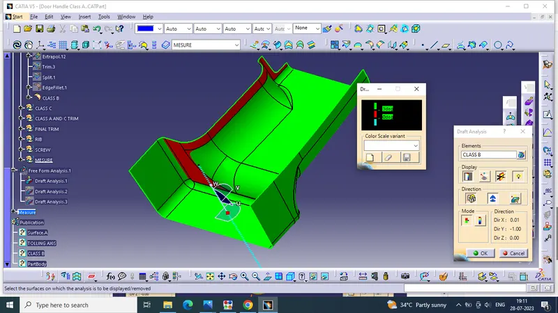
Use the compass fucnction to aling the compass to the tooling direction and lock the direction using lock function in the draft analysis tool bar
the surface is showing green colour so that the surface clears the minimum draft angle of 3 degree
By using the analyses under the running pointwe can check draft angle on the individual faces. It shows how much draft on specific points when we move the cursor point.
.
Green colour - above 3 degree positive draft
Red colour -between 3 and 0
blue colour- below 0 degree
CLASS B SURFACE
Class-B surface means the thickness of a part it is not visible and is inside part. In other words, the Class-B surface is a surface below a certain thickness from the class-A surface. This is the surface that contains engineering aspects of a model.The Class B finish is a quality finish with only minimal imperfections. A Class B finish is the most common finish for exterior surfaces. It is normally specified on surfaces such as external covers, panels, and parts that are fairly prominent.
.
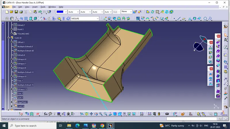
B SURFACE is created by Offseting the class-A surface to 3mm inward direction.
patches are created while offsetting the surface. Rework on the patches using the features like extract, multi-extract, sweep, trim, extrapolate.
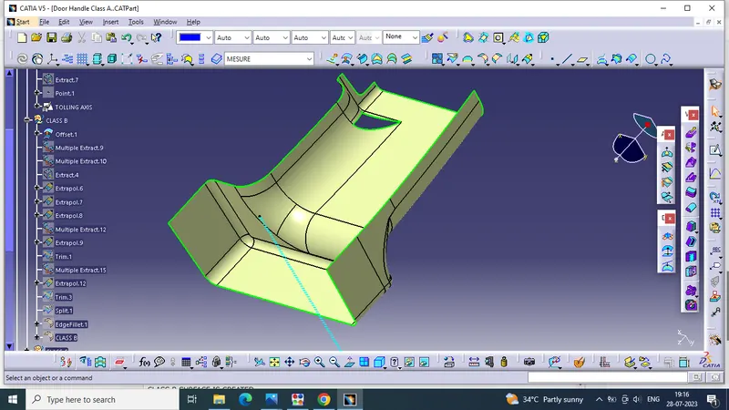
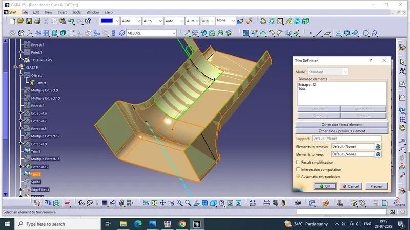
the boundary command is used to identify and highlight the patches
CLASS B SURFACE IS CREATED
.
CLASS C SURFACE
The surface that joins class-A and class-B surfaces are class-C surfaces. Class C is often specified for interior surfaces not readily visible, surfaces that will be covered by another part when assembledThe Class C finish allows more imperfections than Class A or B. Class C is often specified for interior surfaces not readily visible, surfaces that will be covered by another part when assembled, or surfaces which the Customer feels do not need to meet a high cosmetic finish.
..
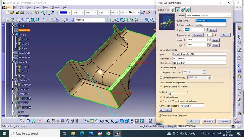
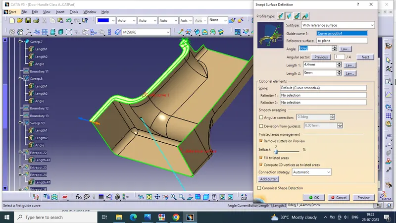
The method used for class c surface is sweep feature
Since it is a complex class-A surface, we cannot create the class-A boundary curve and sweep in a single stretch .
small sections are created using multi-extract command and then create sweep of 90 degree with reference to the surface option.
.
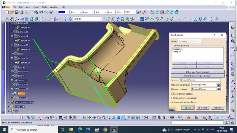
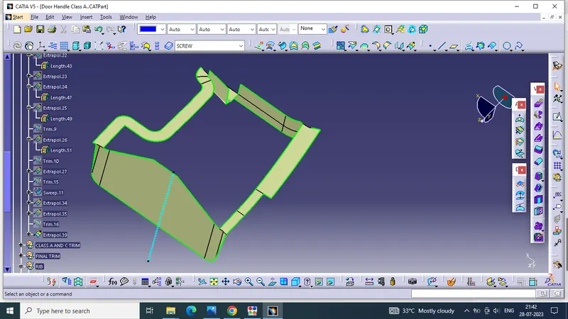
S.OLID SURFACE
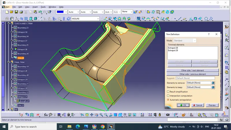
CLASS A and CLASS C is trim together
.
CLASS B is trimmed with CLASS A AND C
.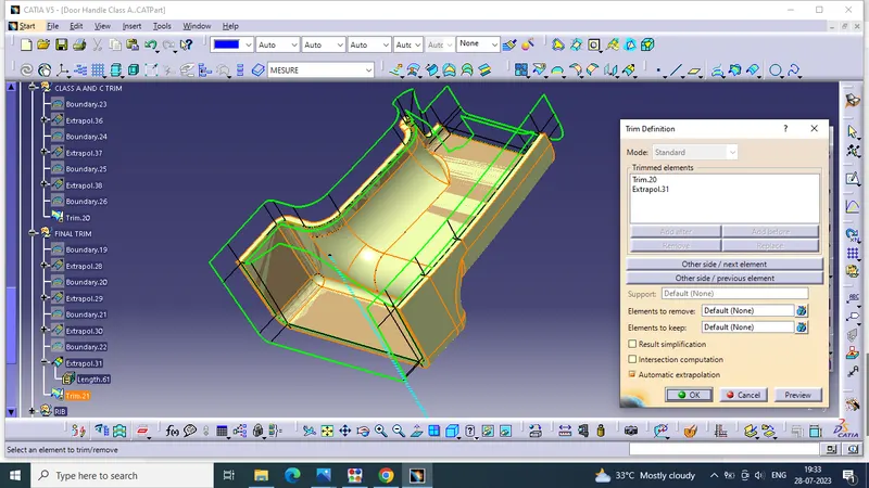
SOLID SURFACE FORMED
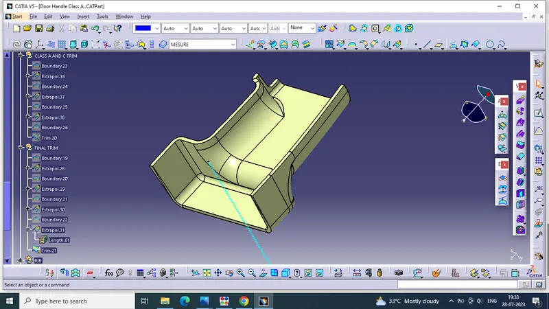
PART BODY
Close Surface feature usedto make a solid body from the surface
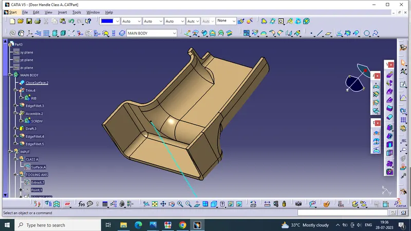
RIB DESIGN
.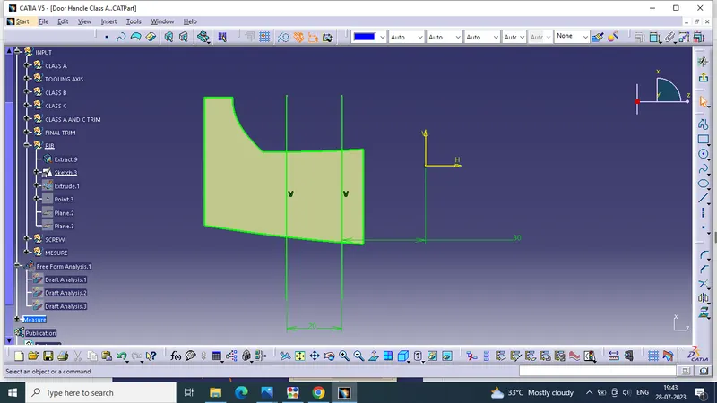
sketch is created for ribs
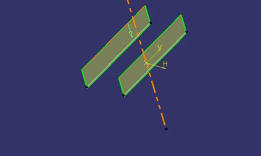
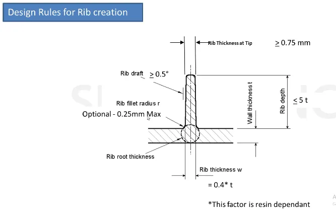
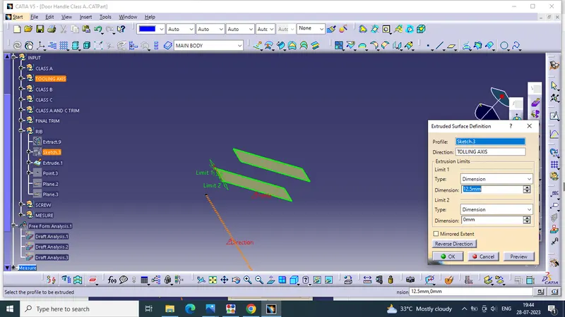
extruded and created the surface according to the height of ribs in design rules
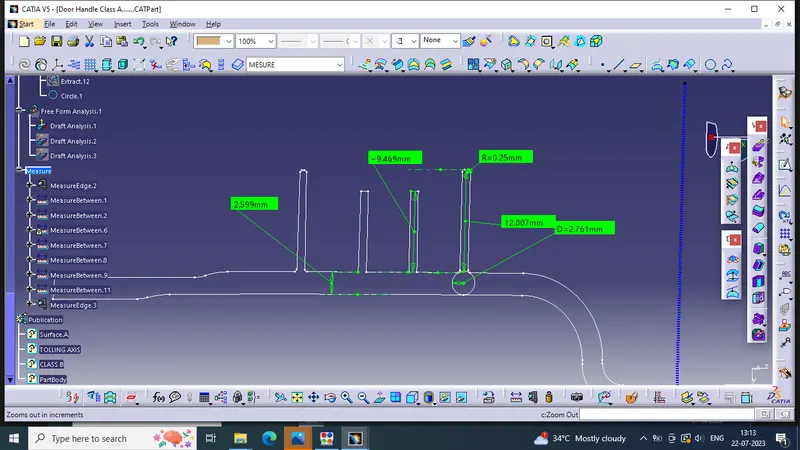
height - <=5t (thickness of part)
.
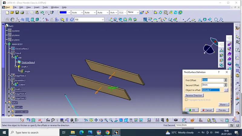
thicken the surface using thicken surface
thickness = 0.4t (thickness of part)
.
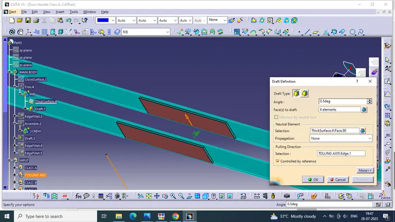
rib draft >= .5degree
.
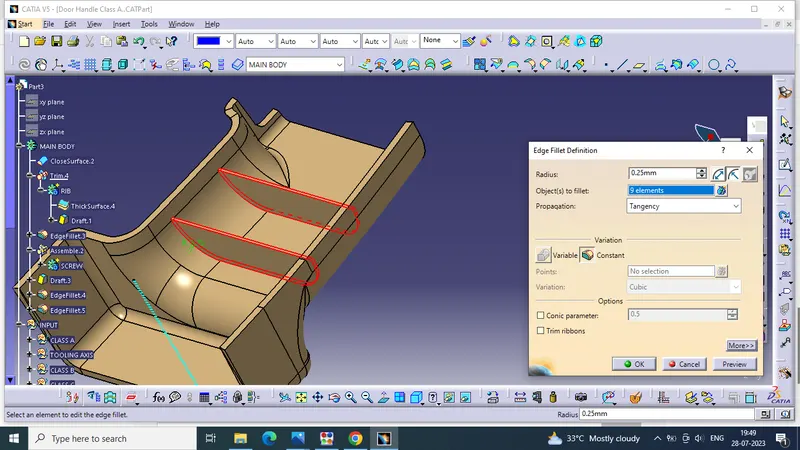
fillet .25mm
.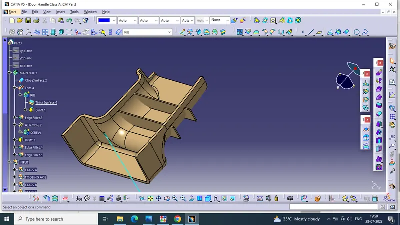
part is timmed with main component
SCREW BOSS
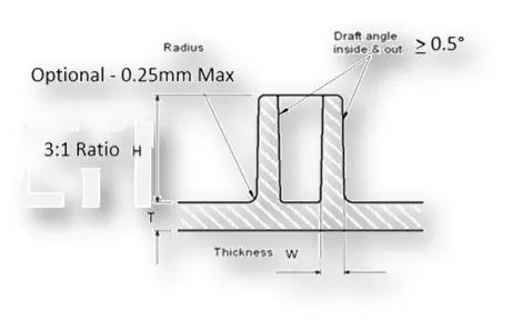
sketch is created the diameter taken (m6 bolt) 5.2mm
.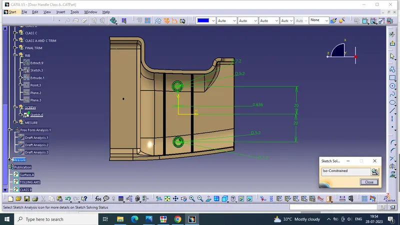
the outer diameter
Thickness - Typically 40%* of the nominal wall at the base in one side
40% of 2.5 =1 mm one side =7.2
.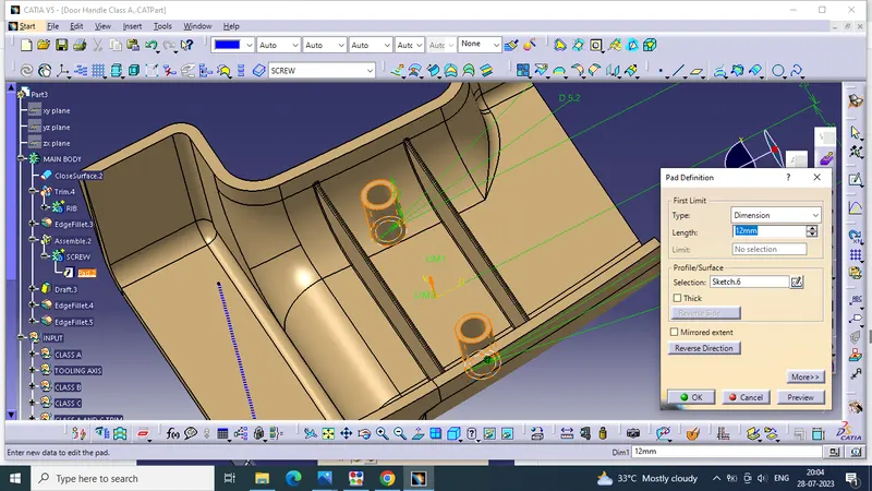
paded the sketch for height
Height to Diameter Ratio - 3
Draft - 0.5 degrees on the walls of boss
.
Radii - 0.25mm maximum radii.
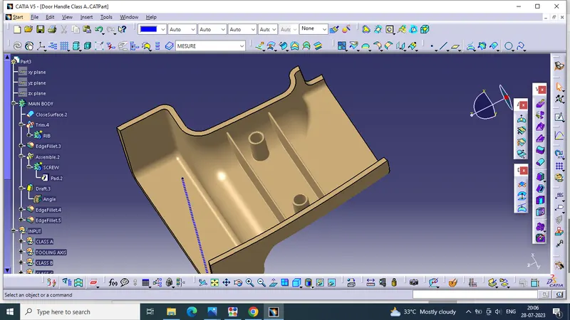
COMPONENT
.
DRAFT ANALYSISOF COMPONEN
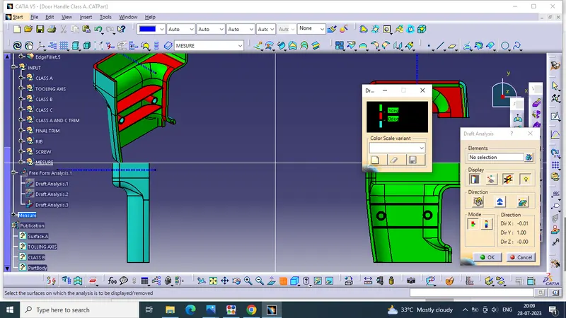
draft analysis is done using featured draft analysis tool
Use the compass fucnction to aling the compass to the tooling direction and lock the direction using lock function in the draft analysis tool bar
the surface is showing green colour so that the surface clears the minimum draft angle of 3 degree
By using the analyses under the running pointwe can check draft angle on the individual faces. It shows how much draft on specific points when we move the cursor point.
.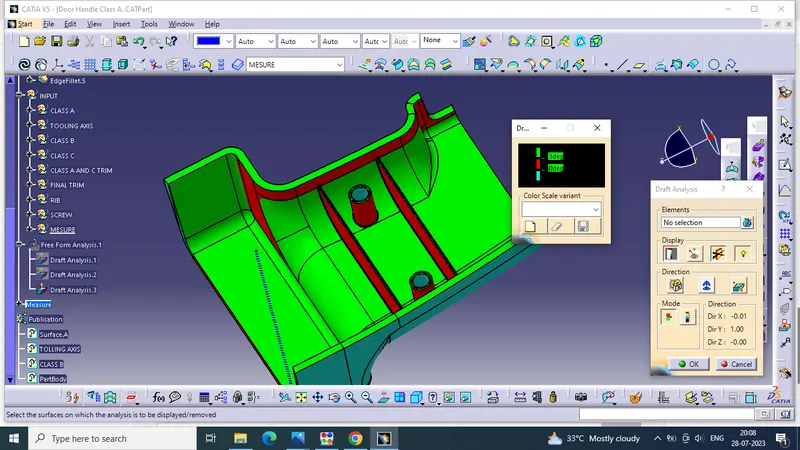
Green colour - above 3 degree positive draft
Red colour -between 3 and 0
blue colour- below 0 degree
TREE STRUCTURE
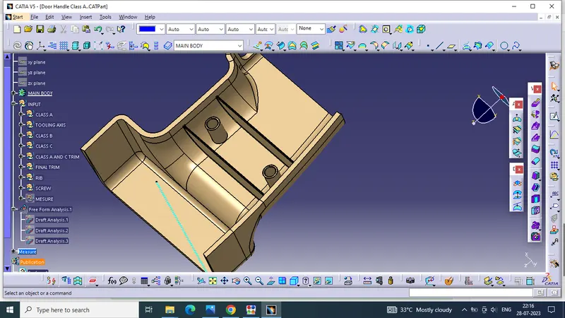
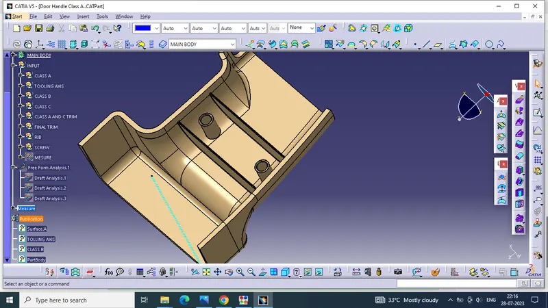
MESUREMENT FOR RIB AND SCREW
CONCLUSION
*TOOLING AXIS for the CLASS A SURFACE and MODEL is created
*CLASS B AND CLASS C surfaceis created from CLASS A surface
*SURFACE MODEL is created using CLASS A,B & C surface
*SOLID BODY is created from SURFACE MODEL using close surface
*RIBS AND SCREW BOSS are created considering the design rules
*DRAFT ANALYSIS is done on CLASS A SURFACE and SOLID BODY
*Publications: Use the publication option published the following.
Tooling Axis,Class A, B, and C surface & SURFACE MODEL,SOLID BODY