Week 10 - Challenge 1- Attachment Feature Creation (Ribs & Screw Boss)
AIM:
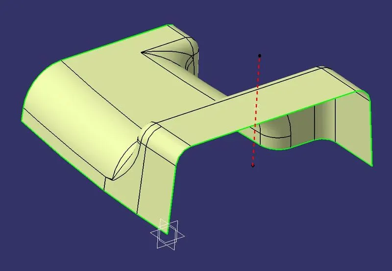
- To Create the Door Handle Component from the given Class-A surface.
- To Create the tooling axis for the given Class-A Surface meeting the requirements of the draft angle.
- To Attach B side Features in the component.
- To perform the Draft analysis on the model.
CREATING TOOLING AXIS :- The Tooling Direction is basically the direction that the mold pulls a part. The mold is built in two separate pieces, basically. You have a Cavity side and you have the Core side. The Core pulls apart from the Cavity and that's the Die line or the Tooling Direction.
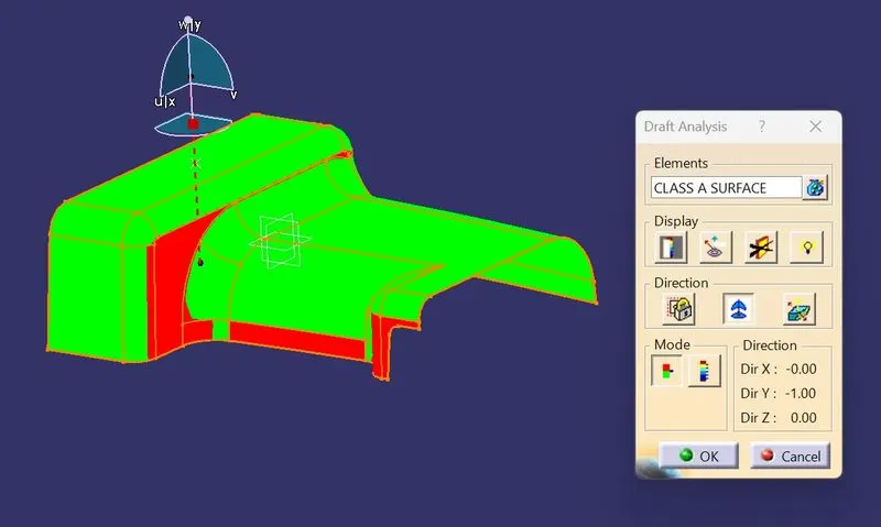
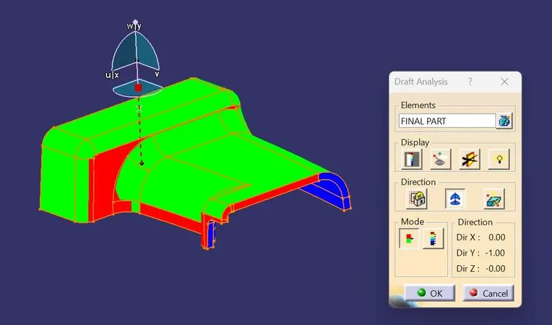
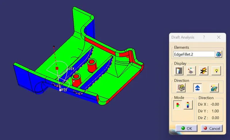
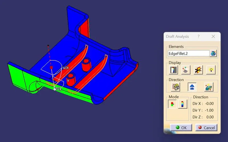
DRAFT ANALYSIS :- The Draft analysis command enables you to detect if the part you drafted will be easily removed. This type of analysis is performed based on color ranges identifying zones on the analyzed element where the deviation from the draft direction at any point, corresponds to specified values.
- Before going to drat analysis go to customized view parameter >under mesh >check material and then click ok.
- Now for draft analyses go to insert » analysis » feature draft analysis.
- Use the compasss to define the draft direction.
- In the colour scale change the draft angle to 3 degree.
- The component changes to green in indication of passing draft angle.
- Use running point to check the angle on the component.
PUBLICATION
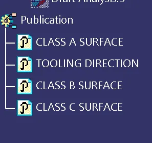
- Publication is done to the component to make it visible and navigate easily.
- To publish the component go to tools > publications and then select the tooling axis and the class A surface.
- A separate tree structure is formed under the main part.
CREATING CLASS B SURFACE :-
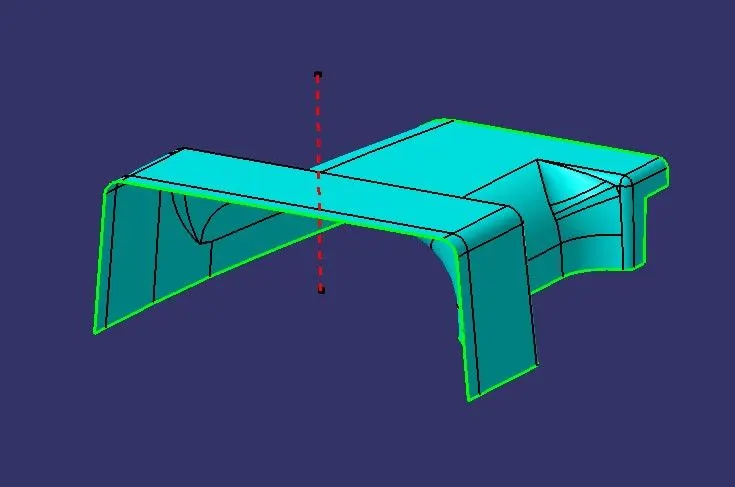
- Offset the class A surface by 3 mm.
- Use multi section surface command for fill the blank surface.
- Creat boundary for all the surface and extrapolate 2 mm.
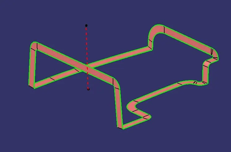
CREATING CLASS C SURFACE :- Class C surface creat by boundary and sweep command with the help of class A surface. Finally joined all the sweep to make class C surface.
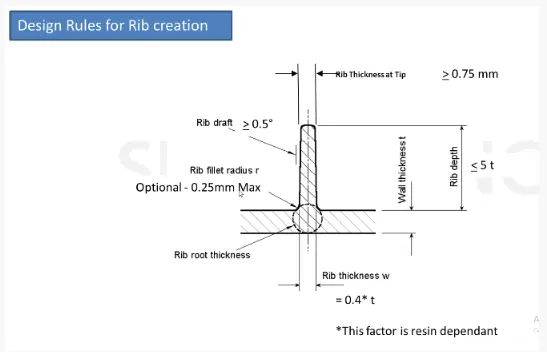
DESIGN PRINCIPLE FOR RIB CREATION :-
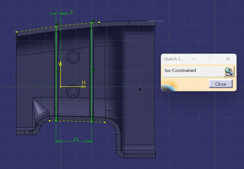
ISO CONSTRAINES SKETCH FOR RIB :-
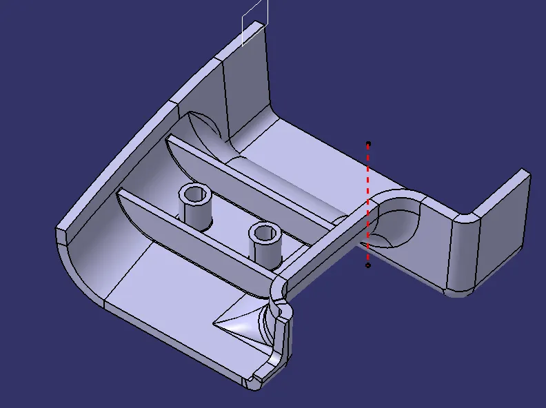
RIBS :- Ribs are thin wall protrusions that extend perpendicularly from a wall or plane. They are usually found in clusters offering support to a plane that would have otherwise been too thick, but can also be stand-alone support for a single wall. They are commonly used to provide additional support and strength to a part. Thickness and location are essential to rib design.
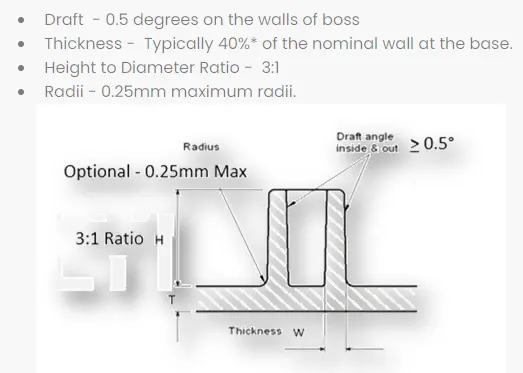
DESIGN PRINCIPLE FOR SCREW BOSS CREATION :-
ISO CONSTRAINES SKETCH FOR SCREW BOSS :-
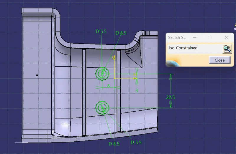
SCREW BOSS :- Screw Boss features are commonly found in injection molding designs. They are used to aid in the assembly of molded parts by providing a channel for a screw. Their primary use is to strengthen holes or slots in the surface present in the part model.
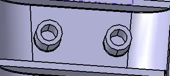
3D MODELS DIFFRENT VIEW :-
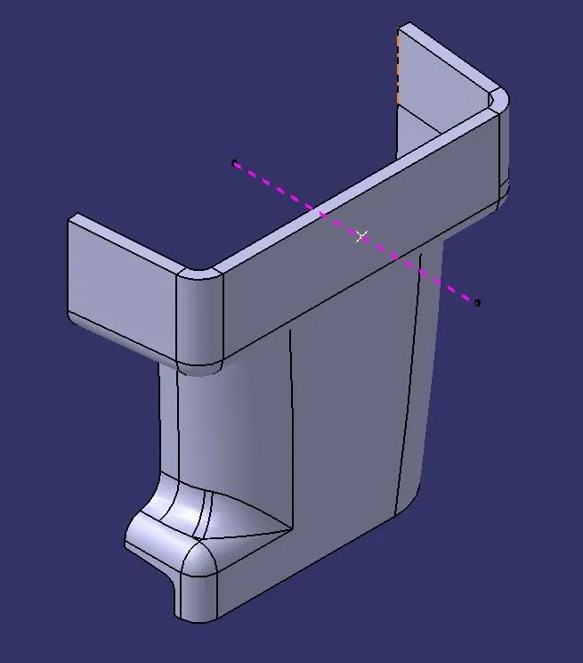
ISOMETRIC VIEW :-
FRONT VIEW :-
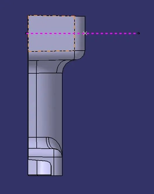
SIDE VIEW :-
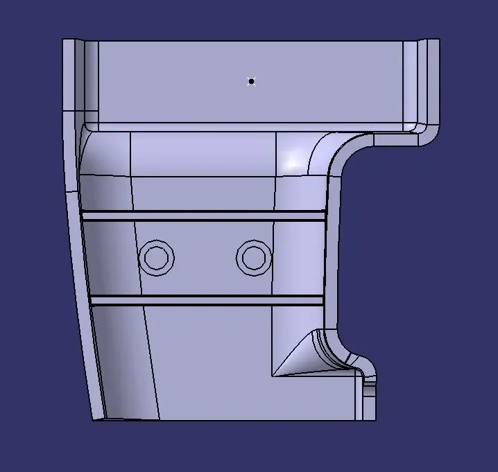
TOP VIEW :-
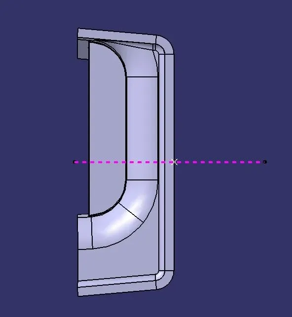
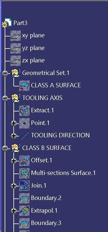
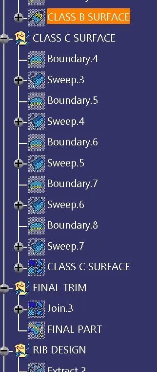
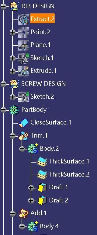
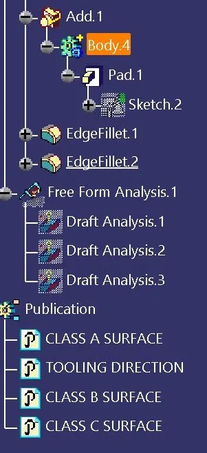
TREE STRUCTURE :-