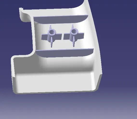
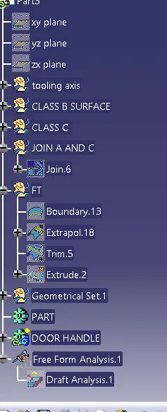
Week 10 - Challenge 1- Attachment Feature Creation (Ribs & Screw Boss)
1)
First we need to creat real tooling axis, for that we have to intersect the surface A in x and y axis then we got two dummy axis then we have to bisect the two lines in order to get the real tooling axis of surface .
1st we extract the bottom base because we can easily creat the tooling axis in z direction , then creat point on base surface and go for position sketch and select zx and zy plane for creating the dummy aixis
but in this complex model its very difficulty to vislble all parts in one axis. here we choose x axis because we can able to see more parts compare to other axis.
here, we set one point on appropriate edge for creating the tooling axis and creat line .
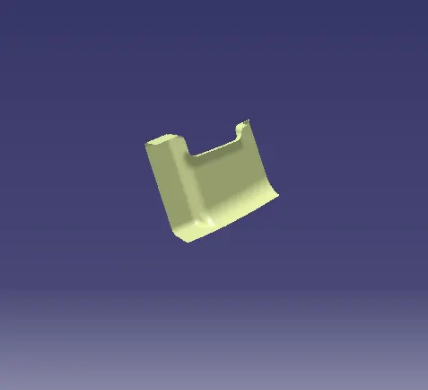
class b surface
offset the surface into2.5mm towords to inside and extract the non connectivity parts from main body
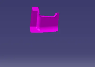
creat of class c surface
surface which has perpendicular to drafting axis then we have to go for drafting with tooling axis and gives 3 degree draft towards to outside
suppose surface which has parrallel to drafting axis then we go for reference with surface option and gives 90 degree for sweeep.
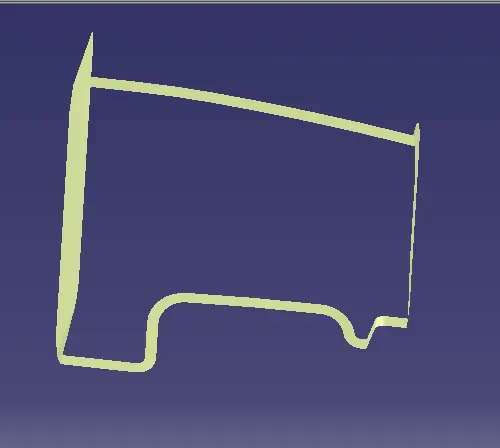
join A and C surface
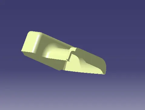
finally trim the class B with join A and C surface
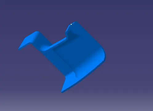
make it closed solid surface using closed surface
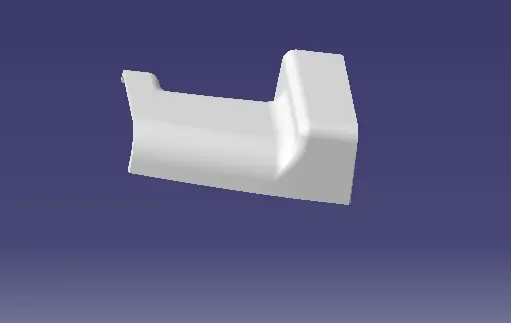
checking with drafting analysis
ensure the model should be 3 degree
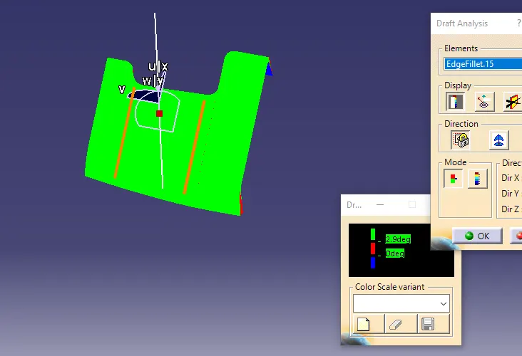
then creat srewboss and ribs on surface B
CREAT SKETCH FOR SREWBOSS
here, I used the M6 bolt and nut, hole dia is 5.2 , we should follow the 0.6*t formula for calculating outer dia of scew boss and height should be t*5times
edge fillet sholud be 0.25m
draft shold be 0.5m
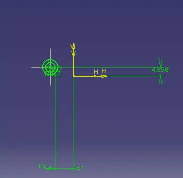
PAD THE BOSS
CREAT THE RIBS
Ribs thickness should be 0.4*t using this formula for calculating the thickness
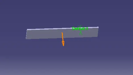
FINALLY ASSEMBLE TO THE MAIN BODY