Week 10- Assembly Workbench
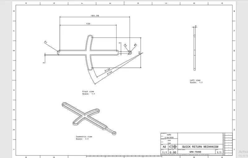
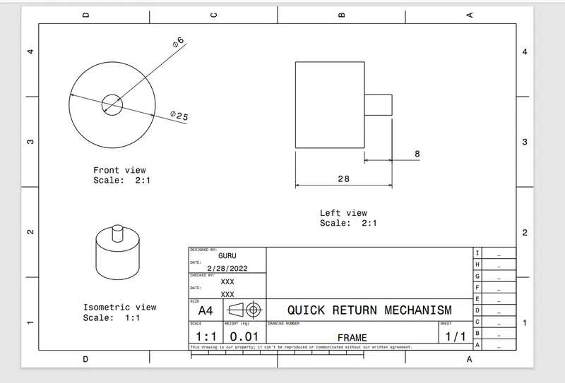
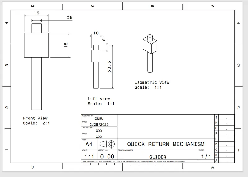
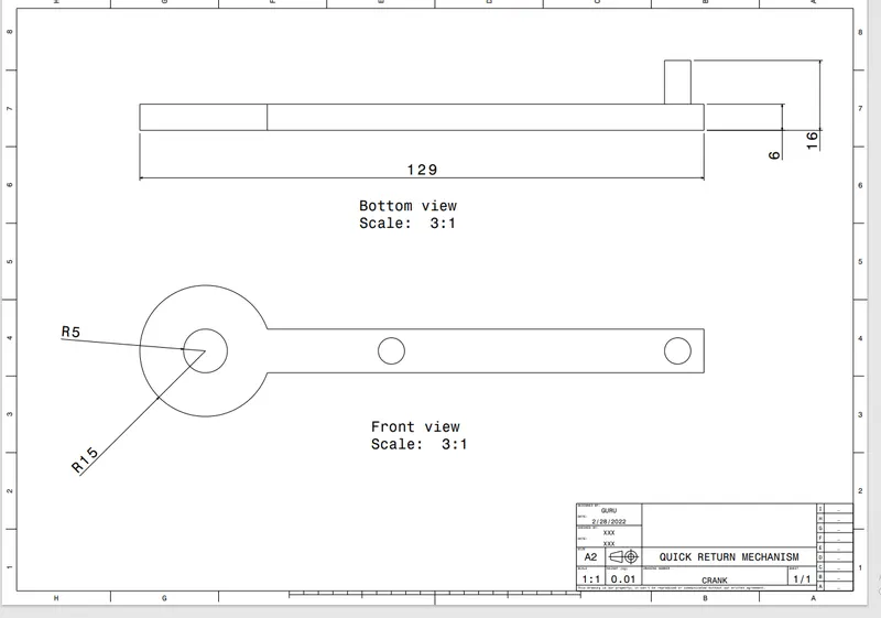
According to the input datas they have given , we must devolop the 2d drawings into 3d solid models .
Model drawing 1 shows the quick return mechanism components ,
QUICK RETURN MECHANISM
A quick return mechanism is an apparatus to produce a reciprocating motion in which the time taken for travel in return stroke is less than in the forward stroke. It is driven by a circular motion source (typically a motor of some sort) and uses a system of links with three turning pairs and a sliding pair.
A quick return motion mechanism is used in the shaper and slotter machine in which the circular motion is converted into reciprocating motion so that the slider moves forward and backwards. In the forward direction, the cutting process occurs while in return there is no such cutting.
PROCEDURE FOLLOWED WHILE WORKING ON THIS PROJECT :
this mechanism has 5 parts and they are
1 quick return mechanism frame
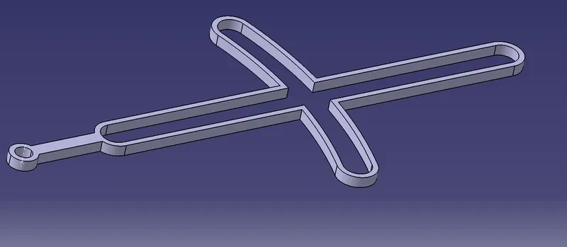
2 frame holder
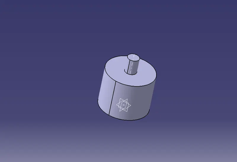
3 slider
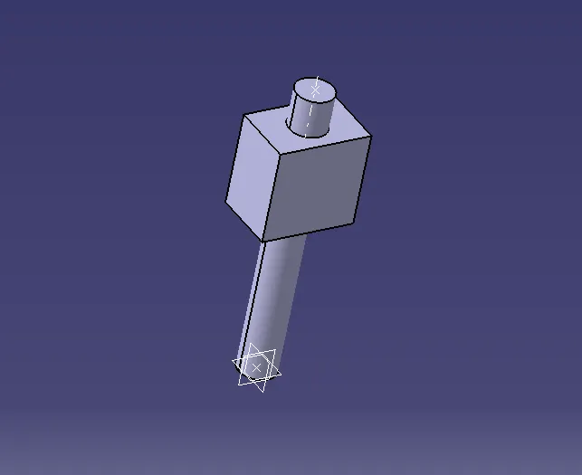
4 crank
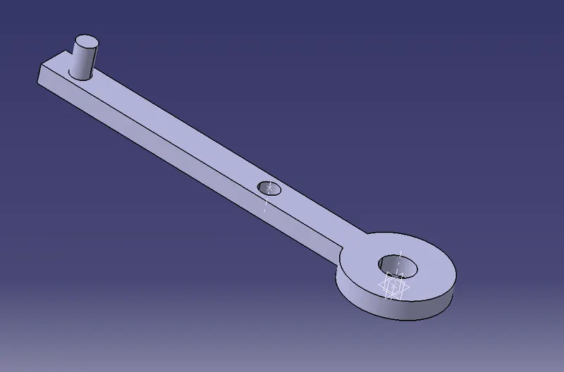
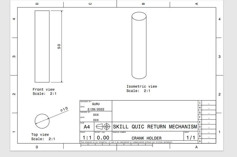
crank holder
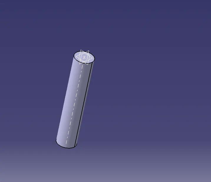
Procedure for devoloping the part
first we sketch the quick return mechanism mechanism frame in sketcher workbench and then the sketch is devoloped in solid by padding the sketch to the given value
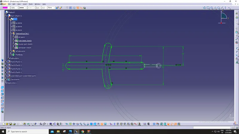
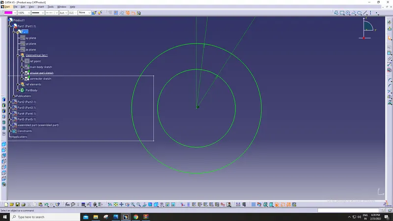
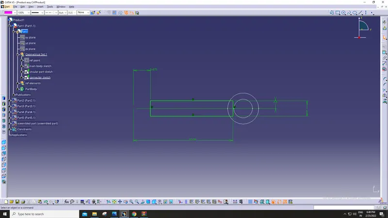
and the solid parts finally undergo boolean operations to get into desired part .
The similar procedure is done for the other parts too
Frame holder
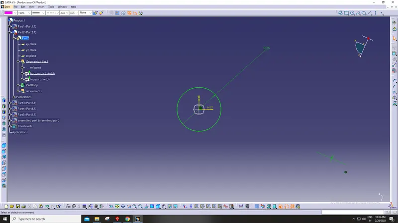
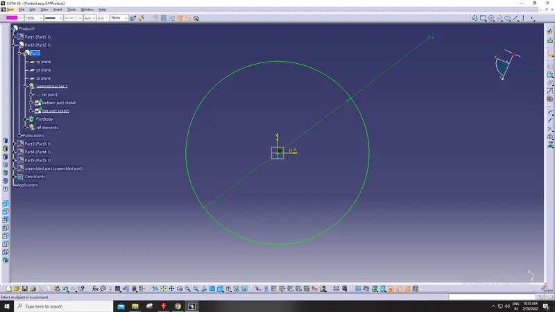
Slider
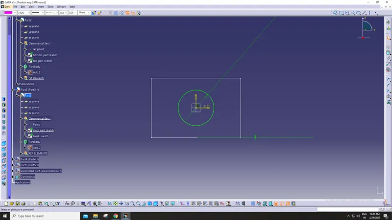
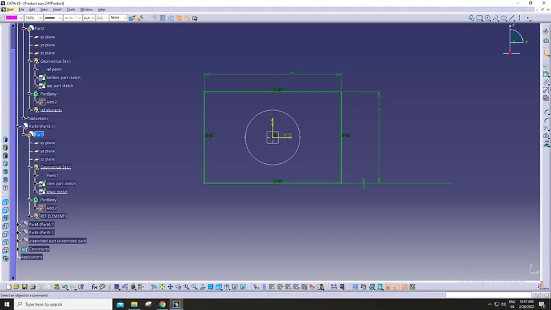
Crank
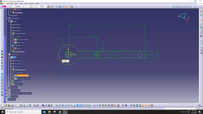
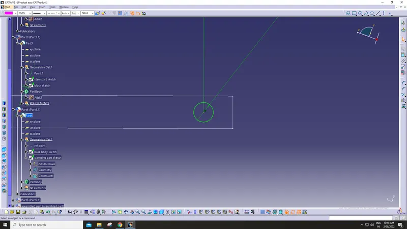
Crank holder
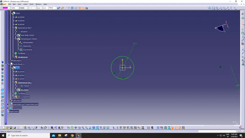
Procedure for assembling the parts
From here we jump into the product workbench , in that insert all the designed parts using insert existing components tool
And then insert a new part and make it as a reference part , this is the empty part in which all the parts are going to get assembled
Then using constraint tools , assemble them to their desired Position and then lock them in accordance with their position and movements
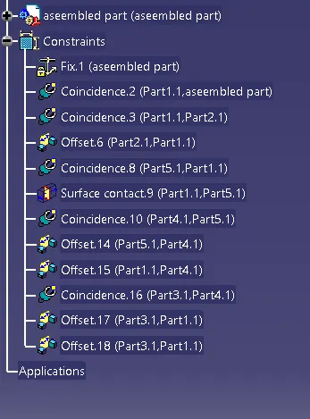
these are the constraints used to assemble the parts
Model drawing 2 shows the quick return mechanism components ,
CV JOINT
PROCEDURE FOLLOWED WHILE WORKING ON THIS PROJECT :
this mechanism has 3 parts and they are
1 conjuction part
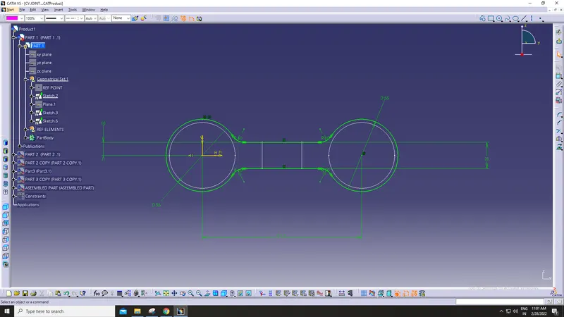
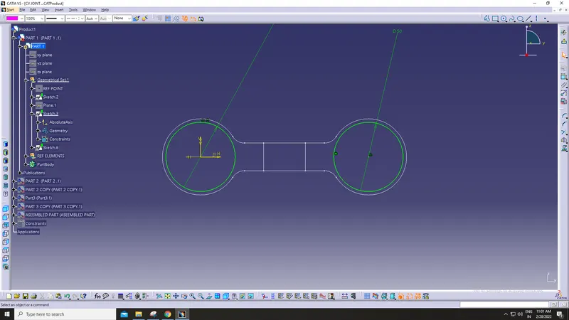
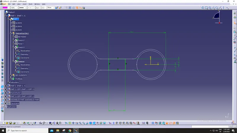
2 circular converging point
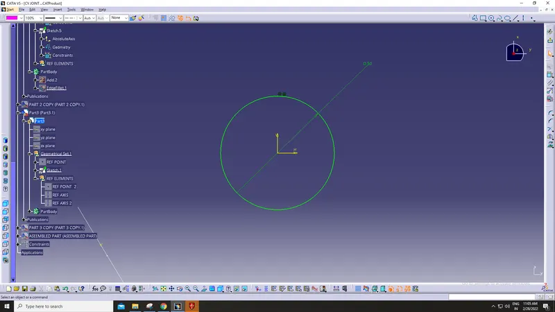
3 vertical movement part or type c part
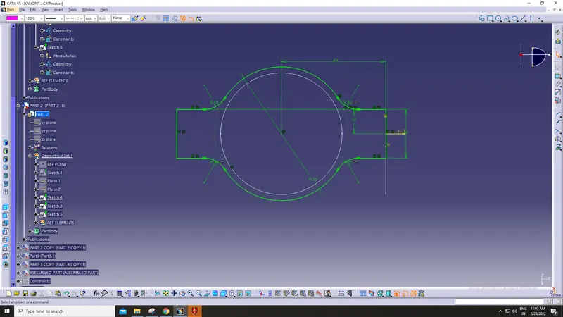
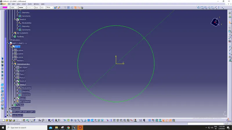
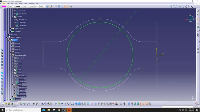
Procedure for assembling the parts
From here we jump into the product workbench , in that insert all the designed parts using insert existing components tool
And then insert a new part and make it as a reference part , this is the empty part in which all the parts are going to get assembled
Then using constraint tools , assemble them to their desired Position and then lock them in accordance with their position and movements
these are the constraints used to assemble the parts
SCREENSHOTS of drafting for the parts and assembly as given in MODEL 1
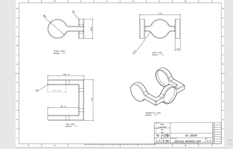
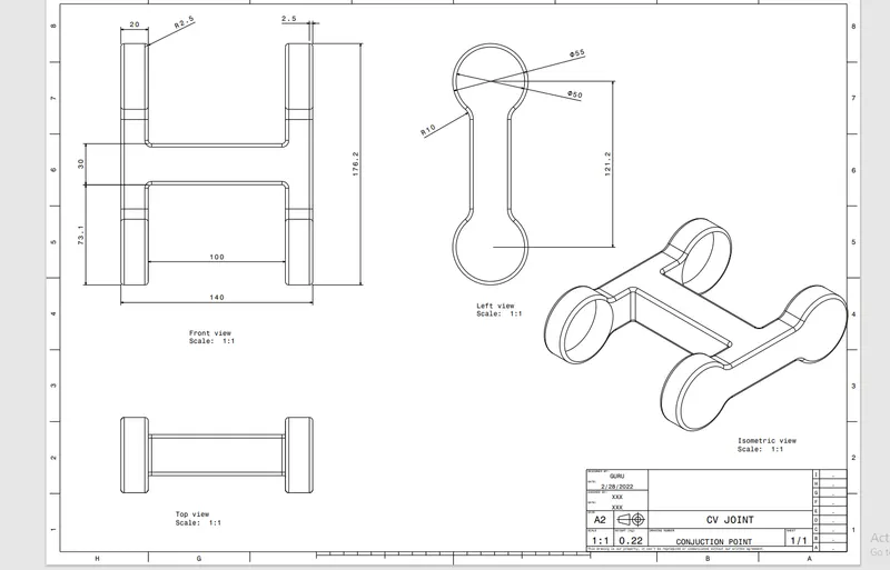
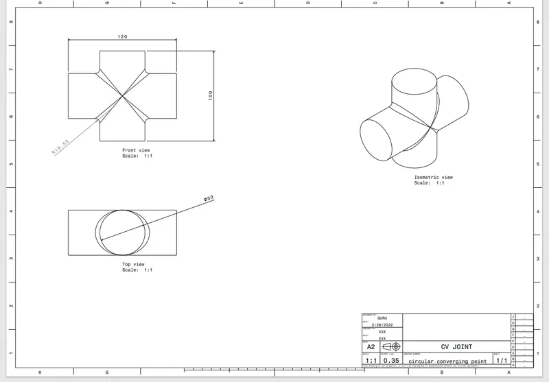
SCREENSHOTS of drafting for the parts and assembly as given in MODEL 2