Week 10- Assembly Workbench
- AIM :
To create 2 assemblies according to the content provided with 2D diagrams of the components by first creating the individual part files and then create a complete assembly of those part files in the assembly workbench. After creating the assembly make use of the drafting tools to create a 2D drawing similar to the assembly parts.
- THEORY :
Assembly modeling is the process of creating designs that consist of two or more components assembled together at their respective work positions. The components are brought together and assembled in Assembly Design workbench by applying suitable parametric assembly constraints to them. The assembly constraints allow you to restrict the degrees of freedom of components on their respective work positions.
- ASSEMBLY WORKBENCH :
The assembly files in CATIA are called Product files. There are two methods to invoke the Assembly Design workbench of CATIA. The primary method to start a new product file is by selecting File > New from the menu bar to open the New dialog box From this dialog box select Product. The other method of invoking the Assembly Design workbench is by choosing Start > Mechanical Design > Assembly Design from the menu bar.
- Types of Assembly Design Approach :
In CATIA you can create assembly models by adopting two types of approaches. The first design approach is the bottom-up approach, and the second one is the top-down approach.Both these design approaches are discussed below.
1.Bottom-up Assembly -
The bottom-up assembly is the most preferred approach for creating assembly models. In this of approach, the components are created in the Part Design workbench as (*.CATPart) file. Then the product (*.CATProduct) file is started and all the previously created components are inserted and placed in it using the tools provided in the Assembly Design workbench.
After inserting each component, constraints are applied to position them properly in the 3D space with respect to other components.
2.Top-down Assembly -
In the top-down assembly design approach, components are created inside the Assembly Design workbench. Therefore, there is no need to create separate part files of the components.
This design approach is completely different from the bottom-up design approach. Here you have to start the product file first and then, one by one, create all components. Note that even though the components are created inside the product file, they are saved as individual part files and can be opened separately later.
Note : An assembly can also be created by using the combination of both the top-down and bottom-up assembly design approaches.
How does a constant velocity joint work?
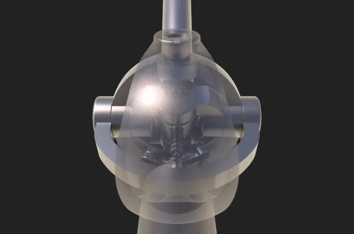
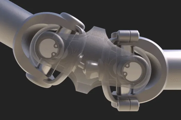
Constant velocity, or CV, joints are used to connect your vehicle’s transmission to your wheels. CV joints are part of the driveshaft and are used primarily on front-wheel drive vehicles, but they are also used in rear- and four-wheel drive vehicles. Each drive wheel has two CV joints: the inner joint connects the transmission to the axle, and the outer joint connects the axle to the wheel. The CV joint’s name comes from its ability to move with your vehicle’s suspension in any direction (if your vehicle hits a pothole or an uneven surface) and still be able to keep the drive wheels moving at a constant velocity. The CV joint is a very special joint: it connects two different rotating shafts. These two rotating shafts are stuck in a fixed position;
so, the CV joint must be able to move and bend to keep these two shafts connected. CV joints are being used in newer vehicles and are taking the place of the old “U” joints. The CV joint is able to transmit even levels of torque to the wheels continually no matter what angle it’ in. This means that no matter how many potholes you hit, or if the vehicle is turning, the CV joint will keep the drive wheels moving at a constant velocity.
- PROCEDURE :
STEP 1 - CREATING BOTTOM-UP ASSEMBLIES :
As mentioned earlier, while creating an assembly using the bottom-up approach, the components are created in separate part files and are then inserted into the assembly file. They are assembled at their working position by applying assembly constraints to them. To create an assembly using this approach, it is recommended to insert the first component and fix its position after properly orienting it in the 3D space. The other components can be inserted and positioned with reference to the first component. The method used for placing components inside the product file is discussed below.
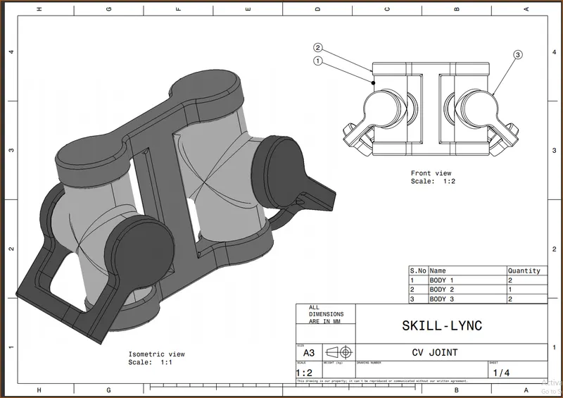
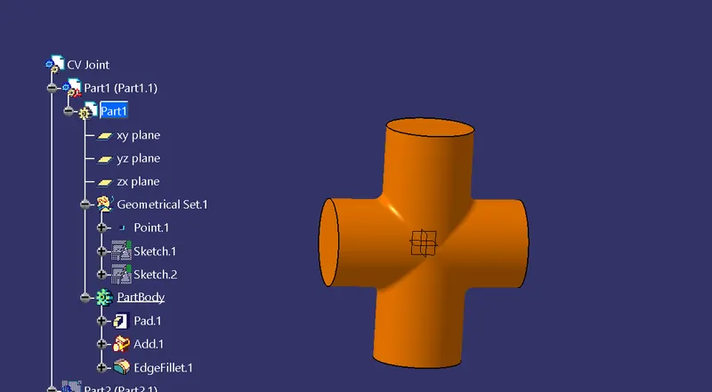
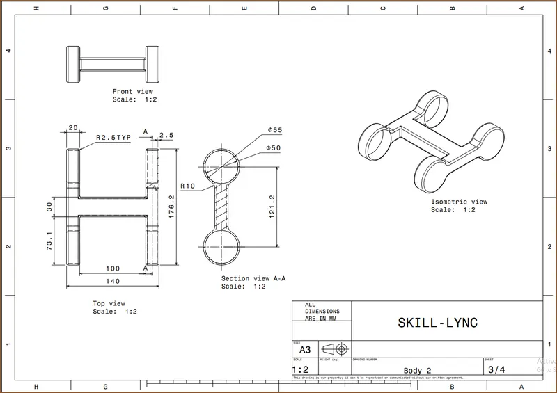
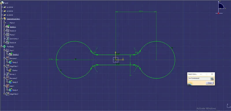
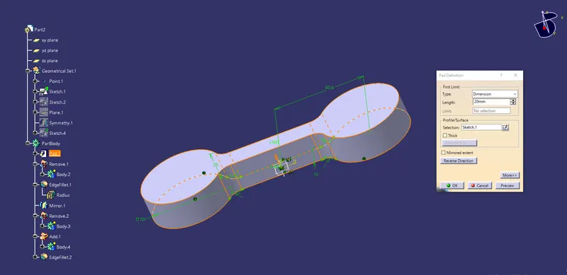
Now we will create a CV joint assembly which consists of 5 parts in which few parts are identical which we can duplicate/copy later
PART 1 :
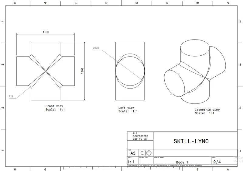
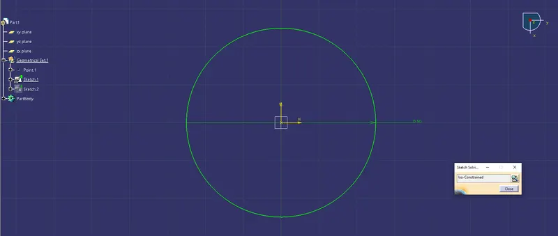
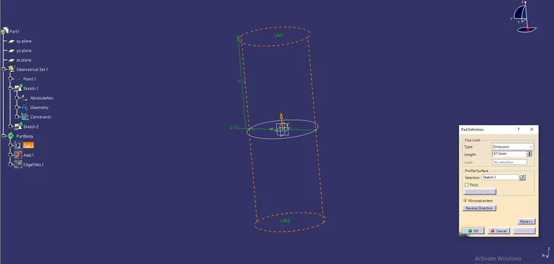
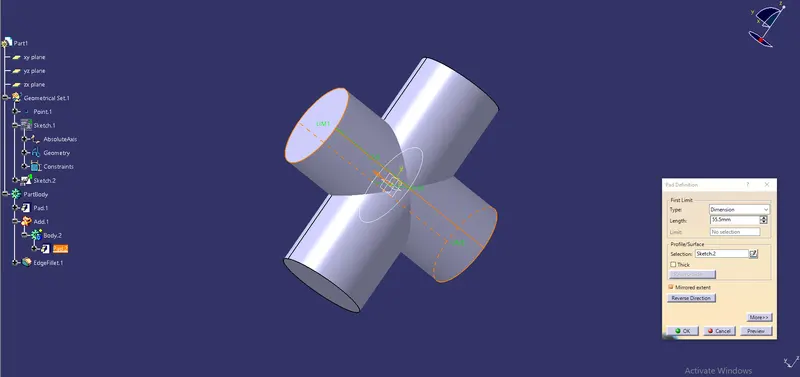
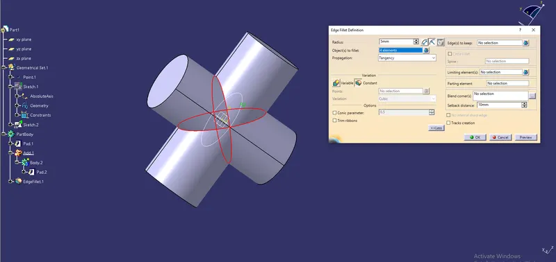
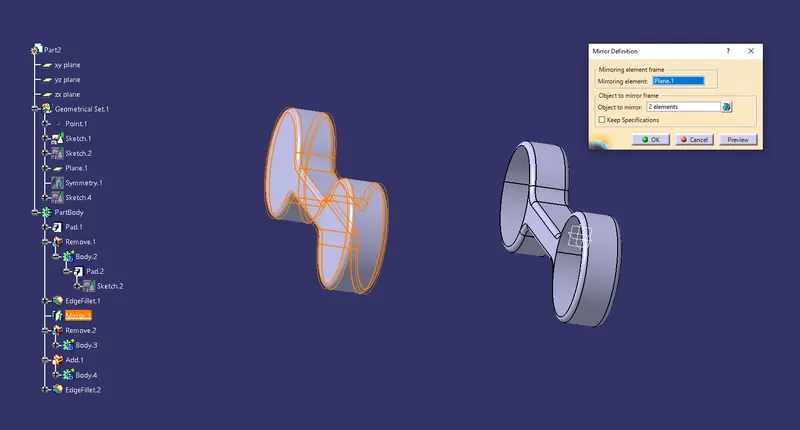
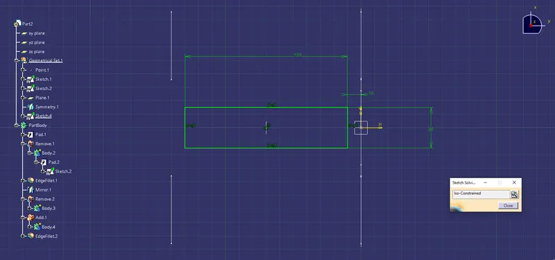
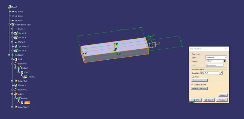
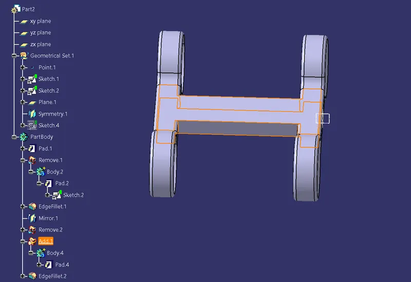
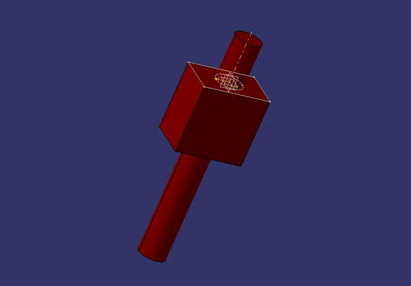
Desgining cross fitting part
PART 2 :
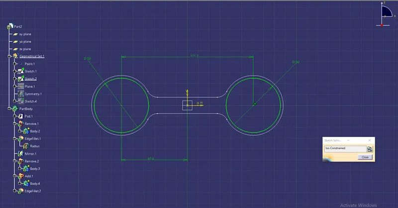
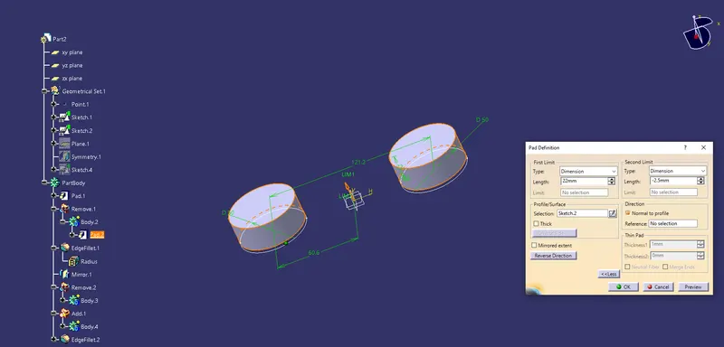
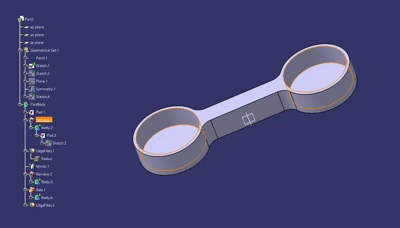
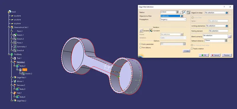
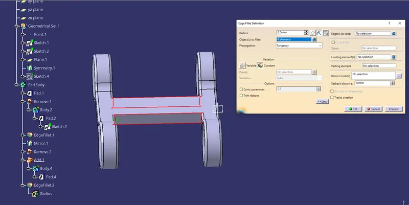
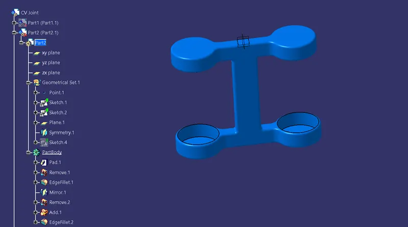
PART 3 :
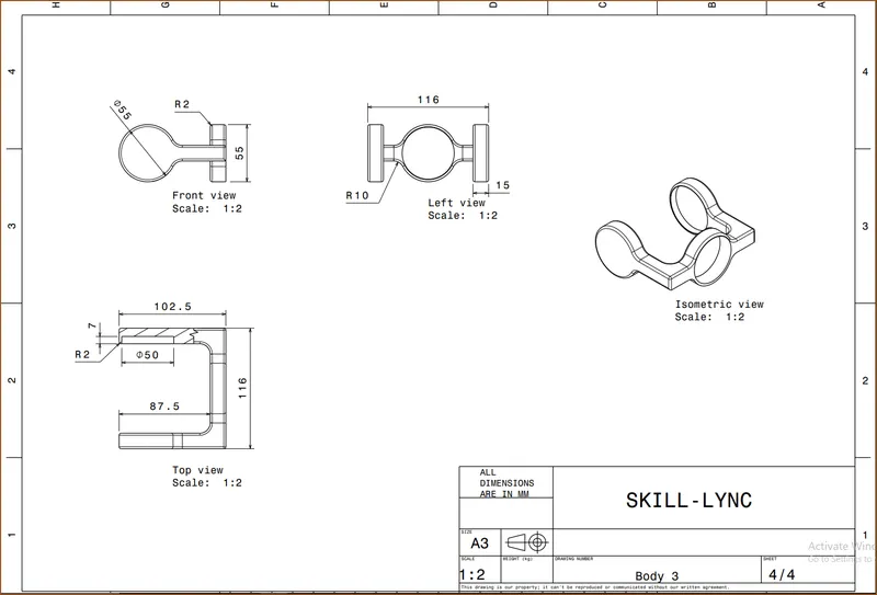
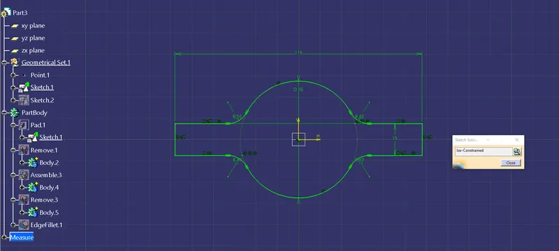
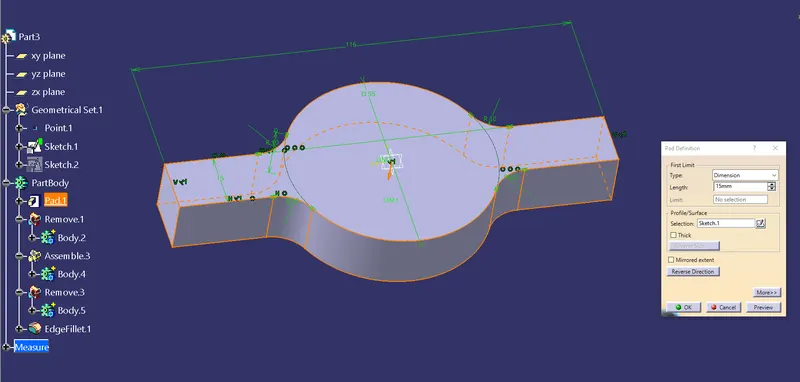
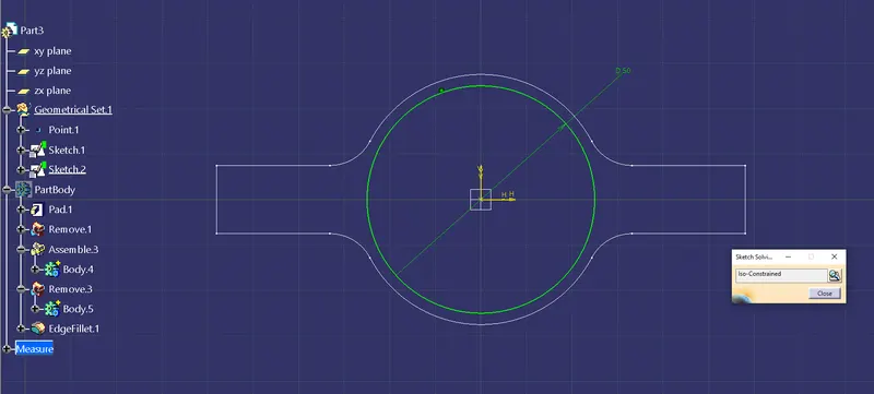
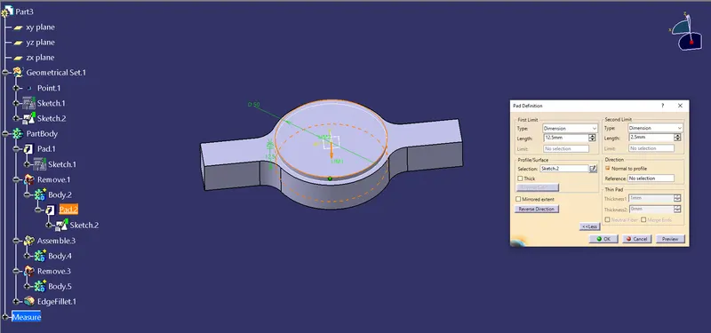
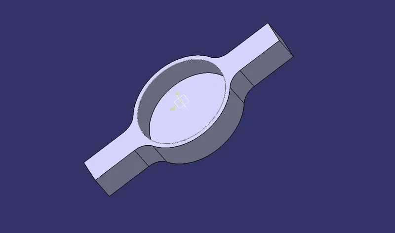
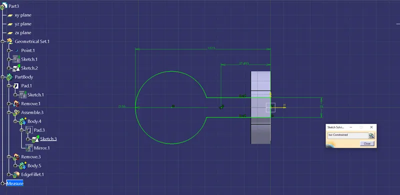
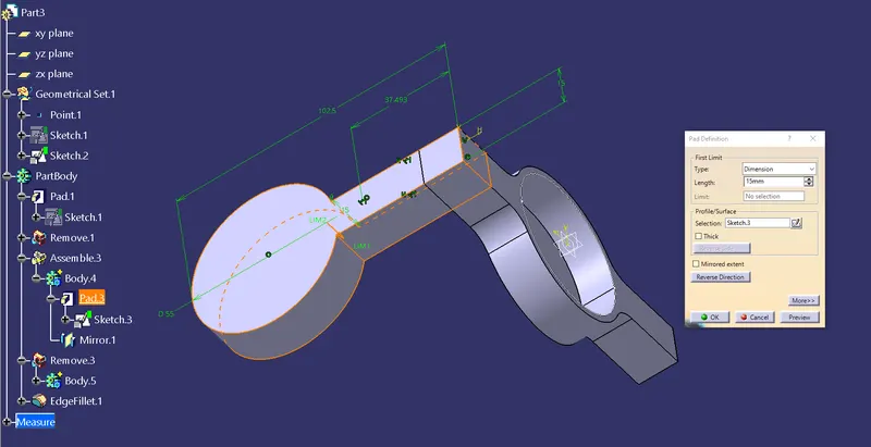
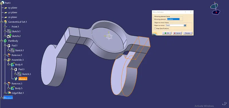
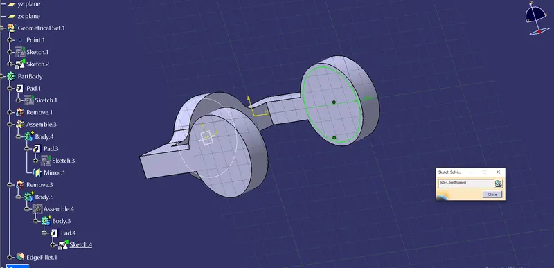
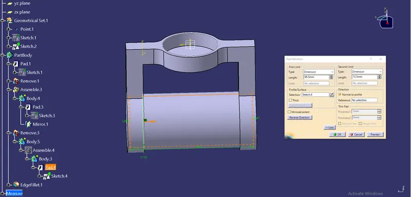
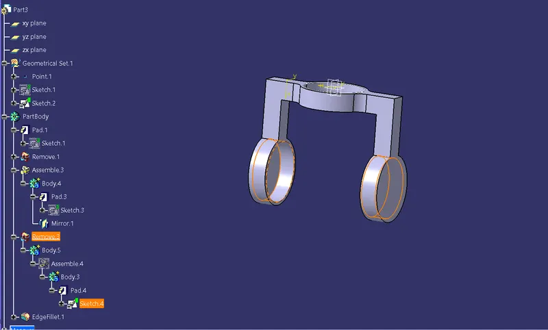
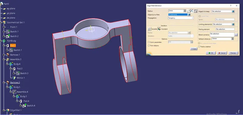
After placing the components in the product file, you need to assemble them. By assembling the components, you will constrain the degree of freedom of the components. As mentioned earlier, the components are assembled using the constraints. Constraints help you to precisely place and position the components with respect to the other components and the surroundings in the assembly. If all degrees of freedom of all components of the assembly are restricted, it is called a fully constrained assembly. Else it is called a partially constrained assembly. If some mechanism needs to be created after assembling the components, some degrees of freedom of the assembly needs to be kept free intentionally, so that movements can be achieved in that direction. Various types of constraints available in CATIA are discussed below.
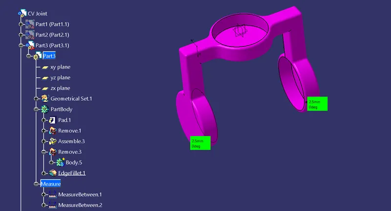
Contact Constraint :
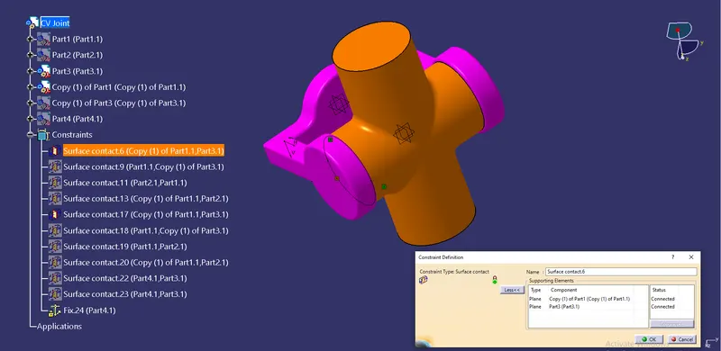
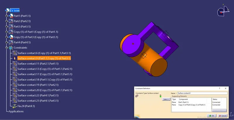
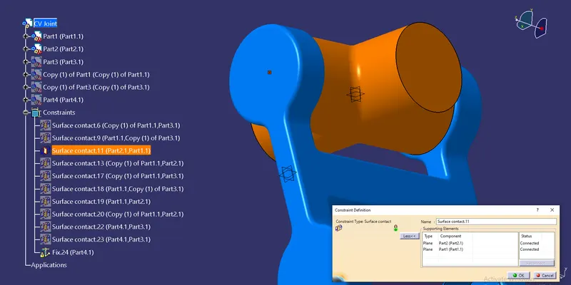
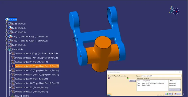
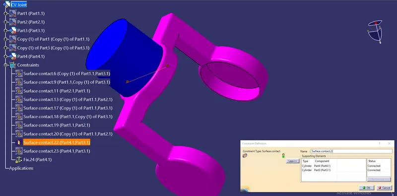
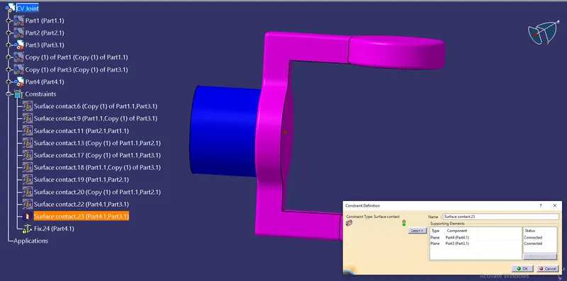
The Contact Constraint is applied to make a surface to surface contact between two selected elements from two different components. The elements to be selected can be planes, planar faces, cylindrical faces, spherical faces, conic faces, or circular edges. To invoke this tool, choose the Contact Constraint button from the Constraints toolbar.you are prompted to select the first geometric element of the Contact constraint. Select the element from the first component. Next, you are prompted to select the geometric element to place in contact with the first selection. Select the element from the second component. A Contact constraint will be applied between the two elements and the component will be placed with respect to the constraints after updating. The Contact constraint symbol will be displayed on the assembled components.
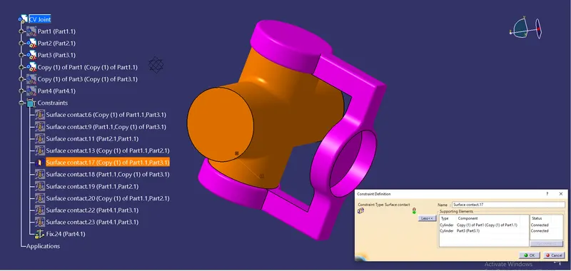
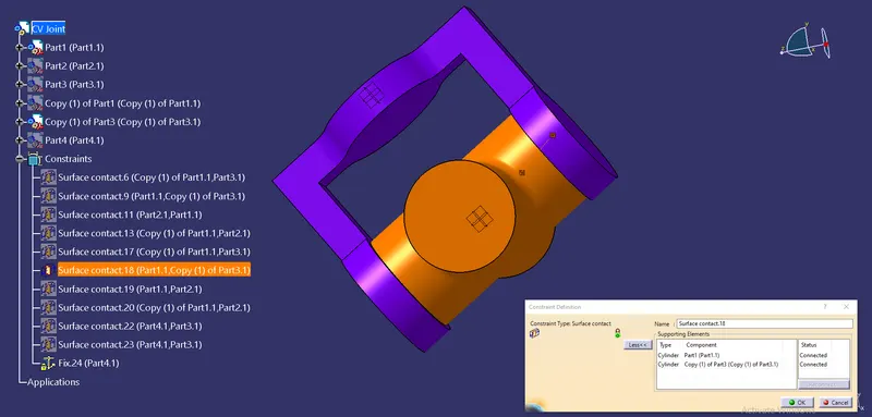
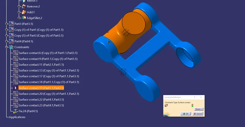
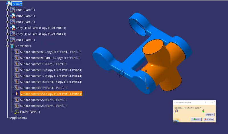
Fix Together :
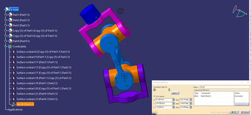
The Fix Together constraint is used to fix the position of the selected components with respect to each other. Once the selected components are fixed together, they can be moved as a single component such that the position of one component with respect to another component remains the same. To invoke this tool, choose the Fix Together button from the Constraints toolbar; the Fix Together dialog box is displayed. Now, select components to be linked. The part number of the selected components are displayed in the Fix Together dialog box.If you want to remove a particular component from the list, click on its part number in the Components selection area. Choose the OK button from the Fix Together dialog box to apply the Fix Together constraint.
Moving and Rotating Using the Manipulation Tool
The Manipulation tool is used to move or rotate the component freely by dragging
the cursor. To translate or rotate any component, choose the Manipulation button
from the Move toolbar.
After assembling all the components the video shows how the cv joint is suppposed to move based on the contact contrains we have given.
ASSEMBLY 2 : QUICK RETURN MECHANISM
Quick return mechanism -
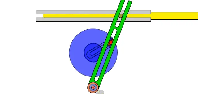
A quick return mechanism is an apparatus that consists of a system of links with 3 turning pairs and a sliding pair that can convert rotary motion into reciprocating motion. The time taken for travel in return stroke is less than in forward stroke.A quick return mechanism is also known as Crank and slotted lever quick return motion mechanism.
It consists of 3 turning pairs and one sliding pair as shown below.
CREATING BOTTOM-UP ASSEMBLIES :
As mentioned earlier, while creating an assembly using the bottom-up approach, the components are created in separate part files and are then inserted into the assembly file. They are assembled at their working position by applying assembly constraints to them. To create an assembly using this approach, it is recommended to insert the first component and fix its position after properly orienting it in the 3D space. The other components can be inserted and positioned with reference to the first component. The method used for placing components inside the product file is discussed below.
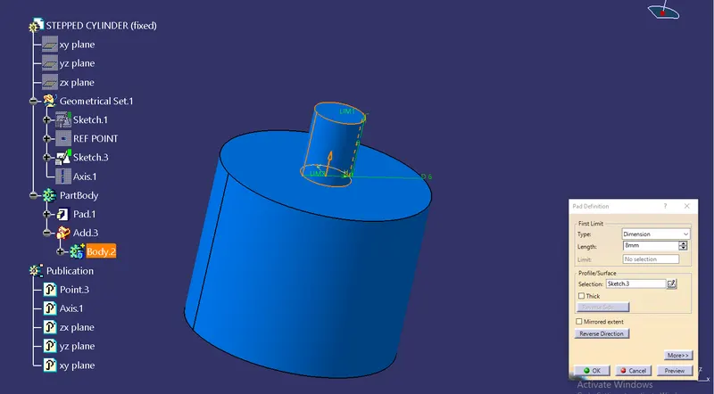
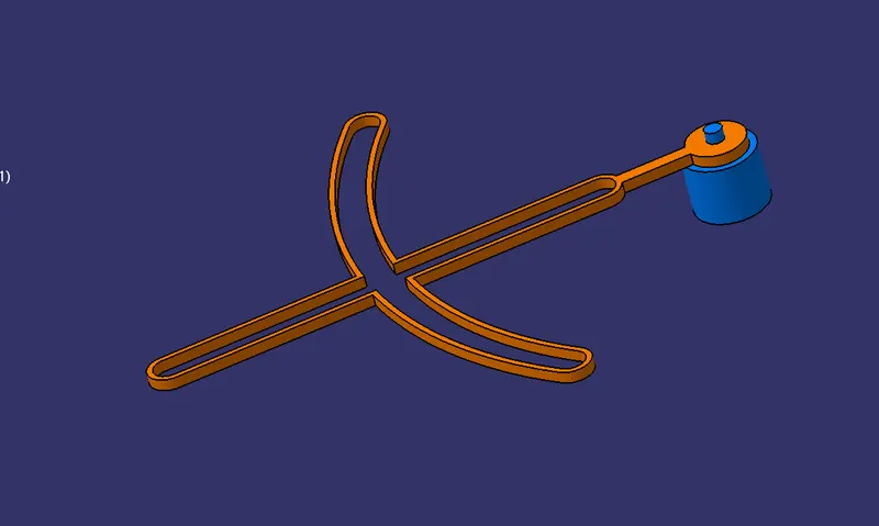
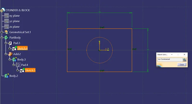
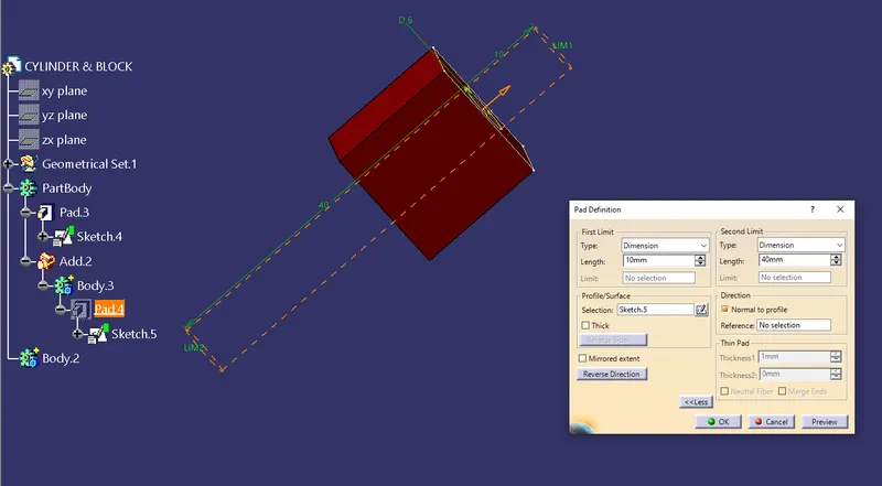
Now we will create a QRM assembly which consists of 5 parts seperately in part workbench and assemble them later :
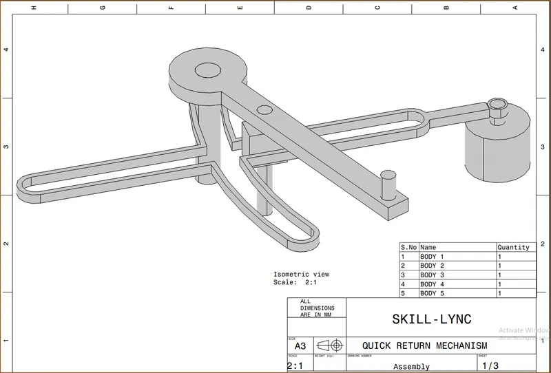
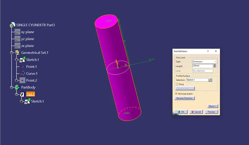
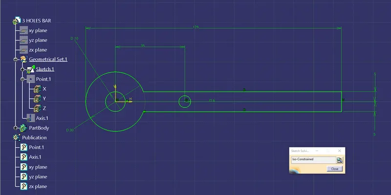
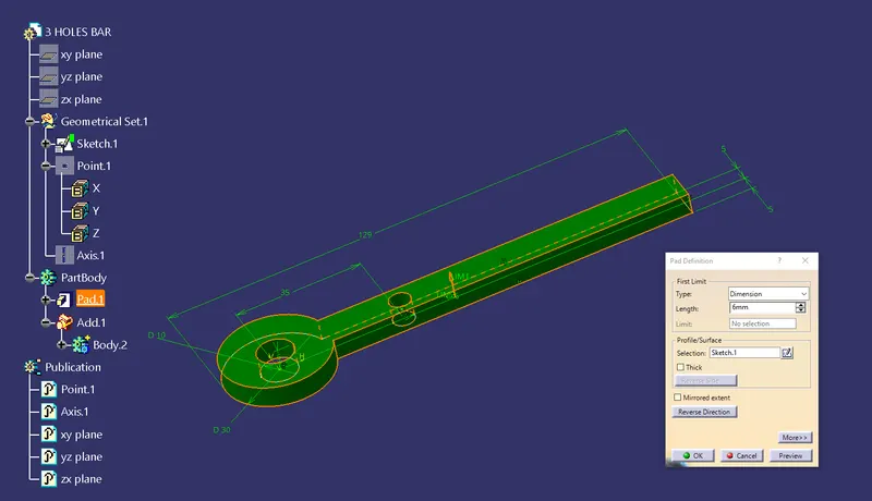
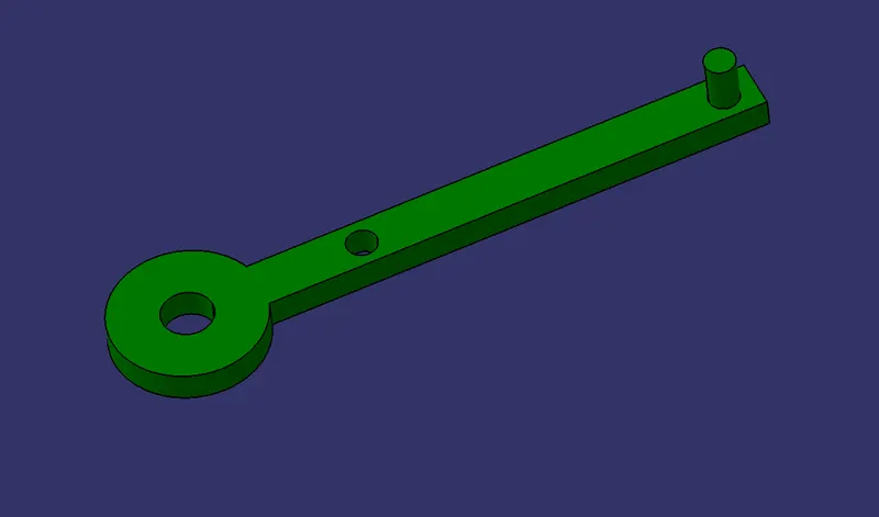
PART 1 :
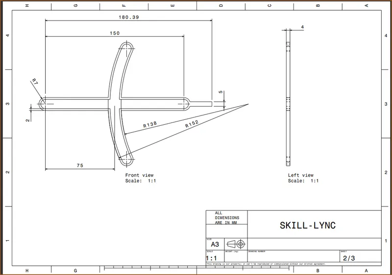
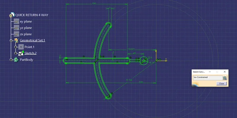
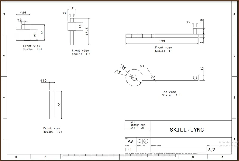
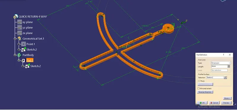
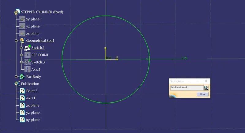
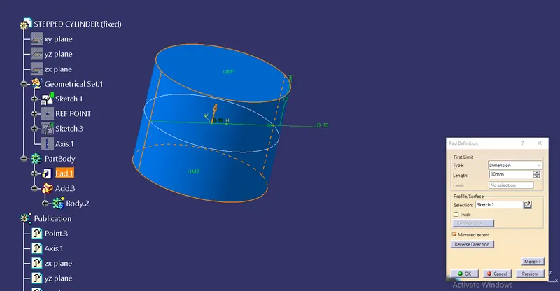
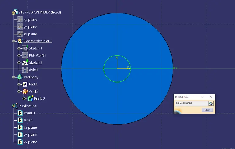
After placing the components in the product file, you need to assemble them. By assembling the components, you will constrain the degree of freedom of the components. As mentioned earlier, the components are assembled using the constraints. Constraints help you to precisely place and position the components with respect to the other components and the surroundings in the assembly. If all degrees of freedom of all components of the assembly are restricted, it is called a fully constrained assembly. Else it is called a partially constrained assembly. If some mechanism needs to be created after assembling the components, some degrees of freedom of the assembly needs to be kept free intentionally, so that movements can be achieved in that direction. Various types of constraints available in CATIA are discussed below.
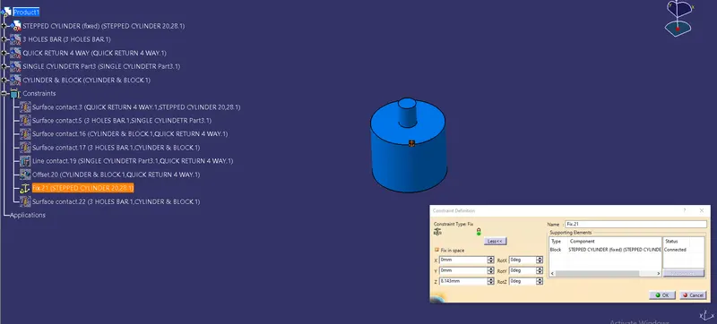
Contact Constraint :
The Contact Constraint is applied to make a surface to surface contact between two selected elements from two different components. The elements to be selected can be planes, planar faces, cylindrical faces, spherical faces, conic faces, or circular edges. To invoke this tool, choose the Contact Constraint button from the Constraints toolbar.you are prompted to select the first geometric element of the Contact constraint. Select the element from the first component. Next, you are prompted to select the geometric element to place in contact with the first selection. Select the element from the second component. A Contact constraint will be applied between the two elements and the component will be placed with respect to the constraints after updating. The Contact constraint symbol will be displayed on the assembled components.
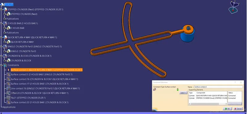
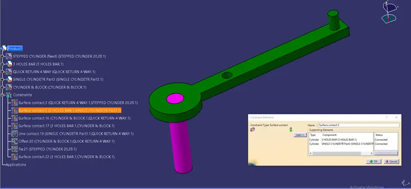
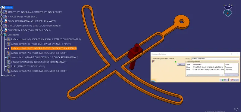
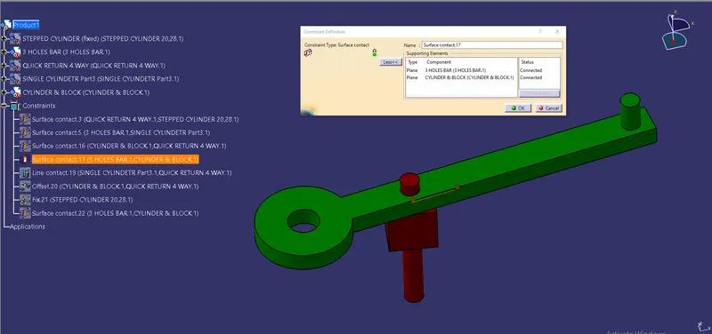
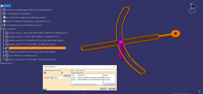
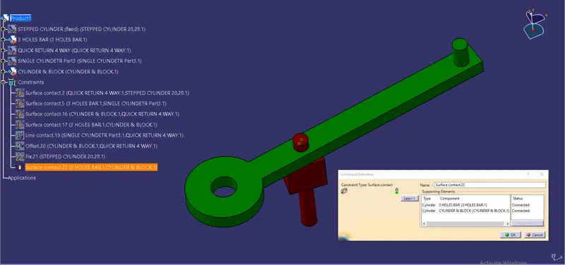
Offset Constraint
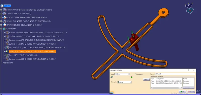
The Offset Constraint is used to place selected elements at an offset distance from
each other. It also makes the two planar faces parallel to each other. To invoke this
tool, choose the Offset Constraint button from the Constraints toolbar. After invoking
the tool, you are prompted to select the first geometric element for the Offset constraint.
Select a planar face, circular face, plane, axis, or a point from the geometry area. You are
prompted to select the second geometric element. Select a planar face of another component;
the Constraint Properties dialog box is displayed
Moving and Rotating Using the Manipulation Tool
The Manipulation tool is used to move or rotate the component freely by dragging
the cursor. To translate or rotate any component, choose the Manipulation button
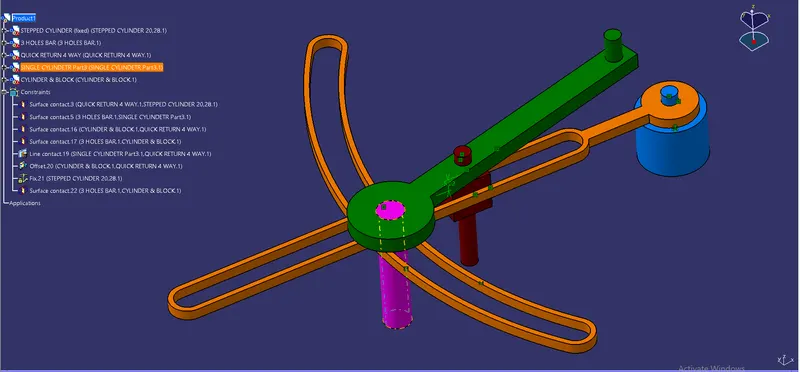
from the Move toolbar.after all the manipulations to the parts placements the image below shows the fuinal assembled part of QRM assembly.
The following video below shows the mechanism of the QRM assembly :
SUBMITTED FILES :
1.Part models(.CATPart), assembly file (.CATProduct) of QRM & CV JOINT ASSEMBLY
2.2D drawings both pdf and .CATDrawing of QRM & CV JOINT ASSEMBLY
Thank you