Week 1 Stress Concentration on a Plate with hole
Objective
- Compare the deformation and maximum stress developed on a structural steel model for the 2 cases
- Case 1: Plate with hole
- Case 2: Plate with 3 holes
2. From the analysis standpoint, select which of the two design cases performs well and explain the reason
3. From a manufacturing point of view, select which of the two designs is suitable for manufacturing and explain the reason
Introduction:
This report compares the performance of two designs of a structural steel plate with holes. The plate has dimensions of 300mm in length, 120mm in height, and 30mm in thickness. The first design features a circular hole with a diameter of 60mm located at the center, while the second design features two smaller holes with a diameter of 30mm located 90mm away from the center. The plate is fixed at the left face and subjected to a load of 500N on the right face. The results of finite element analysis (FEA) are used to compare the maximum deformation and maximum stress developed in each design
Deformation and stress results
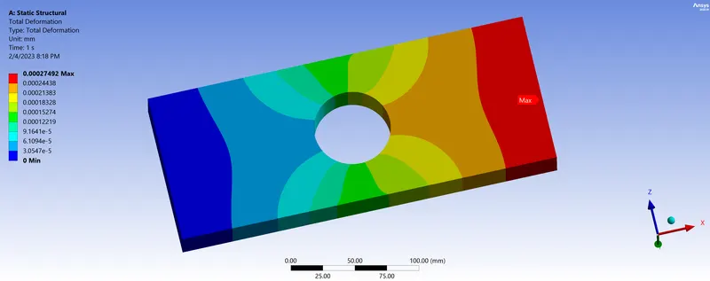
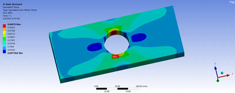
- Case 1: Plate with hole
Boundary conditions
- fixed at left side
- force of 500N on right side acting in the positive x direction.
The maximum deformation = .00027492mm
The maximum stress = .60679Mpa
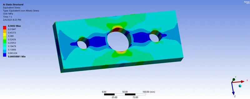
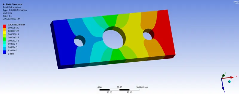
- Case 2 : Plate with 3 holes
Boundary conditions
- fixed at left side.
- force of 500N on right side acting in the positive x direction.
The maximum stress =.5832Mpa
The maximum deformation = .00029728mm
CONCLUSION:
Comparing the total deformation, stress, and strain developed in both cases.
- The deformation developed in case 2 is 0.00029728mm which is more than case 1 is 0.00027492mm because of the number of holes present in Case 2 deformations occur more.
- The Equivalent stress developed in case 1 is 0.60656mpa and case 2 is 0.58123mpa as the stress developed in case 1 is more as compared to case 2 due to the number of holes present in case 2 that acts as a stress reliever.
1. Analysis point of view:
The maximum stress in case 2 is comparatively lower than in case 1. Due to the number of holes present in case 2, stress and strain distribution in an overall plate is lesser than stress and strain distributed in the center hole model. From an analysis point of view, case 2 is better than case 1.
2. Manufacturing point of view:
The production depends on many factors such as machinery, manpower, production cost, time, etc. While comparing both cases, case 2 is less preferable because it has three holes which increases the machine operating cost, production time, production cost and it also increases scrap whereas case 1 with a single hole is efficient to get production with lesser production time, production cost and scrap material.
CONCLUSION:
Thus a plate with hole considering both case setup conditions has been designed and structurally analysed considering the boundary condition to determine the stress concentration.