Week 1 Stress Concentration on a Plate with hole
STRESS CONCENTRATION IN A PLATE WITH HOLE
OBJECTIVE
1. To design a plate with hole for the following cases,
- Case(1): Length=300mm, height=120mm, thickness=30mm, circular hole at the center with diameter=60mm.
- Case(2): The dimensions are similar to case 1, but additional two smaller holes of diameter=30mm away from center.
2. To determine and compare the maximum deformation and stress developed on a structural steel model for the 2 cases.
3. To select the design from an analysis standpoint.
4. To select the design from a manufacturing standpoint.
1. THEORY
1.1 Stress concentration:
Whenever a machine component changes the shape of its cross-section, the simple stress distribution no longer holds good and the neighbourhood of the discontinuity is different. It occurs for all kinds of stresses in the presence of fillets, notches, holes, keyways, splines, surface roughness or scratches etc.
Stress concentration is defined as the localization of high stresses due to the irregularities present in the component and abrupt changes of the cross section. In order to consider the effect of stress concentration and find out localized stresses, a factor called stress concentration factor is used. It is denoted by Kt and defined as,
Kt=σmaxσo=τmaxτoKt=σmaxσo=τmaxτo
where σo and τo are stresses determined by elementary equations and σmax and τmax are localized stresses at the discontinuities. The subscript ‘t’ denotes the ‘theoretical’ stress concentration factor. The magnitude of stress concentration factor depends upon the geometry of the component.
The causes of stress concentration are as follows:
- Variation in Properties of Materials
- Load Application
- Abrupt Changes in Section
- Discontinuities in the Component
- Machining Scratches
1.2 Methods to reduce stress concentration:
Although it is not possible to completely eliminate the effect of stress concentration, there are methods to reduce stress concentrations. This is achieved by providing a specific geometric shape to the component.
There are different methods to reduce the bending of the stress lines at the junction and reduce the stress concentration. In practice, reduction of stress concentration is achieved by the following methods:
- Additional Notches and Holes in Tension Member
- Providing Fillet Radius, Undercutting and Notch for Member in Bending
- Drilling Additional Holes for Shaft
- Reducing shank diameter in Threaded Members
2. ANALYSIS SETUP
2.1 Geometry:
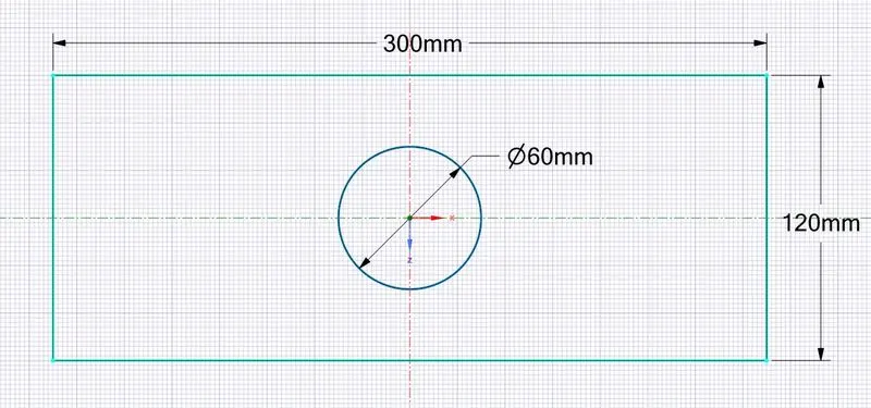
a) plate with single hole.
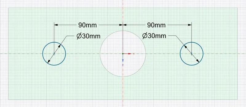
b) plate with three holes.
Fig.2.1.1 2D sketch of Plate with hole.
The 2D sketch of plate with a hole having length=300mm, height=120mm and circular hole at the center with diameter=60mm is created using tools under sketch option in SpaceClaim. Similarly, for case 2, with same dimensions of case 1, additional 2 smaller holes are created, having diameter=30mm away from center with distance of 90mm.
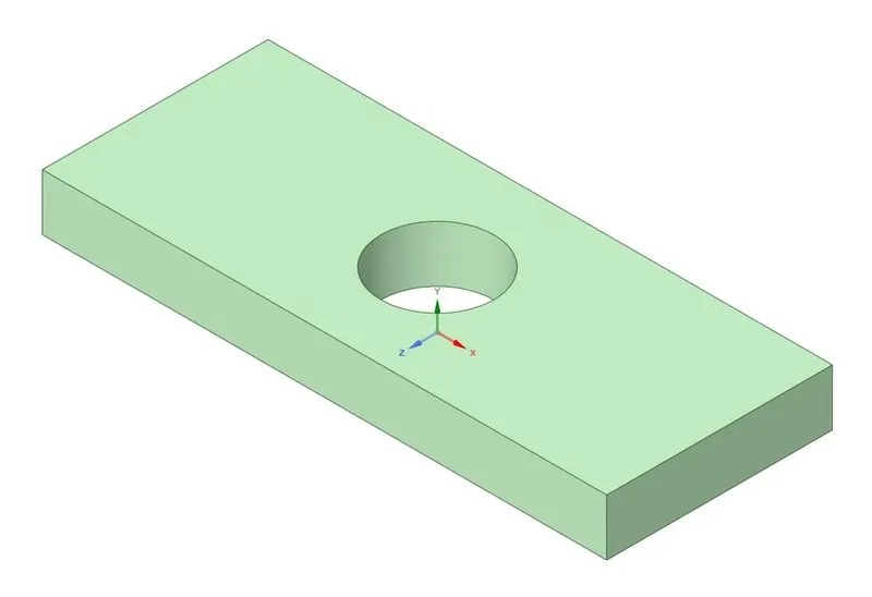
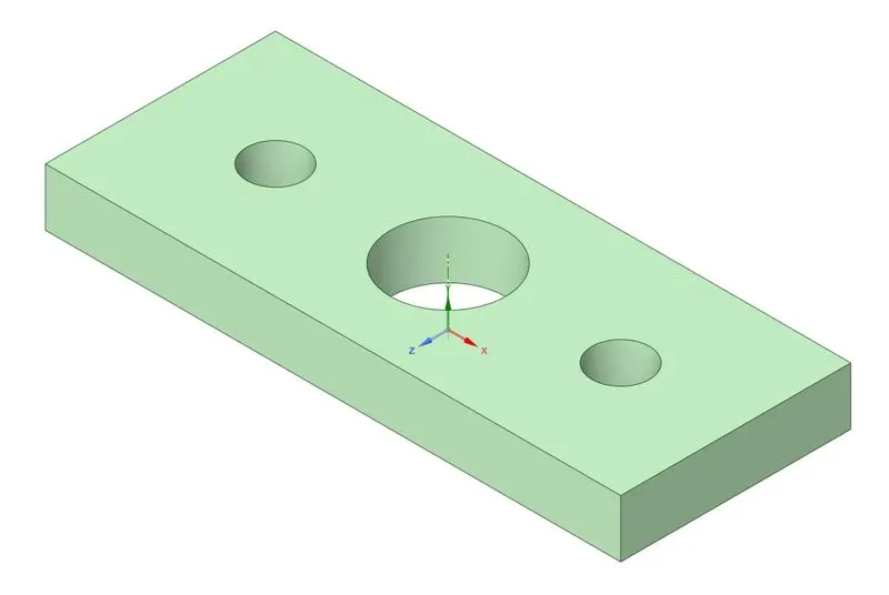
a) plate with single hole. b) plate with three holes.
Fig.2.1.2 3D model of Plate with hole
The 2D sketch of case 1 and 2 are extruded using pull option with a thickness=30mm as shown in fig.2.1.2.
2.2 Material Properties:
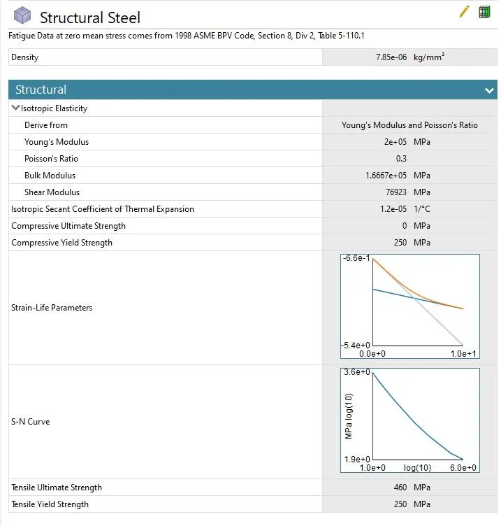
Fig.2.2 Material property details.
The material used for both the models is structural steel with the necessary parameters as shown in fig.2.2.
2.3 Meshing:
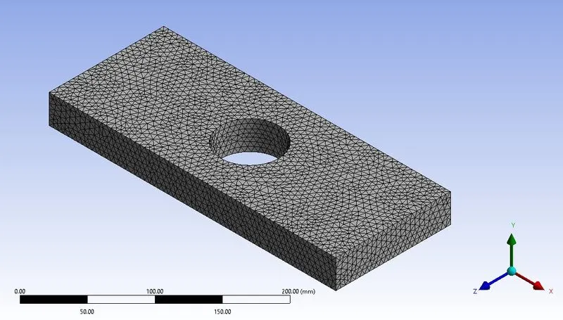
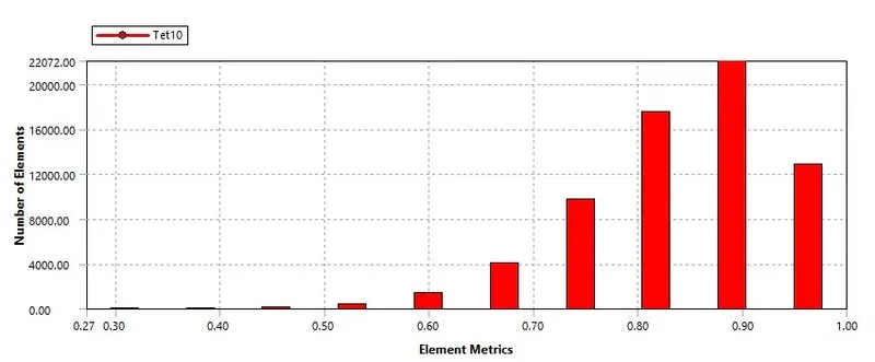
a) plate with single hole.
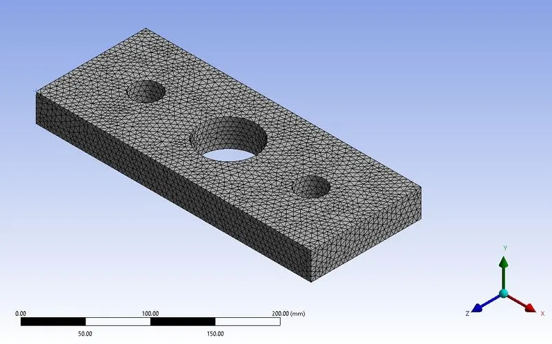
b) plate with three holes.
Fig.2.3 Meshing details
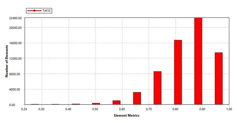
The 3D model of case 1 and 2 are meshed using tetrahedral elements. The element metrics graph shows the quality of the elements are good and a greater number of elements are in between the range of 0.7 and 1.0. The minimum element size of 5mm was considered for both the models. Since, the academic version of software has the problem size limit of 128k nodes or elements. The mesh statistics of the models is tabulated as shown below.
|
Node No. |
Element No. |
|
|
Case-1 |
99117 |
67934 |
|
Case-2 |
95892 |
65265 |
2.4 Boundary Conditions:

a) plate with single hole.
b) plate with three holes
Fig.2.4 Boundary conditions
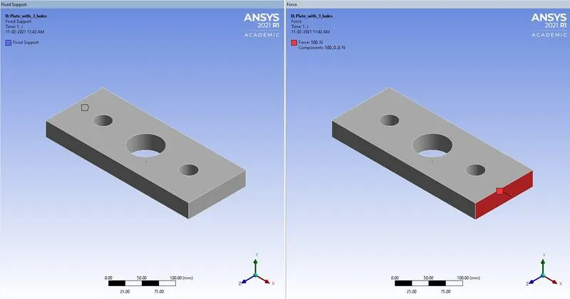
The left side face of both the models is fixed and a force of 500 N is applied to the right side face of the models.
3. RESULTS AND DISCUSSIONS
3.1 Von-Mises stress distribution:
a) plate with single hole.
b) plate with three holes.
Fig.3.1 Von-Mises stress distribution.
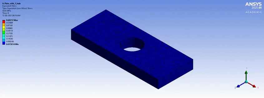
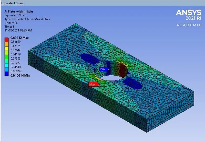
From the v-m stress contour plot for case-1, it is observed that the maximum stress of 0.60212 MPa is developed around the hole region having minimum cross-sectional area and material. The minimum stress of 0.015014 MPa is developed around the hole region having maximum cross-sectional area and material.
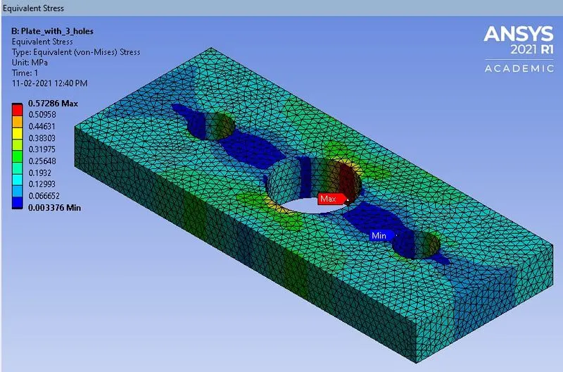
From the v-m stress contour plot for case-2, it is observed that the maximum stress of 0.57286 MPa is developed around the larger hole region having minimum cross-sectional area and material. The minimum stress of 0.003376 MPa is developed around the smaller hole region having maximum cross-sectional area and material
3.2 Total Deformation:
a) plate with single hole.
total deformation 3total deformation 3
b) plate with three holes.
Fig.3.2 Total Deformation
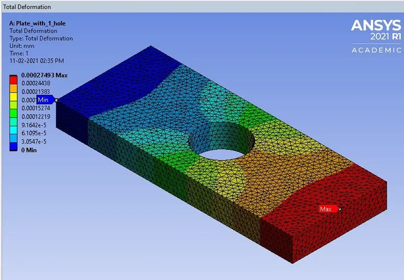
From the deformation contour plot for case-1, it is observed that the maximum deformation of 2.7493E-4 mm has occurred around the loading face of the model.
From the deformation contour plot for case-2, it is observed that the maximum deformation of 2.9728E-4 mm has occurred around the loading face of the model.
3.3. Comparison of results:
The maximum and minimum values of v-m stress and total deformation is tabulated as shown below.
|
|
v-m stress (MPa) |
Total Deformation (mm) |
||
|
Max. |
Min. |
Max. |
Min. |
|
|
Case-1 |
0.60212 |
0.015014 |
2.7493E-4 |
0 |
|
Case-2 |
0.57286 |
0.003376 |
2.9728E-4 |
0 |
The maximum value of v-m stress is developed in the case-1 i.e., plate with single hole because of sudden deviation of stress flow lines around the hole and minimum material in the region of hole. The minimum value of v-m stress is developed in case-2 i.e., plate with three holes because of gradual deviation of stress flow lines around the smaller hole to the larger hole.
The maximum deformation has occurred in case-2 i.e., plate with three holes because of minimum material condition due to three holes.
3.4. Design selection from the standpoint of analysis.
From the standpoint of analysis, the design of plate with three holes i.e., case-2 is preferred because v-m stress developed around the holes is less compared to case-1 design. The stress concentration is less in the case-2 design compared to case-1 design. The computational time required is also less for case-2 design compared to case-1 design.
3.5. Design selection from the standpoint of manufacturing.
From the standpoint of manufacturing, the design of plate with single hole i.e., case-1 is preferred because the design is simple for manufacturing, only one hole is required to be drilled in the plate as compared to case-2 design. The manufacturing time and labour cost can be minimized by preferring case-1 design. The stiffness of case-1 design is more compared to case-2 design because total deformation occurred in case-1 design is less compared to case-2 design.
CONCLUSION
- The plate with circular hole is designed for two cases i.e., case (1): plate with single hole, case (2): plate with three holes using SpaceClaim.
- The models are meshed using tetrahedral elements with minimum element size being 5mm due to problem size limit imposed on academic version of software.
- The models are solved for v-m stress and total deformation by applying appropriate boundary conditions.
- The maximum value of v-m stress is developed in the case-1 i.e., plate with single hole
- The maximum deformation has occurred in case-2 i.e., plate with three holes
- From the standpoint of analysis, the design of plate with three holes i.e., case-2 is preferred because stress concentration around hole is less compared to case-1 design.
- From the standpoint of manufacturing, the design of plate with single hole i.e., case-1 is preferred because the design is simple for manufacturing.