Week 1 Stress Concentration on a Plate with hole
STRESS CONCENTRATION ON A HOLE
OBJECTIVE:
The objective of this challenge is to design a plate with single hole and multi hole, and to Simulate the two cases and compare its deformation and maximum stress results. As well as to STATE that among the two cases, which case will prefer for Analysis and which case will prefer the manufacturing process.
SOFTWARE USED:
Space claim for design
ANSYS Workbench and ANSYS Mechanical for Analysis
Introduction
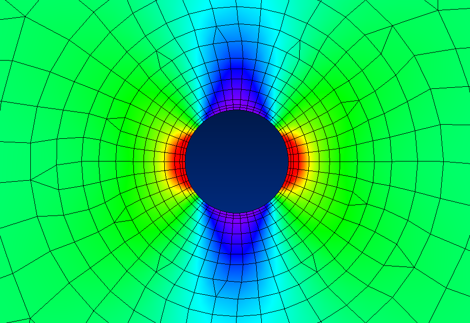
The story of the analysis of stress concentrations begins in 1898 with Ernst Gutav Kirsch's linear elastic solution for stresses around a hole in an infinite plate. Kirsch's solution contains the well known factor-of-three stress concentration at the hole under uniaxial loading. But there is more to the story. The stress concentration can in fact vary from two to four for more complex loading conditions, i.e., stress states different from uniaxial tension.
THEORY:
A thin rectangular plate under a uniaxial tension has a uniform stress distribution. Introducing a circular hole in the plate disturbs the uniform stress distribution near the hole, resulting in a significantly higher than average stress. Such a thin plate, subject to in-plane loading, can be analyzed as a 2-D plane-stress elasticity problem. In theory, if the plate is infinite, then the stress near the hole is three times higher than the average stress. For a rectangular plate of finite width, the stress concentration factor is a function of the ratio of hole diameter to the plate width.
PROCEDURE:
Case :1 Stress Concentration on a Plate with single center hole
1. Open the ANSYS Workbench software. Under the Analysis system select the Static structural and wait for few seconds to pop up the window, which contains Engineering data, Geometry, Model, setup, Solution and Results.
2. Rename the static structural as Plate with hole.
3. Update the Default material (Structural steel) to the System, under the Engineering data.
4. Design a rectangular plate with hole by using space claim and assign the Dimensions such as
Plate dimensions:
Length=300mm
Height=120mm
Thickness=30mm
Circular Hole at the center:
Diameter=60mm
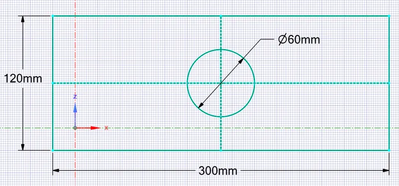
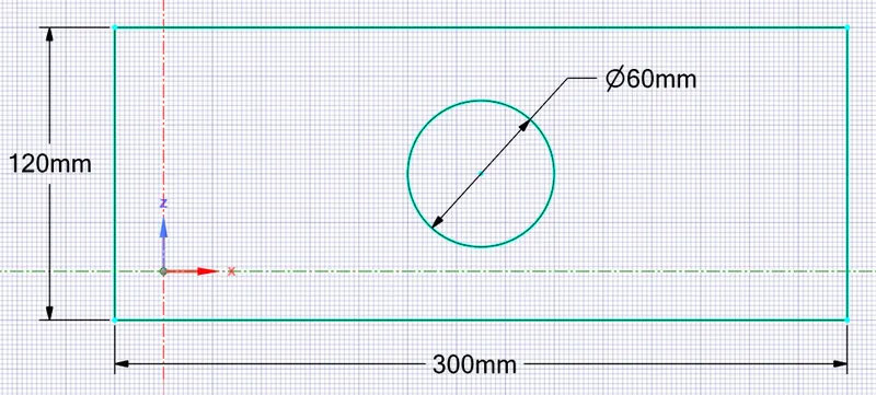
By using pull option assign the thickness of the plate as 30mm.
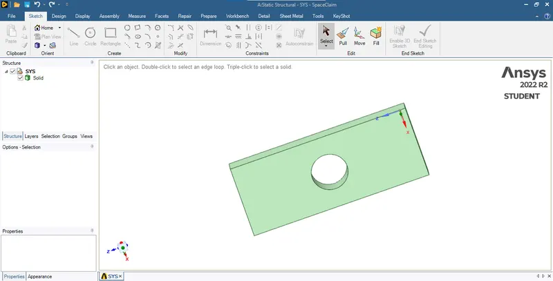
5. Update the model by right click and edit the Model for meshing.
6. Wait for few seconds and ANSYS Mechanical will open as shown below.
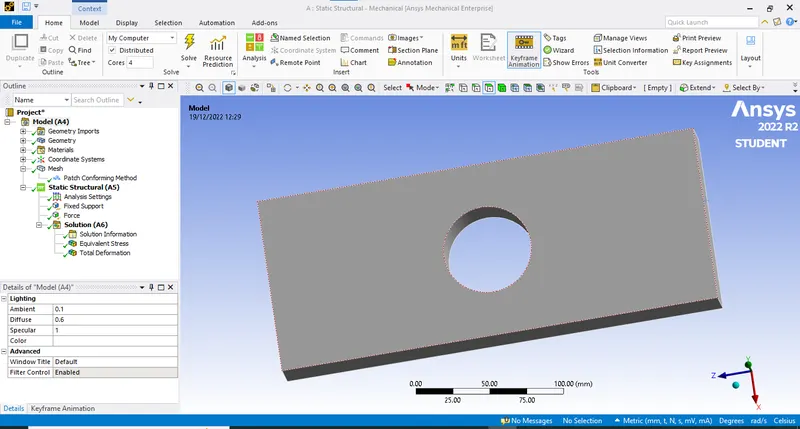
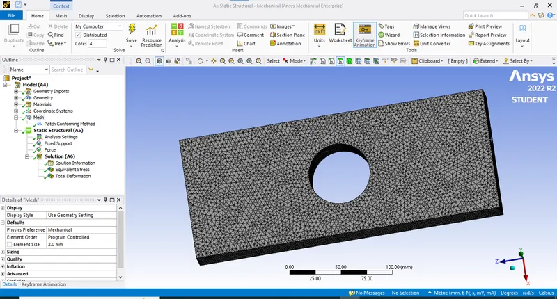
7. In ANSYS automatic mesh will be performed with Default mesh size and change the mesh size as 2mm.
Be aware of ANSYS Student Edition and don't go beyond the size limit.
As it is a solid structure we have to change the 2D Element to 3D Element. So click on mesh and select the insert option. Under insert option select the method and slect the gemetry as well as under the method, select the tetrahedrons.
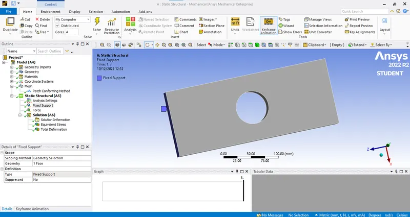
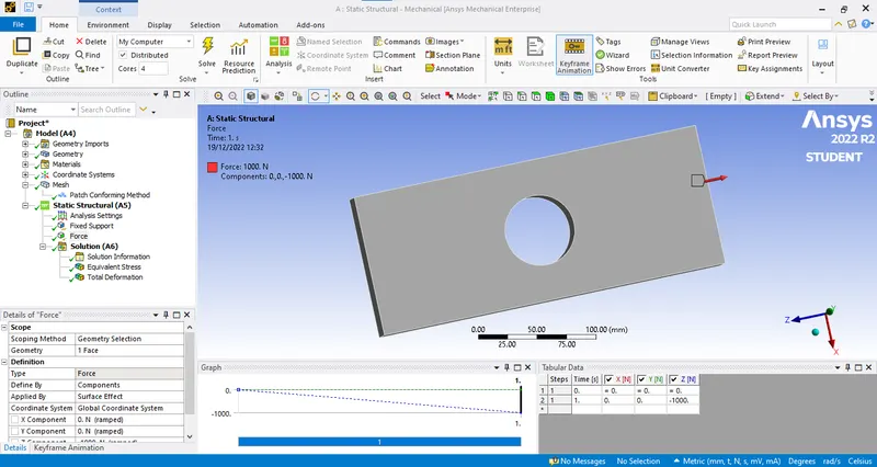
8. In order to get the results we have to fix the left end of the plate by using the fixed support option and apply the tensile force at right side of the plate.
Fix the left end of the plate by using the fixed support option.
Apply the force at right end of the plate as a load of 500N
9. SOLVE the solution and we can see the simulation run under soluion information.
10. Then request for the output results such as equivalent (von-mises) stress and total deformation.Finally evaluate all results.
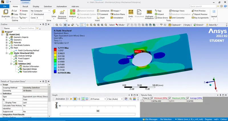
FIG: Equivalent (von-mises) stress
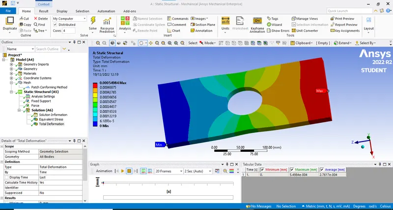
FIG: Total deformation
Case :2 Stress Concentration on a Plate with MULTIPLE holes
1. Open the ANSYS Workbench software. Under the Analysis system select the Static structural and wait for few seconds to pop up the window, which contains Engineering data, Geometry, Model, setup, Solution and Results.
2. Rename the static structural as Plate with hole.
3. Update the Default material (Structural steel) to the System, under the Engineering data.
4. Design a rectangular plate with hole by using space claim and assign the Dimensions such as
Plate dimensions:
Length=300mm
Height=120mm
Thickness=30mm
Circular Hole at the center:
Diameter=60mm
Smaller holes 90mm away from the center:
Diameter = 30mm
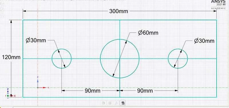
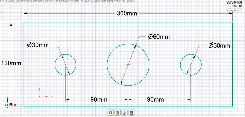
By using pull option assign the thickness of the plate as 30mm.
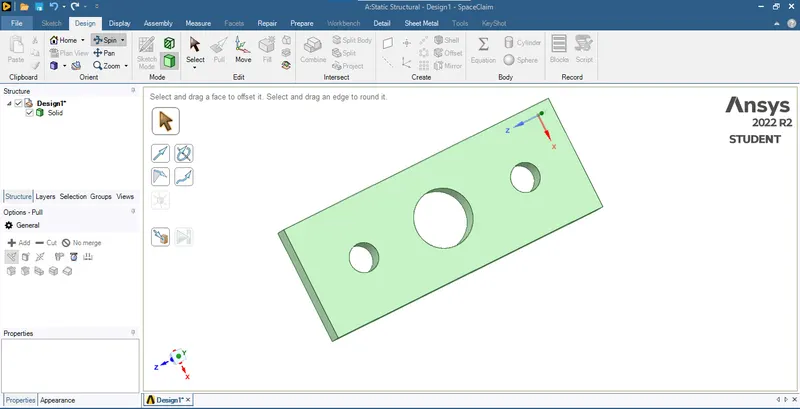
5. Update the model by right click and edit the Model for meshing.
6. Wait for few seconds and ANSYS Mechanical will open as shown below.
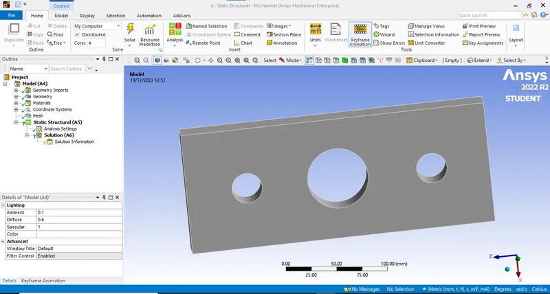
7. In ANSYS automatic mesh will be performed with Default mesh size and change the mesh size as 2mm.
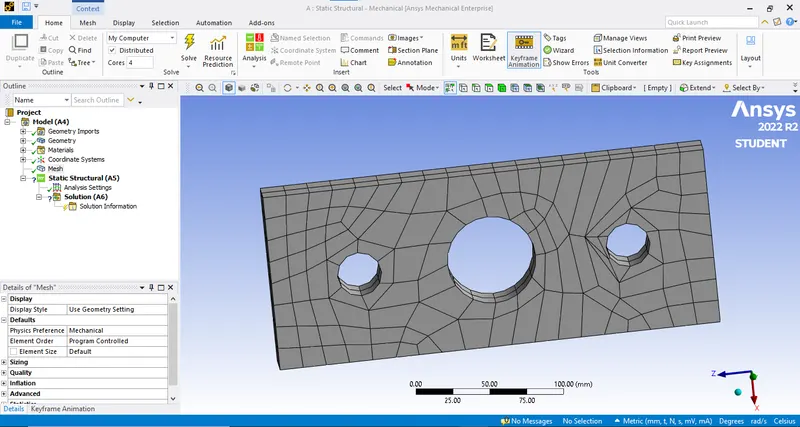
Be aware of ANSYS Student Edition and don't go beyond the size limit.
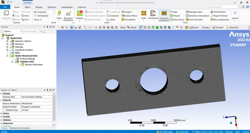
As it is a solid structure we have to change the 2D Element to 3D Element. So click on mesh and select the insert option. Under insert option select the method and slect the gemetry as well as under the method, select the tetrahedrons.
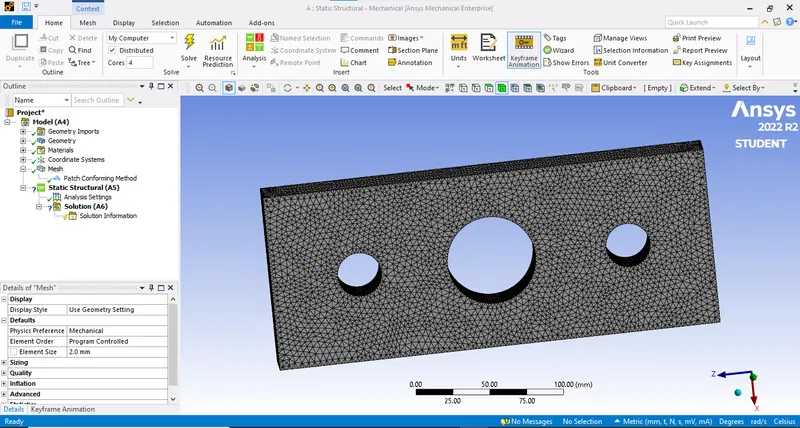
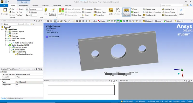
8. In order to get the results we have to fix the left end of the plate by using the fixed support option and apply the tensile force at right side of the plate.
Fix the left end of the plate by using the fixed support option.
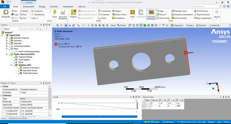
Apply the force at right end of the plate as a load of 500N
9. SOLVE the solution and we can see the simulation run under soluion information.
10. Then request for the output results such as equivalent (von-mises) stress and total deformation.Finally evaluate all results.
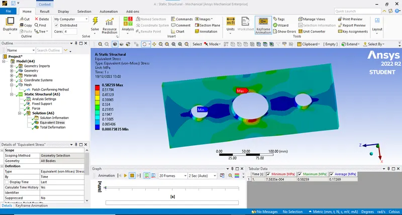
FIG: Equivalent (von-mises) stress
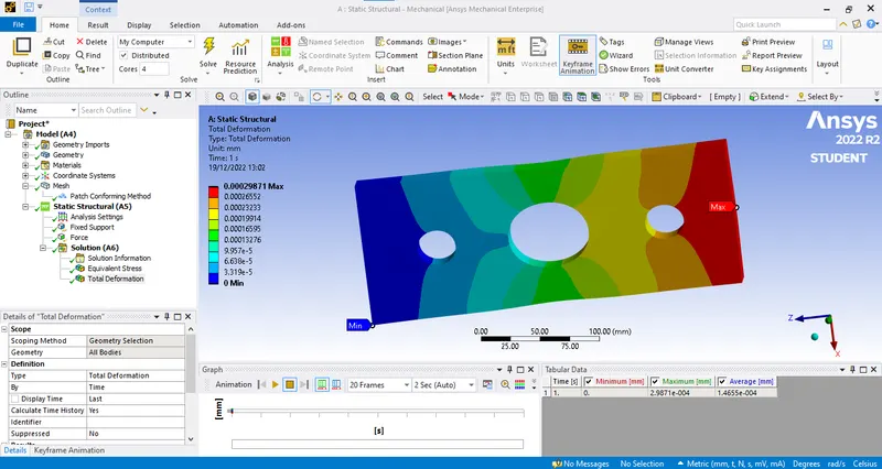
FIG: Total deformation
RESULTS COMPARISM:
Comparision of the deformation and maximum stress developed on a structural steel model of two cases.
|
CASES |
Deformation (mm) |
maximum stress (MPa) |
|
Case-1 |
1.2111 |
0.00054984 |
|
Case-2 |
0.0002987 |
0.58259 |
From the above table the deformation in the second case (Stress Concentration on a Plate with MULTIPLE holes) is high when compared to first case(Stress Concentration on a Plate with single center hole). Where as For Maximum stress, it will be high in first case(Stress Concentration on a Plate with single center hole) when compared with the second case(Stress Concentration on a Plate with MULTIPLE holes).
Selection of Design from the analysis point of view
From the analysis point of view, we can select the case-2 (Stress Concentration on a Plate with MULTIPLE holes)
EXPLANATION:
The main ajenda of any analysis is to reduce the stress, based on that in our two cases, case-2 will have less stress when compared with case-1. For that reason we had selected the case-2 in analysis point of view.
Selection of Design from the Manufacturing point of view
From the Manfacturing point of view, we can select the case-1 (Stress Concentration on a Plate with single center hole)
EXPLANATION:
The main ajenda of any manufacturer is to reduce the wastage of material as well as to reduce the production time. So the first case is very simple in design and requires less time for manufacturing as well as wastage of material will be less, where as in case-2 it requires more time for manufacturing as well as wastage of material will be high. For that reason we had selected the case-1 in Manfacturing point of view.