Week 1 Stress Concentration on a Plate with hole
Objective: To analysis and determine the sound engineering judgment on both cases mentioned below by using the Ansys Work Bench.
Case 1: Plate with Hole
Dimensions: Breadth 120mm X Length 300mm X 30mm Thk.
Geometry Description: Hole of Dia. 60mm with 30mm depth punched at center of rectangular plate.
Loads Consideration: Fixed at one end at 120mm side, Load tensile load 500N at other end.
Material: Structural Steel.
Case 2: Plate with Multiple Holes
Dimensions: Breadth 120mm X Length 300mm X 30mm Thk.
Geometry Description: Hole of Dia. 60mm with 30mm depth punched at center of rectangular plate. Two holes of Dia. 30mm offset of 90mm from center at either sides.
Loads Consideration: Fixed at one end at 120mm side, Load tensile load 500N at other end.
Material: Structural Steel.
Procedure:
- Create geometry in ansys or any modeling software for both the cases 1 & 2, import the same in static structural analysis in ansys.
- Assign the Materials properties, assuming the structural steel.
- Mesh the Geometry; assign the fixed load at one end and 500N away from the face i.e. tensile loading.
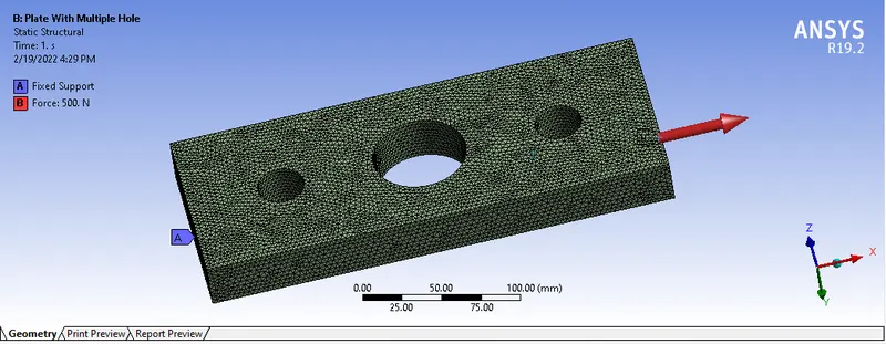
4. Solve the analysis and generate the evaluate results such as deformation and stress, which are necessary.
Results
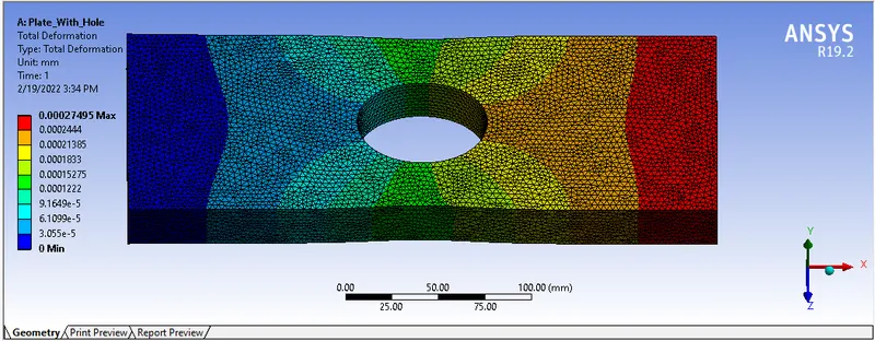
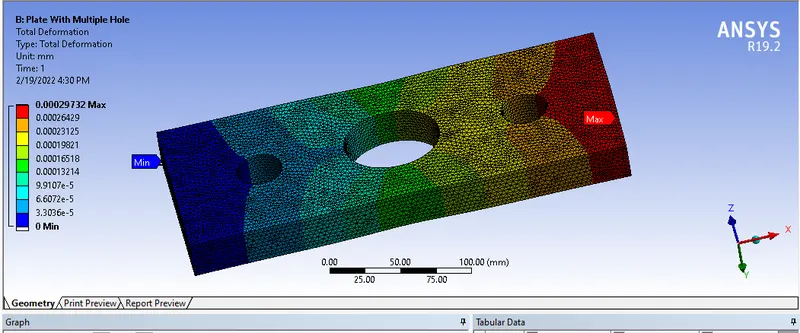
1. Maximum deformation in mm
Case : 1
Case : 2
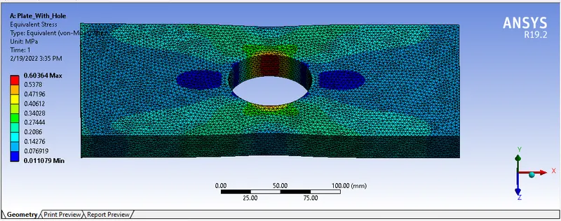
Max. Equivalent Stresses
Case 1 :
Case 2:
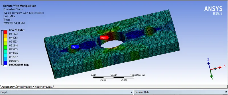
Report :
| Case 1 | Case 2 | |
| Max. Deformation in mm | 0.00027 | 0.00029 |
| Min. Deformation in mm | 0 | 0 |
| Max. Equivalent Stress in MPA | 0.603 | 0.577 |
| Min. Equivalent Stress in MPA | 0.011 | 0.0009 |
Analysis Point of Selection:
Initially in both cases Stresses are within the limit, not exceeded the Yield strength both is in safe. Generally additional side holes are given to a plate to reduce the large amount of stress acting on center hole which is used for connections or bolted hole. And in least case of failure with deformation in case 2 hole at right will changes is shape then center hole i.e. hole alignment and shape is not deformed. Further, the results which are generated case 2 having less stress induced , less deformation. If Weight is parameter of which effect the entire analysis of full component, reducing the weight is good engineering practice.
Manufacturer Point of Selection:
Generally so many parameters are involved in selection of either case 1 or Case 2, following are described here,
- Based on manufacturing time and effort, case 1 will be selected over case 2 because of less machining of holes into a plate.
- If manufacturer providing the cost is based on weight of finished material to purchaser then case 2 having the less weight so lesser cost then the case 1.