Week 1 Spur Gear Challenge
OBJECTIVE:
To perform static structural analysis on spur gear with different materials as shown below -
Case 1 : Cast Iron (Ductile)
Case 2 : Cast Bronze
Case 3: Cast Steel
To to find Equivalent stress, Total deformation and Stress intensity for above three cases and recommending choice of material by comparing the results.
1. Stress Intensity, Stress Intensity Factor (K) and Fracture developement in specimen -
Stress Intensity in other words is the Stress State near the tip of a crack or notch caused by a remote load or residual stresses. The term Stress Intensity Factor (K) is used in fracture mechanics to predict stress intensity at given location caused by applied loads and generated stresses. Stress Intensity Factor is a theoretical concept usually applied to a homogeneous, linear elastic material and is useful for providing a failure criterion for brittle materials, and is a critical technique in the discipline of damage control. The concept can also be applied to materials that exhibit small scale yielding at a crack tip.
The magnitude of K depends on specimen geometry, the size and location of the crack or notch, and the magnitude and the distribution of loads on the material. It can be written as :-

where f(a/W) is a specimen geometry dependent function of the crack length, a, and the specimen width, W, and `σ` is the applied stress.
The traditional approach to the design and analysis of a part is to use strength-of-materials concepts. In this case, the stresses due to applied loading are calculated. Failure is determined to occur once the applied stress exceeds the material's strength (either yield strength or ultimate strength, depending on the criteria for failure).
In fracture mechanics, stress intensity factor is calculated as a function of applied stress, crack size, and part geometry. Failure occurs once the stress intensity factor exceeds the material's fracture toughness. At this point the crack will grow in a rapid and unstable manner until fracture.
2. Analysis Set up for Spur Gear
2.1 Geometry
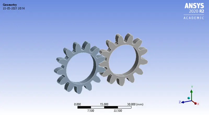
The CAD model of spur gear is imported in ansys static structural environment. Both the driver and driven gear have 13 teeths. The gear on the left is called Left Spur and the on the right is called Right Spur.
2.2 Material Property
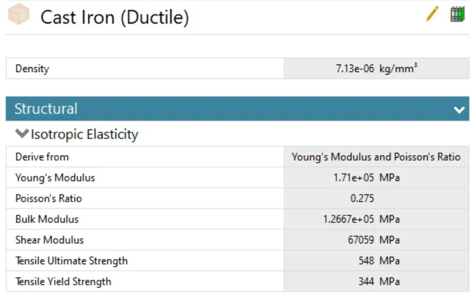
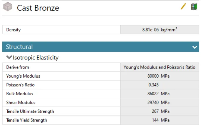
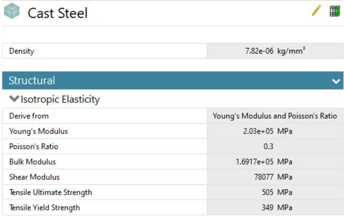
Below three materials are used for analysis of spur gear. The analysis is carried out for each material individually
- Case 1 - Cast Iron (Ductile)
- Case 2 - Cast Bronze
- Case 3 - Cast Steel
The Detailed Engineering Data of each material is as shown in the below image:-
2.3 Connection Details
(a) Contact Details :
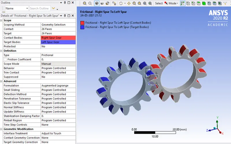
Frictional contact is given between faces of left and right spur gear as seen in the image below. The 26 faces on tooth of each gears are selected as these surfaces are sure to come in contact, the other surfaces on the gear tooth can be neglected as contact surface is negligible. The formulation is changed to Augumented Lagrange to minimize the interference errors. The interference treatment is changed to adjust to touch to avoid penetration.
(b) Joint Details :
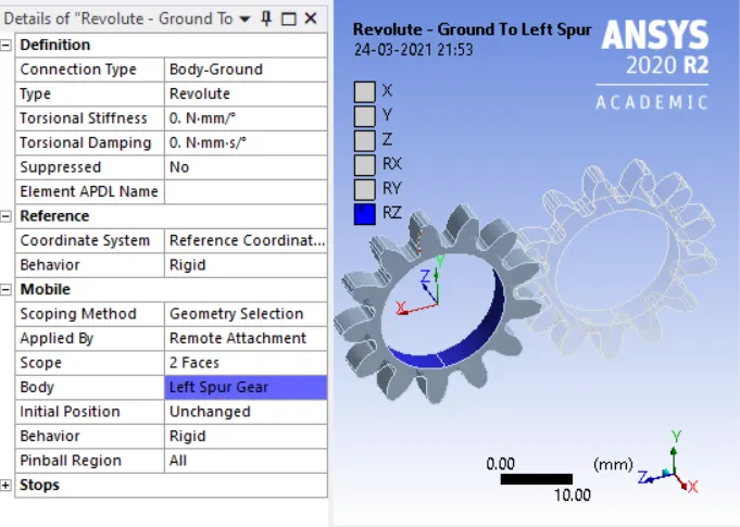
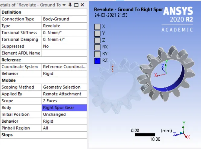
Both left and right spur gear are given revolute joint about its axis with Body-Ground type connection.
2.4 Mesh
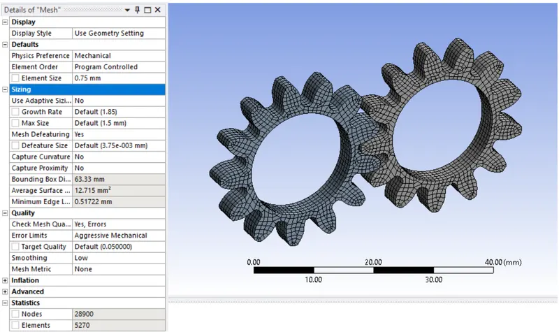
Program controlled mesh of element size 0.75mm is used for all the three cases. A fine mesh is generated with 28900 nodes and 5270 elements which is sufficient to carry out simulation giving desired results.
2.5 Boundary Conditions and Analysis Settings :
(a) Analysis Settings :
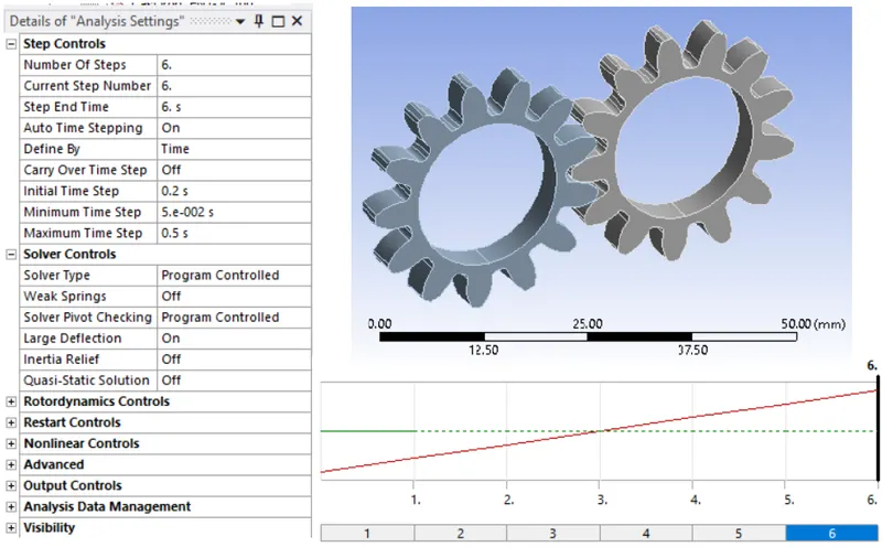
For this analysis total number of steps is set to 6 with Auto Time Stepping set to ON. The Initial time step is set to 0.2 seconds with minimum and maximum time step as 0.05 and 0.5 seconds respectively. In solver controls Large deflection option is set On, so as to account for changes in stiffness due to changes in shape of the gears.
(b) Joint Load Details :
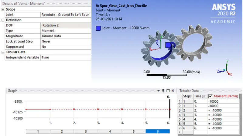
- Left Gear -
Left Spur Gear is the driving gear, hence a anticlockwise moment of 10 N-m is applied to it.
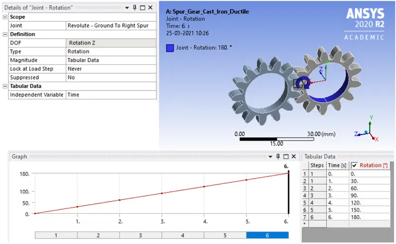
- Right Gear -
Right spur gear is driven by left gear, hence a clockwise rotation of 180 degrees is given to it with increment of 30 degrees in 6 steps.
2.6 Post Processing and Results
Spur Gear is analyzed for three materials viz Cast Iron (Ductile), Cast Bronze and Cast Steel for Equivalent Stress, Total Deformation, Equivalent Elastic Strain and Stress Intensity. The results for each case is as below.
(a) Case 1 - Cast Iron (Ductile)
(1) Equivalent Stress
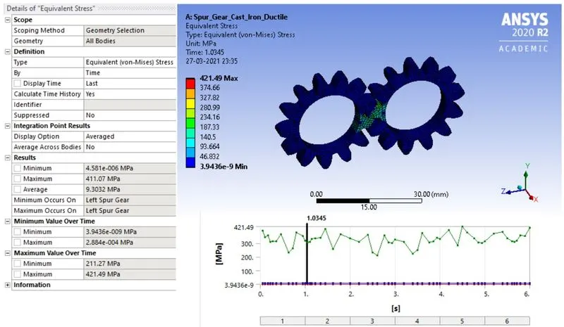
Animated Results - https://drive.google.com/file/d/17opOkppzTfjX5cP2Gp0nX8WVo6SIYBou/view?usp=sharing
(2) Total Deformation
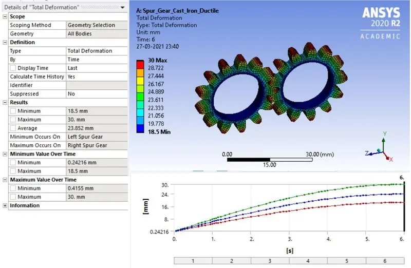
Animated Results - https://drive.google.com/file/d/1GN5jh9MtRyOiQTt55x9Kv34ZOPiznhyr/view?usp=sharing
(3) Equivalent Elastic Strain
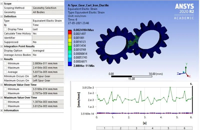
Animated Results - https://drive.google.com/file/d/1tTtXzcKKcy81oBp6RD22pEwrOzN_Lajb/view?usp=sharing
(4) Stress Intensity
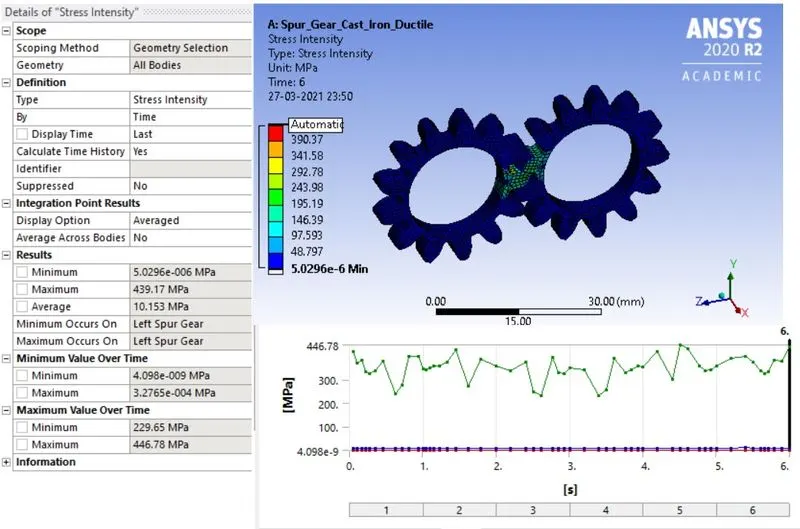
Animated Results - https://drive.google.com/file/d/1jTvoEoEN6pbMX2WccuTXBxyk22x9fAjP/view?usp=sharing
(b) Case 3 - Cast Bronze
(1) Equivalent Stress
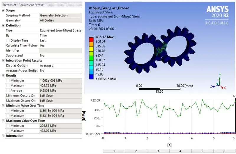
Animated Results- https://drive.google.com/file/d/1NDHOQK_-mKV4wPSKZ2Z85CnrTa5gOMxD/view?usp=sharing
(2) Total Deformation
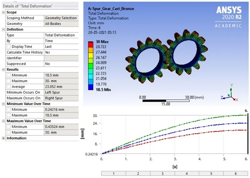
Animated Results- https://drive.google.com/file/d/10k8uhIHasGa9imFkb8FTDs6zyOKJNIM6/view?usp=sharing
(3) Equivalent Elastic Strain
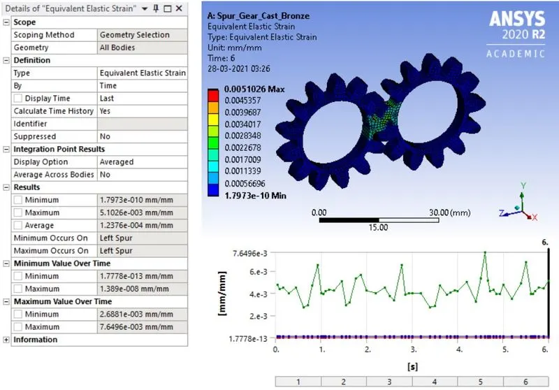
Animated Results- https://drive.google.com/file/d/1EaeTLQByc7LVNd-LSE-sRlQj4ltPvQYV/view?usp=sharing
(4) Stress Intensity
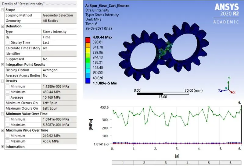
Animated Results - https://drive.google.com/file/d/1kPr3NDMseOu8WzVsuOIVNNPcgOE9dpx2/view?usp=sharing
(c) Case 3 - Cast Steel
(1) Equivalent Stress
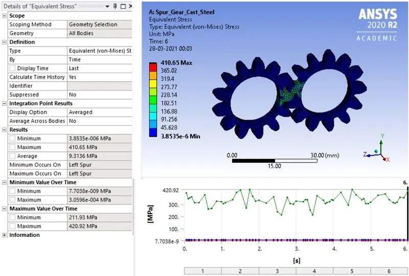
Animated Results - https://drive.google.com/file/d/1cGiRvdvZGUq0rMW8fMQ9t75mJqnT9-u1/view?usp=sharing
(2) Total Deformation
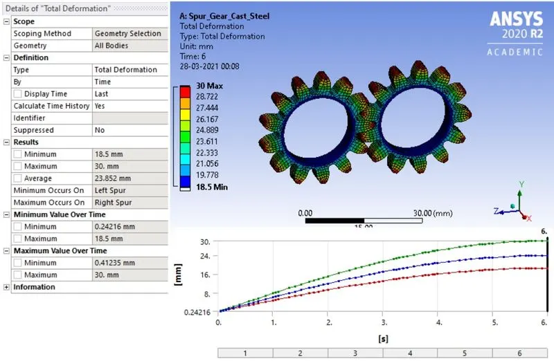
Animated Results - https://drive.google.com/file/d/1QSpjFPhIasYmLSRpF0sRP5UFU_Knuhgy/view?usp=sharing
(3) Equivalent Elastic Strain
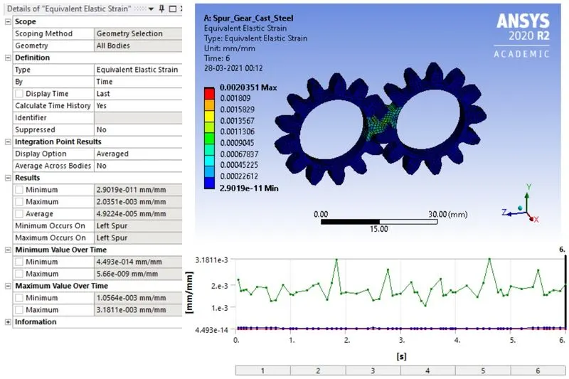
Animated Results - https://drive.google.com/file/d/1WfvWOVZiKk9ge3-xMMUOUckp9nhxIiLy/view?usp=sharing
(4) Stress Intensity
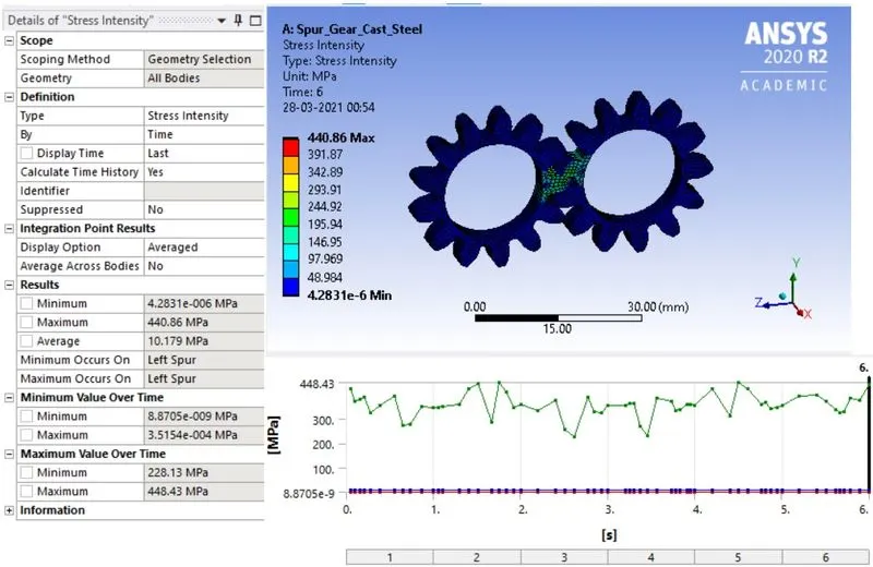
Animated Results - https://drive.google.com/file/d/1PwVcwNSqcGpsZ2wujWof6dLCkKaslZP4/view?usp=sharing
2.7 Post Processing Results and Summary
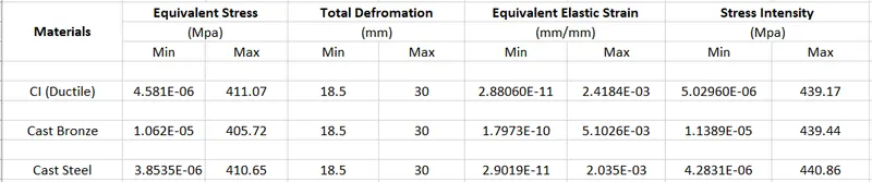
Results and conclusion -
- Equivalent stress is lowest in Cast Bronze as compared to other material.
- The minimum and maximum value of Total deformation is same in all cases.
- Equivalent Elastic Strain is highest in Cast Bronze as compared to other two materials.
- Stress Intensity is maximum in Cast Steel.
After analyzing and comparing above results, we can see that Equivalent stress generated is less in Cast Bronze as compared to other materials but yield strength and ultimate strength is lowest for Cast Bronze. As a result Cast Bronze will fail first among all the cases. Now we are left with two materials CI (Ductile) and Cast Steel which have max Equivalent Stresses as 411.07 and 410.65 MPa respectively. The ultimate tensile strength values for Cast Iron is higher than that of Cast Steel. The Stress Intensity Value for CI is the lowest. Also there is not a huge difference in Strain Values of these two materials. Hence when crack will generate in CI (Ductile) it will slowly increase but till then the Gears will keep on running as ultimate tensile strength value is higher as compared to Cast Bronze.
Therefore from above results we can say, even though Equivalent Stress generated is higher in Cast Iron (Ductile), it is the most suited material for this application as its ultimate strength is higher which will result in its operation till rupture. Also Cast Iron (Ductile) is easy to machine as compared to other materials and has good wear resistance which makes it more practical for this application.