Week 1- Mixing Tee
Aim: To simulate the flow of air through a mixing tee and study the mixing effectiveness of this in pipes of different length and
different momentum ratio.
Theory: In industrial process engineering, mixing is a unit operation that involves the manipulation of a heterogeneous physical
system with the intent to make it more homogeneous.Mixing is performed to allow heat or mass transfer to occur between one
or more streams, components, or phases. Modern industrial processing almost always involves some form of mixing. Mixing
Tess is a type of mixing mechanism. Mixing Tee utilizes a specifically engineered internal geometry to efficiently mix two fluid
streams into one combined stream. Mixing tees are widely used in the petrochemical, HVAC industry, etc, in which two fluids
streams with different physical or chemical properties mix together.
Hot air flowing in the main pipe is mixed with cold air flowing through a tee. The standard deviation of temperature is computed
to quantify the degree of mixing. The velocity and temperature fields are also computed. The effects of the mesh size,
turbulence model on results were examined. For this, we have created two versions of the mixing tee. One of them is longer
than the other.
Condition:
Your job is to set up steady-state simulations to compare the mixing effectiveness when hot inlet temperature is 360C & the Cold inlet is at 190C.
Use the k-epsilon and k-omega SST model for the first case and based on your judgment use the more suitable model for further cases. Giving the reason for choosing a suitable model is compulsory.
- Case 1
- Short mixing tee with a hot inlet velocity of 3m/s.
- Momentum ratio of 2, 4.
- Case 2
- Long mixing tee with a hot inlet velocity of 3m/s.
- Momentum ratio of 2, 4.
Momentum ratio = velocity at cold inlet / velocity at hot inlet
CAD cleanup/Pre-processing-SpaceClaim.
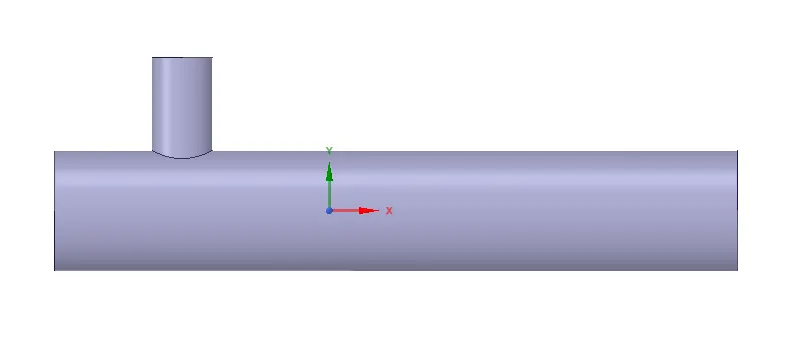
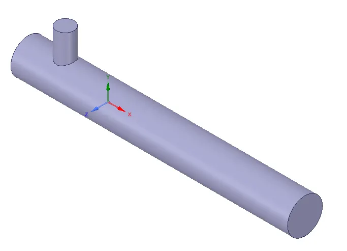
The CAD model is imported into the SpaceClaim to extract the flow volume field from the model. The extracted volume is
shown below:
Mesh
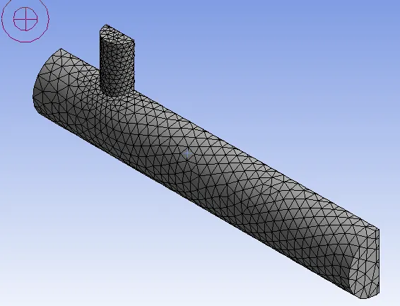
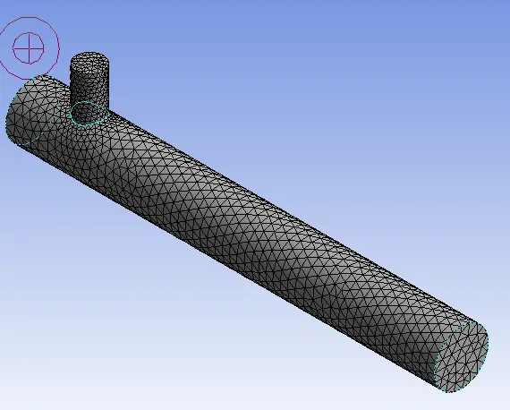
The boundary names are applied in this section and a mesh is generated.
Setup
In this section, we apply different boundary conditions like inlet, outlet boundary conditions. Turbulence models are set up like
K-epsilon or K- omega for solving the turbulent mixing of air. The number of iterations is set in this section.
CFD-Post
Post-processing is carried in this section in which different contours are setup to visualize the properties (such as Temperature,
Velocity etc.) for which simulation is run.
CASE 1 - SHORT TEE
a) For inlet velocity of 3m/s and momentum ratio of 2
A mesh element metric that identifies the quality of the mesh is employed and it can be seen that the elements of the lowest
the quality employed is minimal. Most of the elements have quality in the range of 0.7 to 1. Hence the mesh is of acceptable
quality
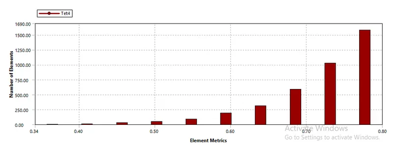
MESH of size = 0.001m
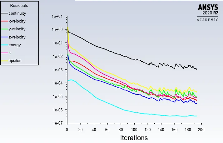
Residual Plot:
12728
Standard-Deviation of Temperature Plot:
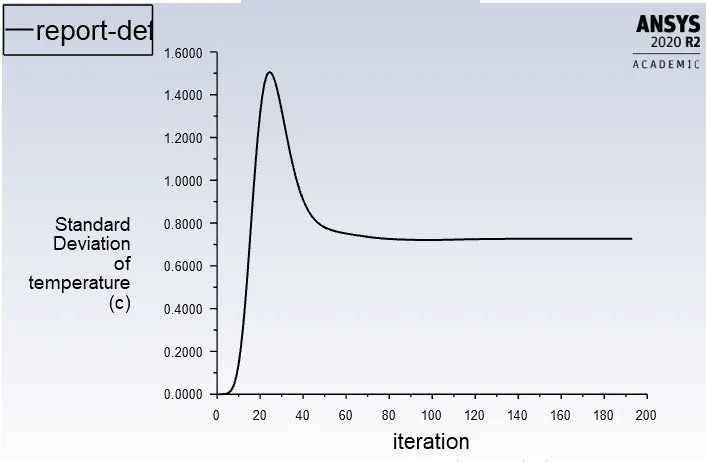
AWA of Temperature Plot:
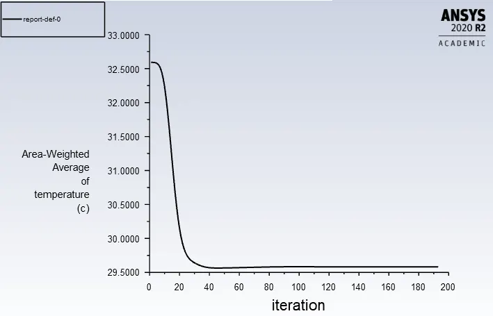
Contours
1) Temperature:
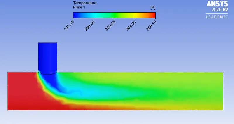
2) Velocity:
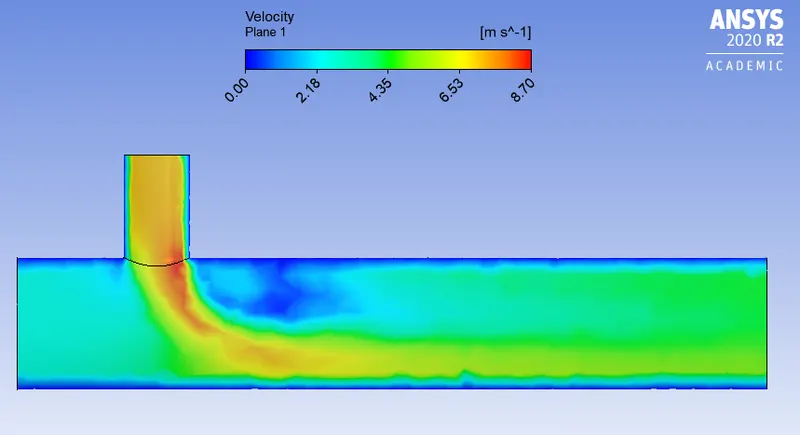
For inlet velocity of 3m/s and momentum ratio of 4
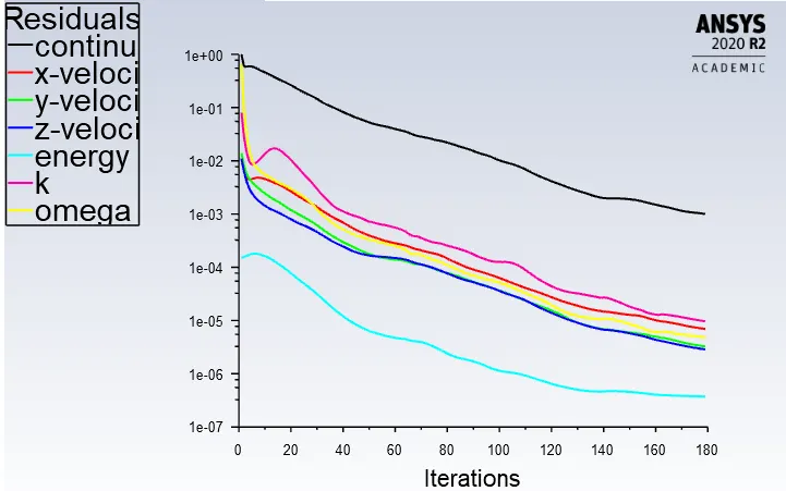
Residual plot:
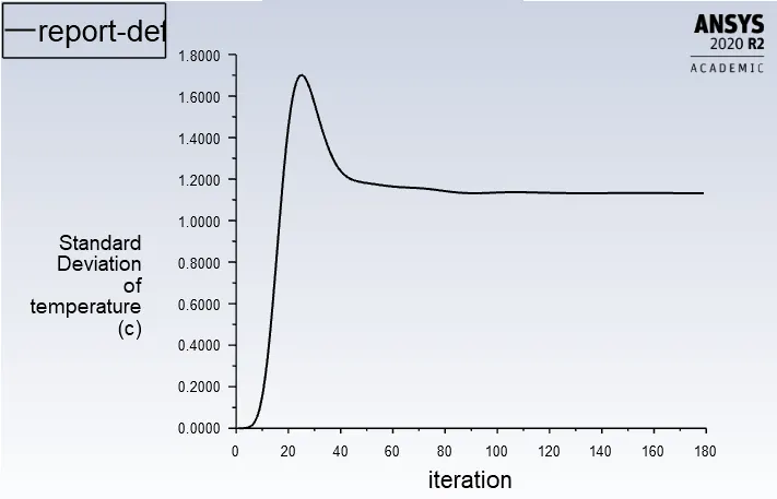
Standard-Deviation of Temperature Plot
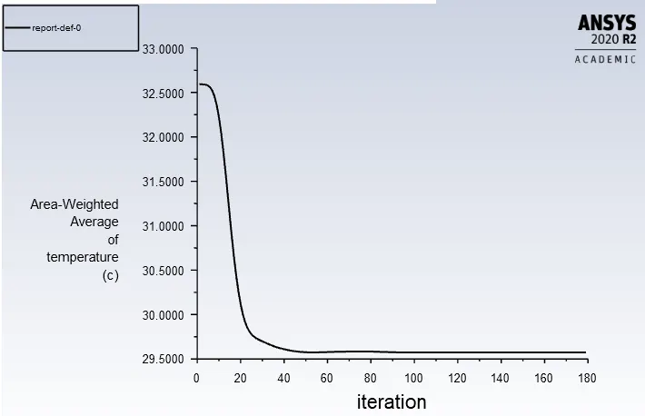
AWA of Temperature Plot:
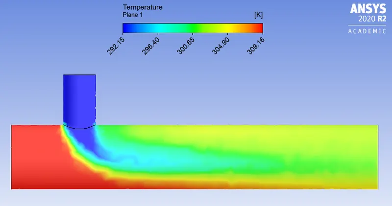
Contours:
1) Temperature:
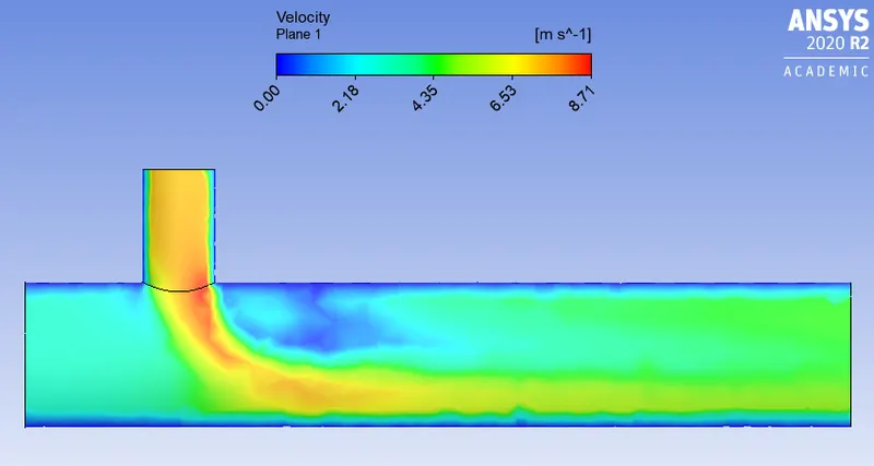
2) Velocity
CASE 2 - LONG TEE
a) For inlet velocity of 3m/s and momentum ratio of 2
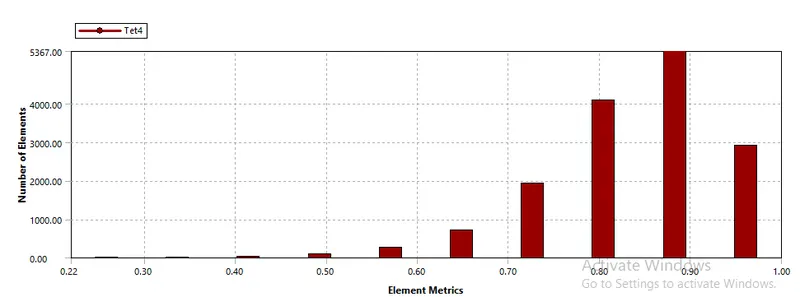
A mesh element metric that identifies the quality of the mesh is employed and it can be seen that the elements of the lowest
the quality employed is minimal. Most of the elements have quality in the range of 0.7 to 1. Hence the mesh is of acceptable
quality.
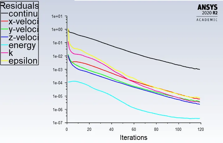
MESH of size = 0.001m
15368
Residual:
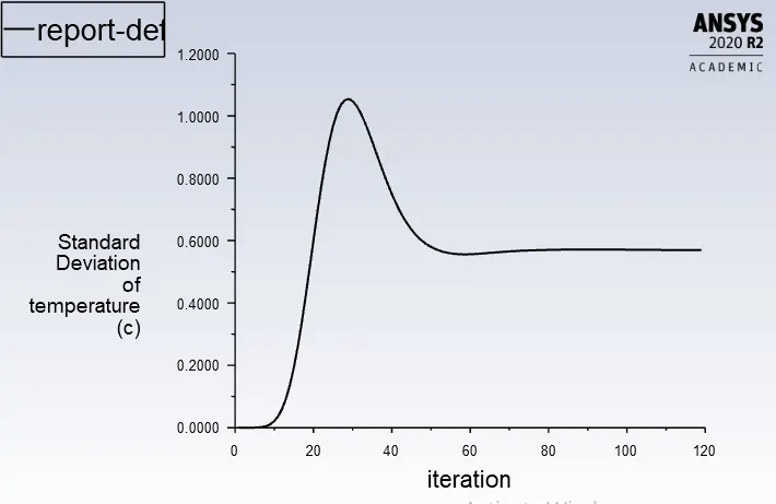
Standard Deviation:
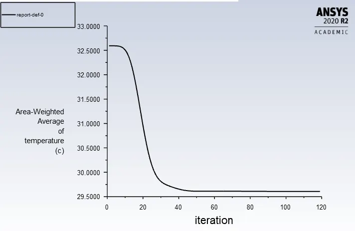
AWA of Temperature:
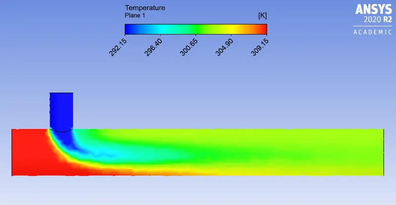
Contour
1) Temperature:
2) Velocity:
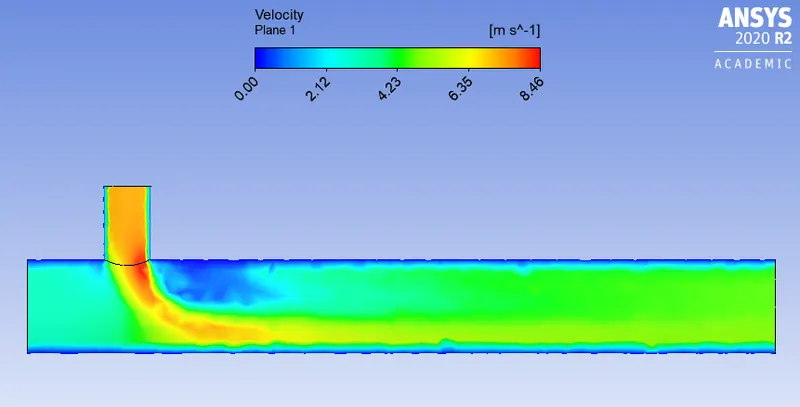
Comparison of all cases:
Case Cell Count AWA of Temperature(c) Number of Iteration
Short Tee- Momentum Ratio 2 12728 32.29 250
Short Tee- Momentum Ratio 4 12728 29.57 250
Long Tee- Momentum Ratio 2 15368 32.40 250
CONCLUSION:
1. As seen in Case 1-A and Case 1-B, the temperature at the outlet drops down significantly due to the high velocity of cold air
from the inlet. This is possible due to turbulent mixing at the tee joint between hot air and cold air because of the high velocity
of cold air, which is not possible in the case of low-velocity cold air.
2.The temperature contour at the outlet for short tee cases shows that some of the high-temperature flow sips through without
properly mixing with the flow. Whereas, in the temperature contour of long tee cases, the high temperatures flow thoroughly
mixes with the rest of the flow.
3. Therefore, we can recommend using the long tee and high-velocity inlet for application. This is because we have a low
standard derivation in the case of a long tee compared to the short tee for both momentum ratios.
4. K-epsilon model predicts well far from boundaries (wall) and K- omega model predicts well near the wall. Even though it
depends on Y+. Therefore, the K-epsilon model is majority used for free flow away from the wall and as in this project, there is no
dealing with the wall of the mixing tee for change in temperature along the length of it, so the K-epsilon model was chosen for
further simulations.