Week 1:- Introduction to BiW and Fixtures Challenge
AUTOMOTIVE BIW FIXTURE DESIGN USING CATIA V5
Q.1)
BODY IN WHITE
Body-in-white (BIW) is the name given to a car body’s sheet when all its components—barring moving parts (e.g., hoods, fenders, etc.), trims (e.g., glass, seats, etc.), or chassis subassemblies—have been welded together.
Usually, BIW constitutes about 27% of a car’s curb weight, and remains the key determinant of how the car will perform. BIW can be made into two structures: the more common monocoque structure where all body members are carrying load with chassis in-built with BIW and are integrated with each other, and the body-on frame structure where the frame is the main load carrying member.
The Car Bodies are categorized into two types, based on its initial construction, as shown below,
- Body-on-Frame.
- Monocoque / Uni-Body.
1.1 Body-on-Frame
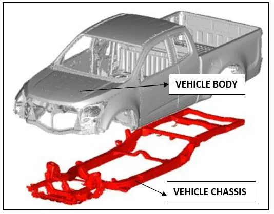
The Body on Frame was the simple construction of car, which had two segregations, one is the chassis, which forms the lower body of car, which has the engine and drivetrain and the upper body comprises of the covering laid down in support of chassis, which has the pre-assembled side doors, back doors and interiors.
- Although, Body-on-frame, was simple in construction, but had many drawbacks, like heavier weight, Lower fuel economy rating, Rougher rides on normal roads etc.
1.2 Monocoque / Uni-Body
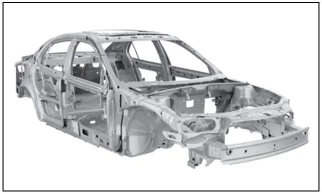
Monocoque / Uni-Body is a type of body construction in which the body of the vehicle, its floor plan and chassis form a single structure. Such a design is generally lighter and more rigid than a vehicle having a separate body and frame.
- Uni-Body cars have better fuel economy, Smoother ride quality, and stronger internal frame construction.
- Un-Body cars has More expensive design and manufacturing costs and expensive to repair.
BIW PARTS
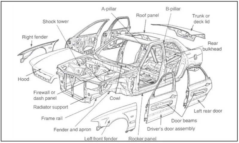
BIW structure is categorized into following parts: -
- Under body Structure.
- Front End Structure.
- Body Side Structure.
- Closures.
- Roof.
An Under Body Structure:-
- Dash panel-provides partition b/w engine and the driver cabin.
- FRT floor - provides base for seats.
- Raiser - connects front floor to rear floor by providing level difference.
- Rear floor - floor on the rear of the car and provides partition from ground and base for rear seats
- Rear wheel house
Front End Structure : -
- Plenum Panel- a chamber located b/w the throttle body and runners of the intake manifold.
- FRT wheel house (Fender)- is an encasement around the frt wheel.
- Wing panel - outer most side panel in the front
- Cowl -portion of the body bounded by the front fenders, the base of the windshield, and the rear edge of the hood.
- Upper tie bar -upper panel in front connecting the two sides of front structure.
- Lower tie bar- lower panel in front connecting the two sides of front structure.
Body side Structure:-
- pillar - front most support to the roof
- pillar - second support to the roof
- C/D pillar - is rear most support to roof in case of two row seating system, it will be third one.
- D - is the fourth support usually rear side of quarter panel.
- Ring panel - a structure panel connecting the rear and front portion.
- Quarter panel - rear most panel of a body side structure.
- Drip rails / Gutters- an exposed channel applied to the roof over the side
- windows to direct water away from the windows.
Closures :-
- All doors
- Hoods/Bonnet -a hinged panel providing access to the engine compartment.
Roof Structure:-
- Roof
- Headers - structural member above the windshield at juncture with the forward edge of the roof panel.
- Bows
Q.2)
BIW NOMENCLATURE
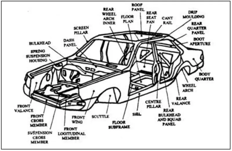
BIW nomenclature is the system of naming or terming the parts / components which forms the Basic construction of the vehicle inner skeleton.
The naming differs from country to country, But as to maintain the standard practice all over the world, we have considered here the terming/naming of BIW parts / components done between the country UK and US.
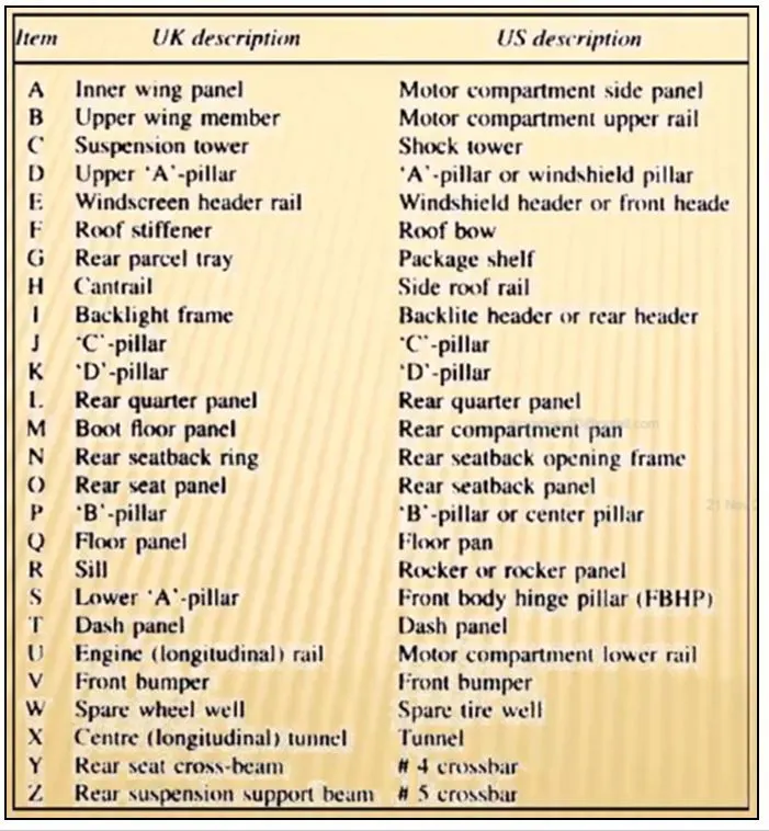
In the above table, you can find that, the Item – A, B, C, E, F, G, H..etc, have different names in UK and US description.
Whereas, Item-J,K, L, Tand V have same names in UK and US description.
Q.3)
FIXTURE AND ITS TYPES
FIXTURE
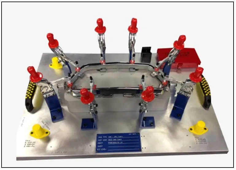
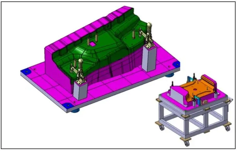
A fixture is a work-holding or support device used in the manufacturing industry. Fixtures are used to securely locate (position in a specific location or orientation) and support the work, ensuring that all parts produced using the fixture will maintain conformity and interchangeability.
Using a fixture improves the economy of production by allowing smooth operation and quick transition from part to part, reducing the requirement for skilled labor by simplifying how workpieces are mounted, and increasing conformity across a production run.
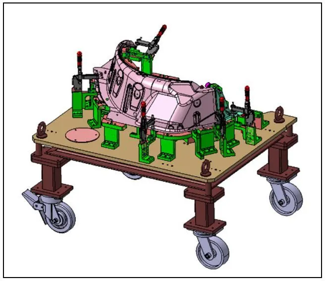
The above drawing is of a Automobile fixture, which has held the part of the vehicle with the help of clamping unit arrangements.
As the production of Automobile comes under continuous / mass production category. The fixture is created has a standard platform to perform the manufacturing related activities for an individual part of the vehicle.
In general, fixture is a holding device which holds the workpiece to be processed. In general fixtures are designed using 3-2-1 principle. Further, fixture should firmly hold the work piece without causing vibrations, distortions, stresses in the workpiece and also fixture should not disturb or interfere the processing of the workpiece.
TYPES OF FIXTURE
- Production Fixture.
- Pre-production operation fixtures (PPO).
- Checking fixtures.
- PRODUCTION FIXTURE
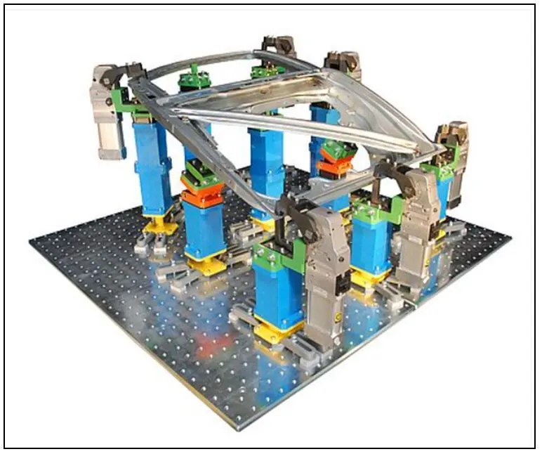
This fixture is used for mass production It requires high consistency through its operation to maintain the geometry of the parts so the material used is well tested for hardness & aesthetics. The quality for maintaining the dimensions & tolerances are also checked.
- PRE-PRODUCTION OPERATION FIXTURES (PPO)
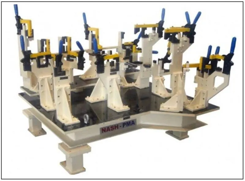
These fixtures are designed as a prototype fixture to check the feasibility of initial batch production & to check which things need to be improved before starting.
These fixtures can be taken as the base fixtures which sets the benchmark & criteria which help us to rectify the errors that we could get from preproduction operation fixtures.
In Pre-production fixture there are many manual operations are involved, many engineers & quality-related persons are required. It has a large cycle time as compared to production fixtures. It requires lots of time & expensive in nature.
- CHECKING FIXTURES
As the name suggests these fixtures are used for checking operations like welding gluing or hemming that are carried out in these fixtures.
The gauges are used in these fixtures to get the dimensions & the tolerances part having & the data is compared with the designed dimensions to check whether the part is ok or not.
The geometry of the welded parts is also checked in these fixtures to ensure the parts maintain the required dimensions & geometry.
Q.4)
BASIC PRINCIPLES OF FIXTURE DESIGN
The question of properly locating, supporting and clamping the work is important since the overall accuracy is dependent primarily on the accuracy with which the workpiece is consistently located within the fixture.
There must be no movement of the work during machining. Locating refers to the establishment of a proper relationship between the workpiece and the fixture.
- Principle of Location
In order to study the complete location of a workpiece within a fixture, let us consider a workpiece in air as shown in below figure. The workpiece is assumed to have true and flat faces. In state of freedom, it may move in either of the two opposed directions along three mutually perpendicular axes – XX, YY and ZZ.
These six movements are called the “movements of translation”. Also, the workpiece rotate in either of two opposed directions around each axis, clockwise and anti-clockwise. These movements are called “rotational movements”.
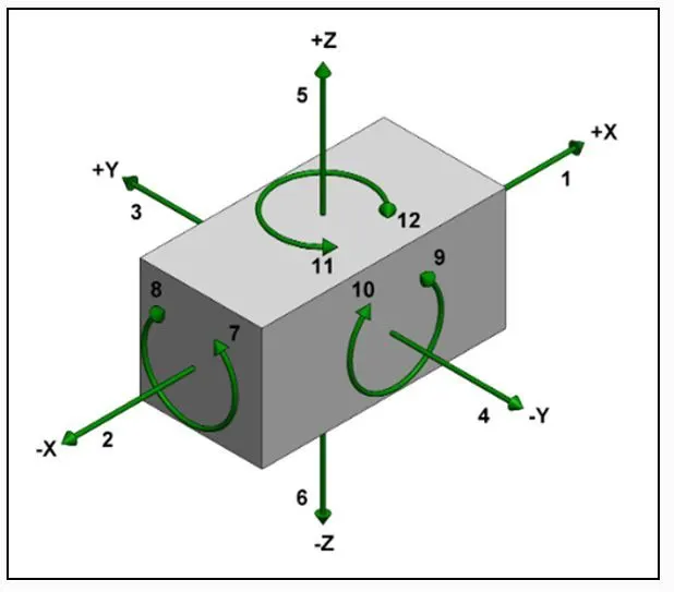
For any body there are total 12 Degrees of Freedom, as shown in above diagram,
- 6 Translational Degrees of Freedom
+X, -X, +Y, -Y, +Z, -Z
- 6 Rotational Degrees of Freedom
- Clockwise around X axis (CROT-X)
- Anticlockwise around X axis (ACROT-X)
- Clockwise around Y axis (CROT-Y)
- Anticlockwise around Y axis (ACROT-Y)
- Clockwise around Z axis (CROT-2)
- Anticlockwise around Z axis (ACROT-2)
We must fix all the 12 Degrees of Freedom in order to locate the workpieces in the fixture.
Many dedicated fixtures for prismatic parts are designed using the “3-2-1” locating principle.
- The “3” in 3-2-1 refers to 3 locators (passive fixture elements) on the primary locating/datum surface.
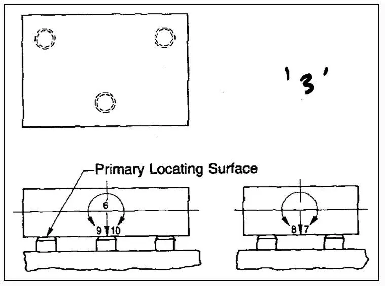
This restricts the axial movement downward and 4 radial movements. Together the three locators restricts five degree of freedom.
- The “2” in 3-2-1 refers to 2 locators on the secondary locating/datum surface.
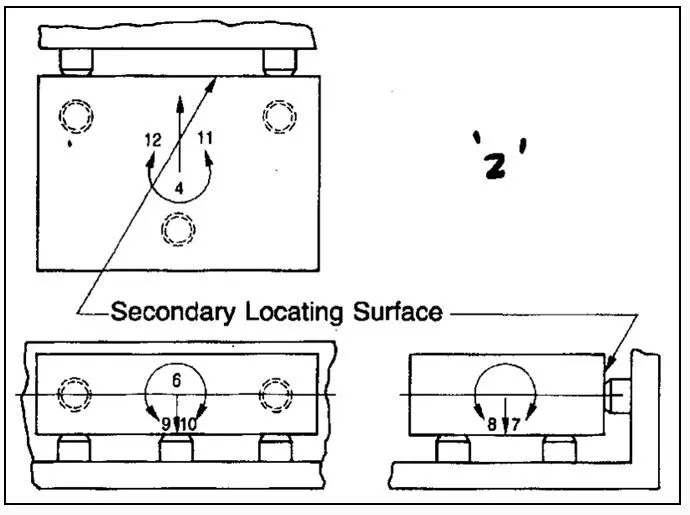
This restricts one axial movement and two radial movements. Together the two additional locators restricts three more degree of freedom.
- The “1” in 3-2-1 refers to 1 locator on the tertiary locating/datum surface.
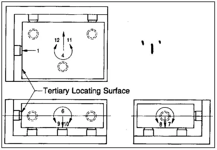
The single locator pin restricts the last degree of freedom.
Q.5)
TYPES OF BIW STATIONS
An assembly line is a process in which car panel/car body parts are joined as the semi-finished assembly moves from one station to another station until the final product is produced.
In the process of joining in assembly line, panels are moved from one section to another sections. Those sections are called Station.
In BIW fixture designing we have various stations which are used to locate the panels so that joining processes can be done.
Some of these stations are:
- Geo Station.
- Re-spot Station.
- Hemming Station.
- Checking Station.
- Gripper Station.
- Stands.
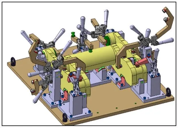
- GEO-STATION
In this station geometry of two parts are fixed, it can be either using welding or riveting. In this station precision and geometry of the finished product is defined Locating pins have closer tolerance of 0/-0.15.
Suppose the hole dia. of panel is 16mm then the pin dia. minimum can be 15.85.
Diameter of locating pins should be lesser than the panel hole dia. So, Tolerance in locating pin is given in negative value.
- RESPOT STATION:
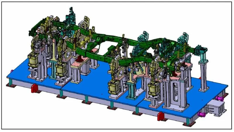
Once product comes out of the Geo-Station, there are few left out spots where spot welding or riveting is to be done. The next station where this product is moved is called Re-spot station.
The left out spots may be the due to clamp plan, cycle time, robot reach ability or any other various reasons.
In this station pins have tolerance up to 0/-0.28.
- HEMMING STATION:
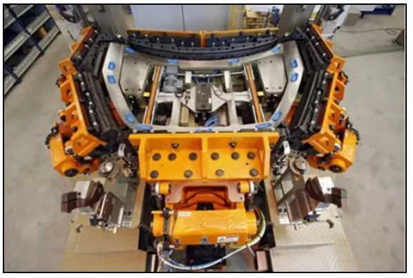
In the hemming station, the process of bending/folding the flange of the outer panel over the inner one is carried out. The accuracy of the operation affects significantly the appearance of the car’s outer surfaces and is therefore a critical factor in the final quality of a finished vehicle.
Hemming is performed in order to:
- Achieve a better final geometry in the vehicle´s part
- Add resistance and rigidity to the part
- Allow a safe handling of the part
- CHECKING STATION:
Checking Station is used to check the automotive part or assembly to ensure all the coordinated, relative dimensions and positions are as per tolerance. It can be classified as follows:
- Gauge type checking fixture is where the work piece is held and various gauges are
introduced to ensure the dimensions and repeatability. - Fixed type checking fixture is where the work piece is fixed using clamps and pins and the Coordinate Measuring Machine is used to measure the coordinates of different points of the panel and compare it with the nominal value and give its report to rectify any errors.
- Automated checking fixture is where the automated setting are being done through
sensors, PLCs, switches etc, to give a signal in case of any irregularities which can be
As it is expensive, it is not widely used.
- GRIPPER STATION:
A gripper is a device that enables the holding of an object to be manipulated. The easier way to describe a gripper is to think of the human hand.
Just like a hand, a gripper enables the holding, tightening, handling, and releasing of an object. A gripper is just one component of an automated system. A gripper can be attached to a robot or it can be part of a fixed automation system.
Types of Grippers
- Material Handle Grippers
Material Handling Grippers are designed for handling the car panel from one tool to other tool.
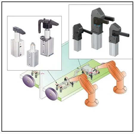
- Process Gripper
Process Gripper are designed for handling the car panel from one to other tool (station), and in addition to that it undergoes process like pedestal welding, pedestal riveting, gluing and sealing etc.
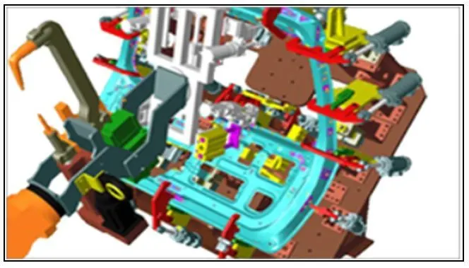
- Combo Gripper
Combo gripper is similar to process gripper, where there is a combination of weld gun at another side of the gripper for welding.
Combo gripper can do multi tasking (both process like gluing and material handling held at same time in Combo gripper).
COMBO GRIPPER = GRIPPER + WELD GUN
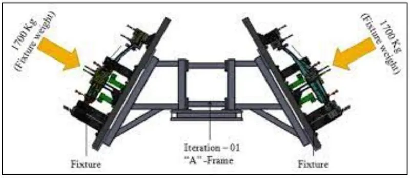
DUAL GRIPPER:
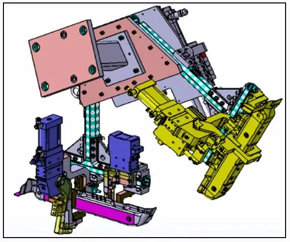
Dual gripper are designed for handling the car panel from one tool (station) to other tool (station) with two sided gripper.
As shown in the below figure below the gripper will be on both side, holding the panel/part/component.
DUAL GRIPPER = GRIPPER + GRIPPER
- STANDS:
Stands are use to hold the components like Glue gun,sealer gun,weld gun etc., where these stands are fixed to the floor/ground permanently. The types of stands are as follows,
- Pedestal stands.
- Gluing stands/Sealer stand.
- Docking stands.
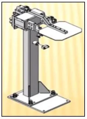
PEDESTAL STAND
A pedestal Stand is a stand used to carry the tool / equipment for performing a particular function.
Weld gun is mounted to a fixed stand, which is grounted to the floor permanently, where the process gripper carries he car panel / part to weld the spot with this fixed weld gun.
GLUING STANDS/SEALER STAND
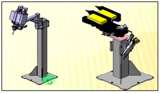
Gluing / sealer stand is the stand which is used to glue the automobile parts / components, when placed in the dedicated fixture.
The Gluing stand is fixed to the platform of the main fixture block, whenever its requirement comes for.
DOCKING STAND
Docking Stand are used for placing welding gun or gripper or tool, while the fixtures are engaged in multi-operations to avoid excessive payloads while material handling.
Docking Stand is a station which contributes in sharing the load from the main fixture block.
MISCELLANEOUS STANDS
The Misc. Stands is used to carry out the supportive activities of the automobile parts / components.
- Curing Stand
Once the Gluing of automobile parts are completed, then the glued area on that part has to undergo a curing process.
The Curing process helps to strengthen the bond made between the glued parts. Hence, the Curing Stand holds the glued assembly to undergo curing process.
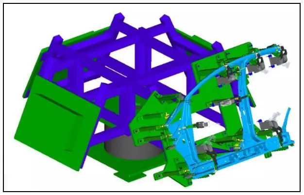
- Buffer Stand
Buffer Stand acts as a station to hold the finished / semi-finished part assembly, when the subsequent stage / process is busy.
The Buffer Stand also comes in fixed state or moveable type, for easy movement from one process station to another process station.
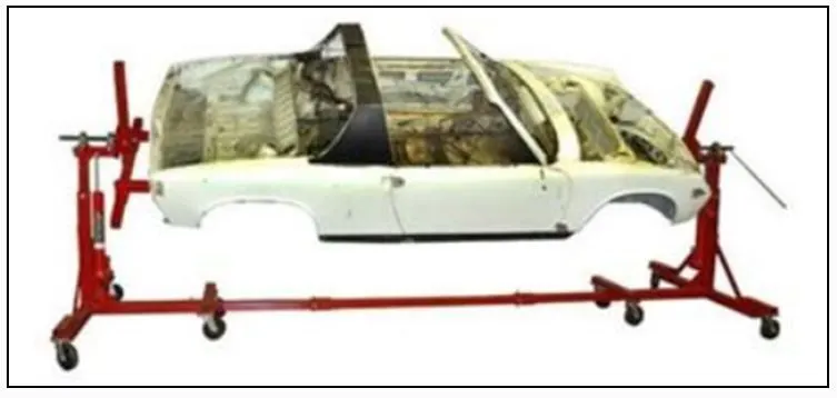
- Take out Trolleys
The Take-out trolley, is similar to buffer stand, which comes with wheels at the bottom of the stand.
The Take-out trolley, consists of jig arrangement to hold the automobile part, and to carry from one station to another station.
- Conveyors
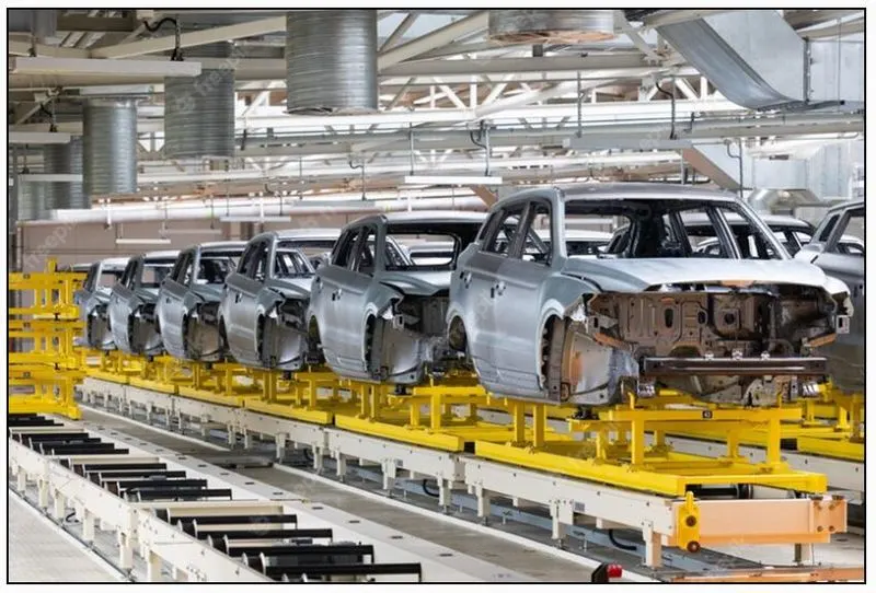
Conveyors are automated material handling systems.
Conveyors helps to handle the material / part / component to reach its next station either in forward / Reverse direction based on the operations to be carried out on it.
Q.6)
BASIC TERMINOLOGIES USED IN BIW FIXTURE
NC / MYLARS / FINGERS
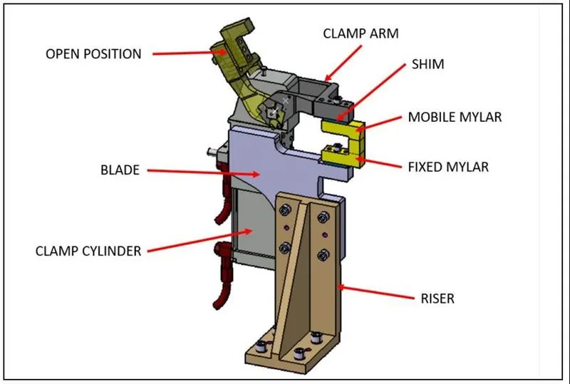
Mylars are the clamping device used to hold the Automobile panels.
Mylars are mounted on any block or plate with Shimming, So that height of mylar can be adjusted accordingly at the assembly level.
In the above diagram, two types of Mylars are shown, one is Mobile Mylar and another one is the Fixed Mylar.
PLP (PRINCIPAL LOCATING POINTS)
PLP’s are points present in the car panels or surface parts, where holes are present.
The Pins present in the fixture is dedicated for the respective point on the car panel, where the holes are present for placing the panel.
BLADE
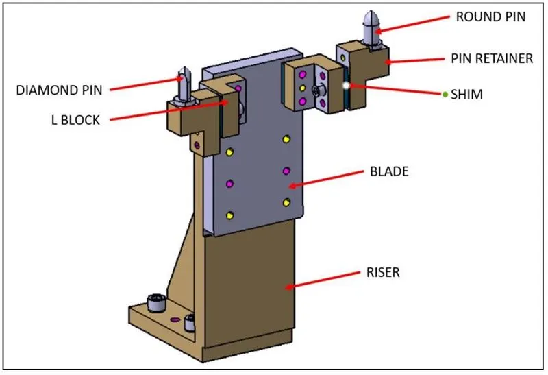
Blade is generally attached to the Riser.
The Blade consists of dedicated holes for making the necessary height arrangement of the tool with the support of Riser.
RISERS
Risers are made with different heights to carry the panels / surface parts by the support of Blades.
Risers are generally fixed to the base block of fixture unit. There are two types of Risers in general,
- L-type Riser.
- Square Tube Riser.
SHIMS
Shims are present in the MYLARS, to compensate the clamping forces, while clamping the panel/ surface parts.
Shim is a set of thin plates (2 mm, 1mm, 0.5 mm, 0.25mm) that are used to adjust the gap or used for a better fit. Shimming can be of thickness 5mm, 8mm, or 10mm. in case no proper fitting between mylar and Panel due to manufacturing errors then this error can be removed using shims. Shims are placed in the carline position so that gap can be adjusted in the required direction like X, Y, or Z.
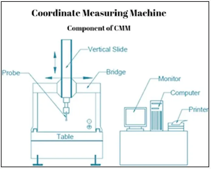
CO-ORDINATE MEASURING MACHINE
A coordinate measuring machine, also known as a CMM, is a piece of equipment that measures the geometries of physical objects. CMMs using a probing system to detect discreet points on the surfaces of objects.
CMMs are most often used to test a part or assemble to determine whether or not it respects the original design intent. CMMs are integrated within quality assurance or quality control workflows to check the dimensions of manufactured components to prevent or resolve quality issues.
The advantages of using CMMs over manual inspections or checks performed with conventional metrology instruments, such as micrometers and height gauges, are: accuracy, speed and the reduction of human error.
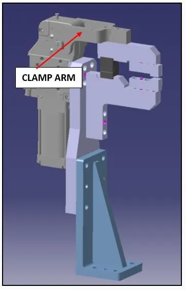
CLAMP ARM
The Purpose of the Clamp Arm is to exert a pressure to press a workpiece / panel / surface parts against the locating surfaces, to avoid displacement, while performing manufacturing operations.
The Clamp arm should be designed to deliver the required clamping force when operated by smallest force expected.
REED SWITCHES
- These are electric parts used in automated fixtures which run through PLC programming.
- These electrical switches are operated by an applied magnetic field.
- Reed switches are placed in the sides of the pneumatic cylinders to confirm the clamping of panels.
CLASS-A SURFACE
The Outer surface of the panels / surface parts are called as the ‘CLASS-A’ surface.
While designing the fixture to the skin surface the clamping material should be soft, so that it could not able to left any impression or dent over the skin. generally, nylon or PU material is used for clamping purposes.
PIVOT
Pivot is the axis about which the clamp arm rotates.
The pivots provides a swivel action for clamp arm to hold and release the panel / workpiece.