Week 1:- Introduction to BiW and Fixtures Challenge
1.BIW
BIW stands for Body In White.
BIW refers to the welded sheet metal components which from the vechicles structure to which the other components will be married i.e engines, chasis, interior and exterior trims.
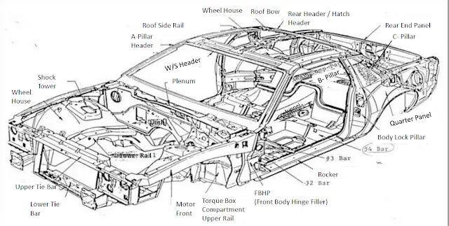
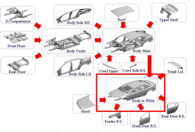
Parts
1. Body Sides
Body side outer
Body side inner
2.Under Body
Front end under frame (Engine Compartment)
Main Floor
Rear end under frame
3.Closures
Front Door
Rear Door
Hood
Deck Lid
4.Roof
Roof Inner
Roof Outer
5.Fender
Components
2.BIW Nomenclature
- Monocoque Body Structure
In Monocoque body, chasis is in built in BIW itself and there is no seperate chassis. Wheels are directly mounted to the BIW which the help of the suspension system.
- Frame mounted Body Structure
In Frame Mounted Body, body is mounted on the seperate chassis/frame and the wheels are mounted on the chassis and not to the body.
3.Fixture
Fixture is a device which holds the work piece to be processed(welded) by using 3-2-1 priciple.
Types
- Production Fixtures
- Pre Production Operation Fixtures
- Checking Fixtures
4.Priciple of Fixture Design
Fixture design using 3-2-1 principle is used to lock all six degree of freedom.
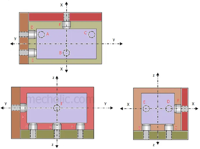
The 3-2-1 principle is a Component holding principle where three pins are located on the 1st principle plane, i.e. either XY, YZ, ZX.
And two pins are located on the 2nd plane which is perpendicular to the 1st plane, and at last one pin on the plane which is mutually perpendicular to the 1st and 2nd planes.
By using this method Componet can be arrested in all six degrees of freedom.
5.Types of BIW Stations
An assembly line is a process in which car panel/car body parts are joined as the semi finished assembly moves from one station to another station until the final product is produced.
In the process of joining in assembly line , panels are moved from one section to another sections.Those sections are called Station.
In BIW fixture designing we have various stations which are used to locate the panels so that joining processes can be done.
Some of these stations are:
- Geo Station
- Respot Station
- Pedestal Weld/Rivet
- Loading Station
- Buffer Station
- Marriage station
- Sealing station
- Curing station
In this station geometry of two parts are fixed. it can be either using welding or riveting . In this station precision and geomatry of the finished product is defined Locating pins have closer tolerence of 0/-0.15.
Suppose the hole dia of panel is 16mm then the pin dia minimum can be 15.85.
Diameter of locating pins should be lesser than the panel hole dia. So Tolrence in locating pin is given in negative value.
Once product comes out of the Geo Station and there are left out spots where spot welding or riveting is to be done. then it is moved to another station , that station is called Re-spot station.
These left out spots may be the due to clamp plan, cycle time,robot reach ability or any other various reasons.
In this station pins ahve tolrence upto 0/-0.28.
In this station , Pedestal gun is mounted on a tool and panel is manipulated manually or by robot to weld the panels.
Pedestal station is generally a Re spot station.
Re spot station and Pedestal station, both perform same kind of operation . but to decide whether to go for pedestal or a re-spot station some parameters needs to consider like cycle time, floor space, no. of welds, clamp plan, or size of the panel.
This station is used for loading of panel and same station is used to change the orientation of the if it is required in the upcomin station.
Sometime this station is used when Robots are unable to transfer panel from one station to another.
This station is used to make the balance between the process.
Some stations carry out procees in lesser time as compared to their respective stations.In that case panels can be stored in one sation so that assembly line process remains smooth.
In this station Sealant application is carried out.This process can be carried out manually or by using robots. Sealer is used in between two panels so that panels do not flatter due to friction.
In this Station inner and outer panels are joined. In this station to avoid the imprssion on the outer panel(A class surface), copper strips are used in betweenn the weld tip and A-class surface.
In this Station product recieved after sealing application, is kept idle at ambient temperature, which allows sealent to get dry with better bonding between the panel.
6.BIW Fixture Termilogies
- NC/Mylares/Fingers
- Clamp
- Sensor
- Bladers
- Risers
- Pivot
- A skin Surface
- Name Plate
- Units
- Number Plate
- Shims
- Clamp Arm
- Reed Switches
- Rough Locators
- Princple Localting Point
- CMM
- Hardwares
Shim is a set of thin plates (2 mm, 1mm, 0.5 mm, 0.25mm) that are used to adjust the gap or used for a better fit. Shimming can be of thickness 5mm, 8mm, or 10mm. in case no proper fitting between mylar and Panel due to manufacturing errors then this error can be removed using shims. Shims are placed in the carline position so that gap can be adjusted in the required direction like X, Y, or Z.
There are three types of shimming. These are one-way, two-way, and three-way shimming.
Number of shimming depends upon the NC cut angle and PIN angle with the car line.
If NC cut is less than 15 deg then mylar will have one-way shimming.
If NC cut is more than 15 deg in one direction then mylar will have a 2-way direction shimming
If NC has more than 15 deg angle in two directions then mylar will have 3-way directional shimming.
But in the case of pins, this case is a bit different. If the pin is on the angle with respect to the carline and that angle is more is not more than 15 deg then the pin will have 2-way directional shimming, if Pin’s angle is more than 15 deg in any direction then 3 shimming will be used.
MYLAR :
MYLAR is one kind of block that touches the panel and holds or clamps the panel. Mylars are always designed in CAR LINE. Mylar is also called NC(Numerically Controlled)Block. Mylars are mounted on any block or plate with Shimming, So that height of mylar can be adjusted accordingly at the assembly level. For ‘A’ class surfaces Nylon mylars are used. So that surface can be saved from scratches.
Shimming can be 1 directional, 2 directional, or 3 directional as per the NC cut.
PIN:
Pins are used to locking the rotational movement of the panel. Generally there two types of Pins, one is Round Pin and another one is a Diamond pin. We use two and three-directional shimming for pins as per the angle of the pin w.r.t. the carline. In some cases, we use a collared pin, when the pin is supposed to support the panel as well. For this kind of pin, we provide 3 way shimming irrespective of pin angle to the carline.
BLADE :
The plate which connects Riser to the Clamp cylinder is named Blade. This plate plays an important role in building the unit. The plate can be of any shape. But we need to keep in mind that the plate should be as compact as possible.
L BLOCK :
A plate shaped as L is called an L block. This part is used as a connection between mylar and Blade. Generally, L blocks are used to provide shimming. It is not necessary that L blocks are only used for shimming, its uses changes as per the requirements, At some places, it is used just to connect one part to another. Similar to the L block one more block is used which is in the shape of T. So this block is called a T Block.
PIN BLOCK :
Pin Block is also called Pin Retainer. This block holds the pin and restricts the rotational motion of the pin. Pin Block can be either manufactured one or Standard.
RISER :
The part which is mounted on the base plate and holds a clamp or pin cylinder on it, is called Riser. Riser can be Standard Part or manufactured part, it varies from project to project. A riser can be a Single part or welded part. Standard risers also have various shapes and sizes.
WELDMENT :
Weldment is the assembly of two or more parts that are joined by welding. To make a weldment it is the thumb rule to have a 5 mm overlay on each other plates so that space can be provided for welding. A weldment can be of any size and any number of plates.