Week 1:- Introduction to BiW and Fixtures Challenge
What is BIW & define its parts?
BIW- In the Automotive Industry BIW (Body in White) is the common terminology used to mention the car sheet metal welded structure (body shell).
- Monocoque Body structure.
- Frame Mounted Body structure.
1.MONOCOQUE BODY STRUCTURE:
In this type of Body structure, Chasis is in built in the BIW itself and there is no seperate chasis. Wheels are directly mounted to the BIW with the help of a suspension system.
2. FRAME-MOUNTED BODY STRUCTURE:
In this type of body structure, Body is mounted on separate chasis or frame & wheels are mounted on the chasis not to the body.
BIW PARTS:-
BIW structures can be divided into following sub-structures:
- Underbody structure.
- Front End Structure.
- Body side structure.
- Closures.
- Roof.
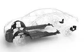
1) An Underbody Structure consists of the following major panels:
- Dash panel - Dash panel provides a partition between engine and the driver/passenger cabin inside car
- FRT Floor - provides a base for seats mounting and provides partition between transmission /propeller shaft/ground and the cabin.
- Riser- Riser connects Front floor to Rear Floor by providing a level difference
- Rear Floor- Rear Floor is the floor on the Rear of the car and provides a partition from ground also provide base for Rear seat mounting.
- Rear wheel house
2) Front end structure consists of following major panels:
- PLENUM Panel - Plenum is a chamber located between the throttle body and the runners of the intake manifold, used to distribute the intake charge evenly and enhance engine breathing.
- FRT wheel house/ Fender - FRT Wheel house or Fender is an encasement around the FRT wheel.
- Wing panel - Wing panel are the outer most side panel in the front.
- Cowl - Cowl is the portion of the body bounded by the front fenders, the base of the windshield, and the rear edge of the hood
- Upper tie bar- Upper tie bar is the upper panel in front connecting the two sides (RH/LH) of Front structure.
- Lower tie bar- Lower tie bar is the lower panel in front connecting the two sides (RH/LH) of Front structure.
3) BODY SIDE structure consists of following major panels:
- A-pillar- A-Pillar is the front most support to Roof.
- B-pillar- B-Pillar is the second support to the roof and situated on the locking side of the Front door.
- C/D pillars- C-Pillar is the Rear most support to roof in case of a two row seats car, OR third support to the roof. D-pillar is the forth support to the roof and usually on the rear side of quarter panel.
- Ring panel - Ring panel is a structure panel connecting the rear portion of the body to front, and constitutes a big part in side structure.
- Quarter panels- Quarter panel is rear most panel of a body side structure.
- Drip rails/Gutters- Drip rails/Gutters is an exposed channel applied to the roof over the side windows to direct water away from the windows and to cover structural welding.
4) Closures consists of following major panels:
- All Doors
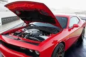
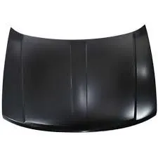
- Hood/Bonnet -Hood is a hinged panel providing access to the engine compartment.
5) Roof structure consists of following major panels:
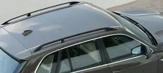
- Roof
- Headers- Header is the structural member above the windshield at the juncture with the forward edge of the roof panel.
- Bows- Those are used to support the roof.
Nomenclature is basically choosing names for thing. BIW have no. of parts in it. All parts have different names.
As automotive industry is spread worldwide. Every nation has its own language. So the same part in BIW have different name in its region.
For example, One component of BIW is called suspension tower in UK & same component called shock tower in U.S. Below fig show BIW nomenclature
BIW NOMENCLATURE:
- Hence from the definition of nomenclature we came to know that the terms/names applied to the BIW COMPONENTS is known as BIW NOMENCLATURE.
- The terms are standard but they differ in some countries.
- As automotive industries spread world wide, the terms and standards will be different for similar components.
- For example, One component of BIW is known as inner wing pannel in UK description otherside the same component of BIW is known as Motor compartment side panel in US description.
- Below I have been attached some common terms of BIW which differs from UK to US descriptions
BIW fixture type:
- Production Fixture – As name suggest this fixture is used for mass production. It is fixture on which car body get assemble & go to end customer. These types of fixture require high constancy through its operation to maintain geometry of parts. So material used for these types of fixture should be well tested as well as hardness level aesthetic. The quality in terms of dimension, tolerance should be met. These fixture need to maintain after certain period of time. The assembly & disassembly should be easy as low as possible. So maintenance person can easily access with saving time.
- Pre-production Fixture- It is generally defined as prototype fixture. It is designed to study feasibility of initial batch production to check which things are need to be improving before starting production. This fixture is base of production fixture in benchmark and criteria & helps us to rectify error. In preproduction operation fixture there will be more involvement of manual operations, engineer, and quality person. It has larger cycle time than production fixture. But won’t practice by designing preproduction fixture because it takes lots of time & cost. We have to maintain cost of car as low as possible so we directly go to production fixture by considering standards, checklist to maintain error free production.
- Checking Fixture- As name suggest this fixture is used for checking assembly which came out from geo fixture. Checking fixture are same as geo fixture except there are no operation done like welding, gluing or hemming. Instead of that we use different in built gauges or external gauges to check various dimension, gap, relative dimension, tolerance. These data is compared with data provided by designer or design team of that particular. The geometry of welded part also checked in this fixture to ensure part maintains the required dimension & geometry.
You know that any free body has a total of twelve degrees of freedom as below:
6 translational degrees of freedom**: +X, -X, +Y, -Y, +Z, -Z**
And 6 rotational degrees of freedom:
- Clockwise around X axis (CROT-X)
- Anticlockwise around X axis (ACROT-X)
- Clockwise around Y axis (CROT-Y)
- Anticlockwise around Y axis (ACROT-Y)
- Clockwise arothe und Z axis (CROT-Z)
- Anticlockwise another und Z axis (ACROT-Z)
You must fix althe l 12 degrees of freedom except for the three transitional degrees of freedom (-X, -,Y and -Z) in order to locate theworkpiecee in the fixture. So, 9 degrees ,of freedom of the workpiece the workpieces.
LOCATING PRINCIPLE
3-2-1 locating principle: Holding fixtures used in assembly operations often follow a 3-2-1 locating scheme to position parts. Under this scheme, three locators position a part in a primary plane or direction (e.g., high/low). Two locators then position the part in a secondry direction (e.g., in/out), leaving one locator for the tertiary direction (e.g., fore/aft). This approach fixes the part in 3-dimensional space and satisfies the six degrees of freedom constraint. Below fig. show 3-2-1 locating principle
5.Elaborate types of BIW Stations
BIW Station flow chart
A. TOOLS: A Tool is a fixture which consists of Number of units together to hold a car part in general.Types of tools are as follows,
- Geo Tool
- Respot Tool
- Marriage Tool
- Framer Tool etc.,
1.GEO TOOL:
- A Geo tool is a fixture in which the geometry of the panels which are welded together is defined accurately.
- The pin tolerance for a geo pin will be of closer tolerance i.e 0.15 in general.
- For example: consider panel hole size 20mm, then the pin dia should be 19.85mm.
- It is a veryprecise fixture.
- Pin should be in undersize compared to the hole.
2. RESPOT TOOL:
- It is a fixture in which the remaining weld spots which are not achieved geo tool are welded for the pre welded panel from the geo tool.
- The weld spot which has been done in this tool is only for rigid or stifness prpose.where the geometry of the panels are already controlled in Geo Tool.
- For example: consider panel hole size 20mm,then the pin should be 19.72mm.
- The pin tolerance for a respot pin will be of tolerance with -0.28 in general
3. MARRIAGE (OR) HEMMING TOOL:
- A Marriage Tool is a fixture in which the inner pannel assembly & outer pannel assembly are joined.
- Hemming in case of closure panels.
4. FRAMER TOOL:
- The station after marriage tool is the framer tool.
- In this tool roof will be attached from the output of the marriage tool.
- After roof is attached with the help of framer tool.A car will now form a frame so the name arise is framer tool.
5. CHECKING TOOL:
- As from name we understand this type of fixtures are used for the checking purpose of the part or assemblies.
- A checking fixture is used to check the automobile parts or assemblies, ensuring all the coordinates,relative dimensions & positions as per the tolerances
- A checking fixture can be a gauge type, fixed typed & automated checking fixture.
- A checking fixture is a tool where workpiece is hold & various measuring gauges are introduced to ensure the dimensions & repeatability.
B. GRIPPERS: A gripper is a device or a fixture which holds the car panel, and is fixed to manipulating end of a robot or an end effector also known as EOAT - End Of Arm Tooling.Gripper should be in less weight so it is made up of frame like structures. Types of grippers are as follows,
- Material Handling Gripper.
- Process Gripper.
- Combo Gripper.
- Dual Gripper.
1. MATERIAL HANDLING GRIPPER:
- Material Handling Gripper are designed for handling the car panel from one tool (station) to other tool (station).
2. PROCESS GRIPPER:
- As name suggests, this gripper are used to carryout soeme process like gluing,welding,riveting etc., in addition with matterial handling.
- In Process gripper, either material handling will be done or some specific process will be done.
- It can not do Multitasking (both process like gluing and material handling at one/same time cant be done in process gripper)
3. COMBO GRIPPER:
- Combo gripper are designed for handling the car panel from one tool (station) to other tool (station). Also with the combination of weld gun at another side of the gripper for welding.
- Combo gripper can do multi tasking (both process like gluing and material handling held at same time in Combo gripper).
- COMBO GRIPPER = GRIPPER + WELD GUN
Figure 8. Combo gripper
4. DUAL GRIPPER:
- Dual gripper are designed for handling the car panel from one tool (station) to other tool (station) with two sided gripper.
- As shown in the figure below the gripper will be on both side.
- DUAL GRIPPER = GRIPPER + GRIPPER
C. STANDS: Stands are use to hold the components like Glue gun,sealer gun,weld gun etc., where these stands are fixed to the floor/ground permanently. The types of stands are as follows,
- Pedestal stands.
- Gluing stands/Sealer stand.
- Docking stands.
- Dtae stamp stand.
1. PEDESTAL STANDS:
- Weld gun is mounted to a fixed stand which is grounted to the floor permanently,where the process gripper carries the car panel to weld the spot with this fixed weld gun.
Figure 10. Pedestal gun stand
Figure 11. Pedestal gun stand
2. GLUING & SEALER STAND:
- Gluing gun or sealer gun is fixed to a welded or standard stand which is grounted to the floor permanently.
Figure 12. Gluing & Sealer stand
3. DOCKING STAND:
- When robots are selected for multitasking purpose like material handling & welding, which cannot carry both due to some limitations (pay load capacity of the robot or space constraint) the robot will drop & pick the gripper or gun after completing the respective operation with the help of docking stand.
Figure 13. Docking stand
4. DATE STAMP STAND:
- The panel will get the date embossed on to it, with the date stamping device which is mounted on this date stamp stand.
Figure 14. Date stamp stand
D. MISCELLANEOUS: The types are as follows,
- Curing.
- Buffer stand/storage.
- Racks.
- Takeout trolleys.
- conveyors.
1. CURING:
- After gluing it needs some time to cool down or to get dry.
- So we hold/hang the assemblies on curing,then it will move the panel to other stations.
- During the moving time the glued sides will be get cooled.
2. BUFFER STAND/STORAGE:
- Buffer storage are very similar.It is used mainly for storage purpose.
- It has provide sections,where n-numbers of assemblies kept after the operations completed (aproxymately between 10 - 15) as per designed.
- And these assemblies can be moved together for inventory purpose.
- While the machine is under maintanance, the panels has to be kept in stock for future supplies as per the production details.So here the Buffer stand palys a vital role,where the panels are kept in the provided sections and moved to stores for inventory pupose in a easy way.
Figure 15. Buffer stand
3. RACKS:
- Racks are nothing but where the panels or sub-assemblies kept in their allocation area.
- The Rack must contain several details like part name, part no.,model name etc., for identification purpose. so that the parts can be taken from the rack easily.
- The rack as to be designed in such a way that the identification of parts would be made esay.
- The parts should be kept above or below where the details are engraved in the racks.So that by identifying the details the parts can be handled by the operator easily without any confussion which consume time and may affect the production capacity.
4. CONVEYORS:
- Conveyors are the rotating path which transports the parts to the next station which kept over it.
- Conveyors can be of belt or chain type.
- It will actualy consist of a pallet or fixture type structure,where the panel will be kept and moved to the other station.
- This process will be in keep on rotation or moving from one end to other end as shown in the figure below.
Figure 16. Conveyors
5. TAKE OUT TROLLEY:
- Take ou trolley is used to take the car panel out of the robotic working cell between the cycle for inspection purpose.
- It is used to take out some panels for inspection pupose to rectify the process is going right or not between the cycle.
Figure 17. Take out trolley
Figure 18. Take out trolley
Hence,the types of BIW stations are elobrated above.
6.What are the basic terminologies used in the BIW fixture?
BASIC TERMINOLOGIES USED IN BIW FIXTURES:
The basic terminologies used in BIW fixtures are,
- NC/Mylars/Fingers.
- PLP (Principle locating points).
- Blade.
- Raiser.
- Shims
- Rough Locators.
- Hardwares.
- CMM.
- UNITS.
- Number plates.
- Co - ordinate plates.
- Name plate.
- Clamp arm.
- Pivot.
- Class 'A' surface (or) Skin surface.
- Reed switches.
- Sensors. Very commonly used parts are Mylar, Pin, Blade, L Block, Pin Block, Riser, Weldment, etc.
MYLAR :
MYLAR is one kind of block that touches the panel and holds or clamps the panel. Mylars are always designed in CAR LINE. Mylar is also called NC(Numerically Controlled)Block. Mylars are mounted on any block or plate with Shimming, So that height of mylar can be adjusted accordingly at the assembly level. For ‘A’ class surfaces Nylon mylars are used. So that surface can be saved from scratches.
Shimming can be 1 directional, 2 directional, or 3 directional as per the NC cut.
PIN:
Pins are used to locking the rotational movement of the panel. Generally there two types of Pins, one is Round Pin and another one is a Diamond pin. We use two and three-directional shimming for pins as per the angle of the pin w.r.t. the carline. In some cases, we use a collared pin, when the pin is supposed to support the panel as well. For this kind of pin, we provide 3 way shimming irrespective of pin angle to the carline.
BLADE :
The plate which connects Riser to the Clamp cylinder is named Blade. This plate plays an important role in building the unit. The plate can be of any shape. But we need to keep in mind that the plate should be as compact as possible.
L BLOCK :
A plate shaped as L is called an L block. This part is used as a connection between mylar and Blade. Generally, L blocks are used to provide shimming. It is not necessary that L blocks are only used for shimming, its uses changes as per the requirements, At some places, it is used just to connect one part to another. Similar to the L block one more block is used which is in the shape of T. So this block is called a T Block.
PIN BLOCK :
Pin Block is also called Pin Retainer. This block holds the pin and restricts the rotational motion of the pin. Pin Block can be either manufactured one or Standard.
RISER :
The part which is mounted on the base plate and holds a clamp or pin cylinder on it, is called Riser. Riser can be Standard Part or manufactured part, it varies from project to project. A riser can be a Single part or welded part. Standard risers also have various shapes and sizes.
WELDMENT :
Weldment is the assembly of two or more parts that are joined by welding. To make a weldment it is the thumb rule to have a 5 mm overlay on each other plates so that space can be provided for welding. A weldment can be of any size and any number of plates.
In this there is a term used shim so what is shim
Shim is a set of thin plates (2 mm, 1mm, 0.5 mm, 0.25mm) that are used to adjust the gap or used for a better fit. Shimming can be of thickness 5mm, 8mm, or 10mm. in case no proper fitting between mylar and Panel due to manufacturing errors then this error can be removed using shims. Shims are placed in the carline position so that gap can be adjusted in the required direction like X, Y, or Z.
There are three types of shimming. These are one-way, two-way, and three-way shimming.
Number of shimming depends upon the NC cut angle and PIN angle with the car line.
If NC cut is less than 15 deg then mylar will have one-way shimming.
If NC cut is more than 15 deg in one direction then mylar will have a 2-way direction shimming
If NC has more than 15 deg angle in two directions then mylar will have 3-way directional shimming.
But in the case of pins, this case is a bit different. If the pin is on the angle with respect to the carline and that angle is more is not more than 15 deg then the pin will have 2-way directional shimming, if Pin’s angle is more than 15 deg in any direction then 3 shimming will be used.