Week 1:- Introduction to BiW and Fixtures Challenge
Body in white (BIW) is the stage in automobile manufacturing in which a car body's frame has been joined together, that is before painting and before the motor, chassis sub-assemblies, or trim (glass, door locks/handles, seats, upholstery, electronics, etc.) have been integrated into the structure.
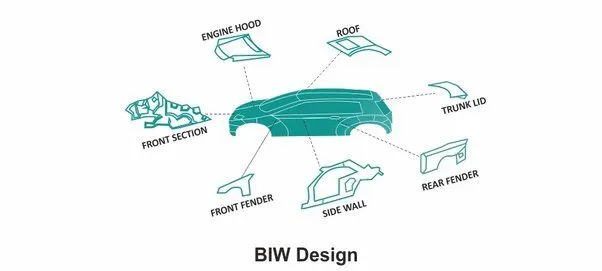
BIW parts are categorised as below
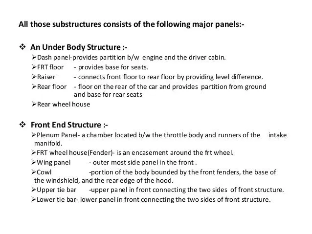
- Underbody structure
- Frond end structure
- Body side structure
- Closure
- Roof
2) What do you understand by BIW nomenclature?
- Nomenclature is basically choosing of names for things.BIW have no. of parts in it. All parts have differenent names.
- As the Automotive industry is spread worldwide. Every nation has its own language. So the same part of the BIW have different names in its region.
- For example, The one component of the BIW is called suspension tower in Uk & the same component is called shock tower in US.
3)What is fixture & its types?
A fixture is the device which holds the work piece to be processed (welded) by using 3-2-1 principle.
In BIW fixture, the fixtures are designed to hold no. of parts during welding. It is necessary to hold the parts at proper location to avoid the distortions & to maintain the required geometry of the parts.
Fig- shows BIW fixture
BIW fixture requirements
- It should prevent distortions in work piece during welding operation
- The clamping need to be light but firm means the clamping force should be able to maintain the part at its required position without damaging the part.
- Placement of clamping need to be clear of welding area.
- Fixture need to be quite stable & rigid to withstand the welding stresses.
- The fixture should maintain its consistancy to do defect free operations.
BIW fixture types-
- Production fixtures- This fixtures are used for mass production purpose. It requires high consistancy through its operation to maintain the geometry of the parts so the material used are well tested for the hardness & asthetics. The quality for maintaining the dimensions & tolerances are also checked. The production fixtures needs to easy for mainatainace purpose. The fixture needs some maintainance after completing no.of operations. The time requires for assembly & disassembly should be as low as possible which saves lots of time.
- Preproduction operation fixtures(PPO)- These fixtures are design as a prototype fixture to check the feasibility of initial batch production & to check which things need to be improved before starting the production. These fixtures can be taken as the base fixtures which sets the benchmark & criteria which help us to rectify the errors that we could get from preproduction operation fixtures. In this many manual operations are involved, many engineers & quality related persons are required. It has the large cycle time as compare to production fixture. It requires lots of time & cost also.We have to maintain the cost of the car as low as possible so we directly go to the production fixture by considering standards, checklist to maintain the error free production.
- Checking fixtures- As name suggests these fixtures are used for the checking purpose. No operations like welding gluing or hemming are carried out in this fixtures. Tha gauges are used in these fixtures to get the dimensions & the tolerances part having & the data is compared with the designed dimensions to check wheather the part is ok or not. The geometry of the welded parts is also checked in this fixtures to ensure the parts maintain the required dimensions & geometry.
4)What is the basic principle of fixture design?
For a fixture designer, the major portion of design time is spent deciding how to locate the work piece in the fixture.
You know that any free body has a total of twelve degrees of freedom as below:
6 translational degrees of freedom: +X, -X, +Y, -Y, +Z, -Z
And 6 rotational degrees of freedom:
– Clockwise around X axis (CROT-X)
– Anticlockwise around X axis (ACROT-X)
– Clockwise around Y axis (CROT-Y)
– Anticlockwise around Y axis (ACROT-Y)
– Clockwise around Z axis (CROT-Z)
– Anticlockwise around Z axis (ACROT-Z)
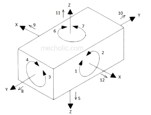
To make sure the proper fixing of the part we need to restrict all 12 degrees of freedom of the workpiece. The major portion of time of BIW fixture designer is spent to deciding how to fix these all DOF.
The jig and fixture are tools used for holding the work piece in a correct location for mass production. Various types of fixtures (like drilling fixtures, milling fixtures, and welding fixtures) are used in industry. The 3-2-1 method is the fundamental principle for all types of fixture design.
5)Elaborate types of BIW Stations?
BIW Station is the part of BIW assembly line. The BIW assembly line is divided into zones & these zones are again divided into stations.
The BIW stations are further divided into following
1) Tool stations
2) Gripper stations
3) Stand station
4) Miscellaneous stations
1)Tool stations -
A)Geo Fixtures -
- In BIW we consider Tack / Geo Fixture. In Geo fixture tack welding done for all the parts to be assembled in that fixture.The geo fixture defines the geometry of the part.
- All the parts must be located with two locating pin ( Pin can be common for two or more parts.)
- These Jigs have tight accuracy standard . In case of Geo fixture all the machine parts individually should be made with max tolerance of ± 0.02 mm . Where as positional accuracy of pin should be within -0.15 mm.
- In Geo fixture spots/ MIG welding done in such sequence that after taking out from the fixture it achieve the desired accuracy and doesn’t get disturb during transportation from Geo fixture to re-spot fixture. Geo fixture control the sub assy accuracy in all the 3 axis.
Fig- shows Body side geo fixture
B)Re-spot Fixtures -
- In BIW we consider Re-spot Fixtures. In Re-spot fixture remaining tacks are completed.
- Suppose in a assembly we need 50 weld tacks. On one station we cannot complete all these operation beacause it will take more time & another station relative to the assembly will be in ideal condition.
- In this type of case, we carefully choose some weld tack points which will define the geometry of the part & also the assembly will not get deformed after opening the clamping or in transportation due to the welding stresses.
- The remaining weld tacks will be completed in Re-spot fixture as per needed. By performing this kind of operation no station will be ideal Hence we use Re-spot fixtures.
- Re-spot fixtures also have very tight positional accuracy. Re-spot jig pin tolerance will be -0.28 mm.
C) Marriage Fixture-
- As name suggests the marriage of different assemblies is carried out in this fixture.
- In different zones of assembly line different assemblies are completed like under body, Side body, Front body, Rear body etc.
- After this all the parts comes at the station where this all parts are gets assembled by using various joining techniques like welding, Gluing, Riveting etc. This station is called as marriage tool.
D)Framer Fixture -
- Framer fixture is next station after the marriage fixture.
- In framer fixture the roof is attached to the output of the marriage fixture & it form like frame hence it is called as framer tool.
E) Checking Fixture -
- These are used to check the assembly of parts, Tolerance ,Dimensions & coordinates.
- It can be of gauge type, Fixed type ot automated checking fixture.
- A checking gauge is a tool where work piece is hold & different measuring gauges are introduced to ensure dimensions & repeatability.
- A fixed type checking fixture is used where the work piece is fixed with clamps & pins & CMM is used which measures the corodinates of the different points of panel or assembly. Then is compares with the CAD data & gives report.
2)Grippers -
A gripper is a device which enables the holding of an object to be manipulated. The easier way to describe a gripper is to think of the human hand. Just like a hand, a gripper enables holding, tightening, handling and releasing of an object. A gripper is just one component of an automated system. A gripper can be attached to a robot or it can be part of a fixed automation system.
Different grippers are used in BIW as follows,
A)Material handling gripper -
- As the name suggest These grippers are used for material handling.
- These grippers can pick assemly from one station & will drop the assembly to another station.
B)Process grippers -
- These grippers are used to carryout some specific process like gluing, welding, riveting etc. in addition with material handling.
- The gripper will goes under gluing stand in case of gluing process & will goes under the pedestal weld stand in case of welding process.
C)Combo Gripper -
- Combo grippers are the one which can carry out multiple tasks like it can do material handling & also it can carryout some specific process like gluing, welding etc. as well.
- Weld gun + Gripper
D)Dual Gripper -
- These are two sided grippers. In case when we want one LH & one RH part, these grippers are used. It can handle the material from one station to another station
- Gripper + Gripper
3)Stands -
Stands are used to hold part when not in use or also it is used to mount some parts or bodies on it.
Different stands are used in BIW
A) Pedestal stands -
- Weld gun is mounted on the fixed stand which is mounted to the floor permanentaly. The gripper can carry the panel under the stand to do the operation.
B) Gluing & sealer stand -
- Gluing gun or sealer gun is fixed to a welded or a standard stand which is grouted to the floor permenantaly.
C) Docking stand -
- The robots have some limitations such as the payload capcity of the robot & also due to lack of space.
- When we select the robot for multitasking it can't do both the task simultaneously due to limitations.
- In this kind of case, we add docking stand to put some equipment which is not in use for the current operation but will be required for next operation.
- Hence the robot can drop a gripper or gun & pick next oparation equipment to complete the task from the docking stand.
D) Date stamp stand -
- Every manufactured product have some data to stamped or to be embossed on it like serial no, batch no, Date etc. for some future reference or for data collection.
- The required data is stamped or embossed by using the stamping device mounted on the stand.
4)Miscellaneous stand -
A)Curing- After gluing it needs some time to cool down , so we put assemly on some belts & it will take the panel to another station & meanwhile gluing will cool down.
B)Buffer stand- After some operation we can put the no. of assemblies in this stand which is buffer stock & it can be transported to another station in easy way. They are also used to store the inventory while the machine is under going for some maintainence.
C)Take out trolleys - It used to take out some panels for inspection to rectify the process is going in right or not between the cycle.
D) Conveyor - Conveyor is the rotating path which tranport the parts to the next station which are kept over it.
6) What are the basic terminologies used in the BIW fixture?
- The following terminologies are used in BIW
A) NC/Mylars/Fingers- Mylars is the component which holds the panel while operation. These are placed from top side & from bottom side also. The top side Mylars called as Clamping Mylars & the bottom side Mylars called as Resting Mylars. Every clamping Mylars have resting Mylars. It dont allow deformation of the part due to welding stresses.
B) Principle locating point (PLP) - These are the points which are used for the accurate location of the part to maintain the geometry of the assembly. There are lots of holes on the panel which are not accurate due to stamping operation. The PLP are defined in the drawing. The positional dimensions or relative dimensions are very precise in stamping & in fixtures also.
C) Risers - Risers are of different type like L-typer rises, Square tube riser etc. Riser is the manufacturing part which gives height to the assemblies.
D) Blade- Blades are plates mounted on the riser. Other parts like cylinder, arms etc are mounted on the blade.
E) Shims - Shims are the small part which comes with the thickness of 0.1mm, 0.2mm, 0.5mm etc. These will compensate the stackup tolerance which reflects at the panel holding part called Mylars. We give tolerance to all the parts of the fixture. Due to this tolerance the Mylars will either lift up or goes down from its defined position. If the Mylars goes down from the defined height it will make impression or dent on the panel. If the Mylars lift up then there will be a distorsion due to welding stress. To adjust the Mylars At its defined position we use shims so the panel won't deformed & also dont get any impression on it.
F) Rough locators - The operator can place the part in wrong orientation mistakanely. The rough locator will work as a guide while placing the part in the fixture & the part will be loaded in desired orientation. It is a part of fool proofing.
G) Hardwares - Hardwares are like the Hex head bolts, Allen Bolts, Hex nuts, Spring washers, Self locking nuts etc.
H) CMM - CMM stands for coordinate measuring machine. It is a device that measures the geometry of physical objects by sensing discrete points on the surface of the object with a probe. It generates report my comparing the data with the CAD file data.
I) Unit - The fixture is the assembly of different types of units to form a fixture. There are different units like pin unit, base unit, clamping unit etc.
J) Number plates - Number plate is the aluminium embossed plate placed on the each unit for easily recognising the unit.
K) Name plate - The data like manufacturing company name, fixture type, Fixture weight etc. is embossed on the plate & joined to the fixture.
L) Clamp Arm - Clamp arm is the part of clamp unit which moves over a axis. Over clamp arm the Mylars are mounted.
M) Pivot - It is a axis about which the clamp arm will rotates.
N) Class A Surface/Skin surface - The outer panels of the car like hood, door, backdoor, fender,roof etc. are visible to the customer. The outer panels should be asthetically very good. No any scratches or dent is acceptable over it. While designing the fixture to the skin surface the clamping material should be soft, so that it could not able to left any impression or dent over skin. generally nylon or pu material is used for clamping purpose.
O) Reed switches & sensors - These are the electric componnents used in automated fixtures. The reed switch is an electrical switch operated by an applied magnetic field. The detects the panel is loaded or not is done by sensors.