Week 1:- Introduction to BiW and Fixtures Challenge













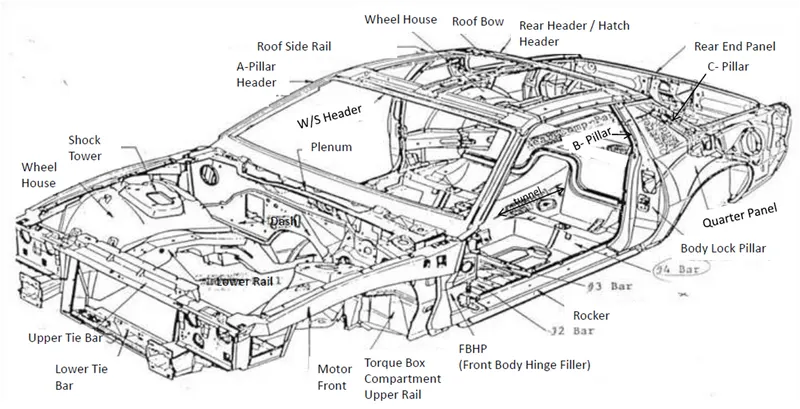
- A,B,C,D Pillars :-
- Dashboard mounting panel
- Windscreen & Rear Window rail
- Cant rail
- Roof structure
- Side Sill
- Quarter panel or window
- cross member
- Heel Board
- Front & rear Valance
- Scuttle
- Firewall
- Floor, seat & Boot pan
- Front & rear Spring tower
- Central Console
- Front & Rear Wheel arch
- Toe board
- Heel board











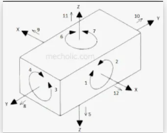


(3) minimum: Three locators blocks to established part plane. Three locators, or supports, are placed under the work piece. The three locators are usually positioned on the primary locating surface. This restricts are one axial movement downward, are 4 radial movements. Together, the three locators restricts five degrees of freedom.
(2) Round locating pin in a round hole that defines locating in four directions (4-way) perpendicular to the plane previously established. This restricts four axial movement.
Round locating pin in a slot that defines two of the directions of the other pin (2-way). This resticts two axial movements.
(1) Clamping unit are usually positioned on the primary clamping surface. This restricts are one axial movement upward.
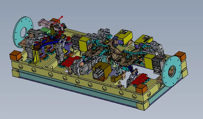









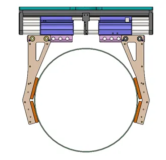
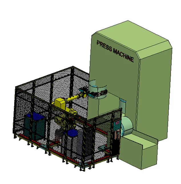
- Stand stations:
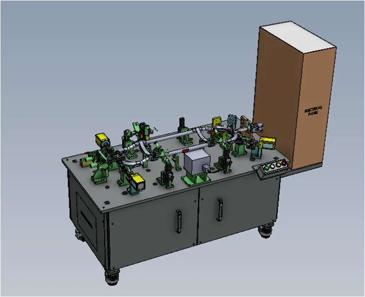
Stand stations are used to hold or mount the workpiece
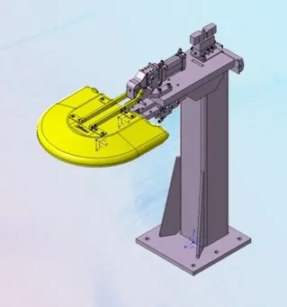
Image 5.2 : Typical stand station
- Pedestal stand: These are fixed stands fixed on the ground permanently to which tools are attached. Such that gripper can move along the stand to make the processing done
2. Gluing and sealer stand: In this stand the gluing gun or sealing gun is attached and this stand is fixed permanently to the ground
3. Docking stand: Robots have some limitations in their pay load capacity or it may have to do multitasking, in such situations these docking stands helps for giving temporary space or rest to the workpiece. Hence the robot can do multitasking or it can overcome payload limitations
4. Date stamp stand: These stand helps to emboss the date of manufacturing or batch numbers or reference numbers on the parts
4. Miscellaneous stations:
- Curing: These sands helps in providing curing time for the assembly operations such as gluing or helps in cooling down the components after operations
2. Buffer stand: These helps in storing the components in this stand so that no over flow or lack of flow is not obtained in the assembly line. These creates buffers in the assembly lines
3.Take out trolleys: These trolleys are used to pull out the components from the assembly lines for inspection
4. Conveyors: These are rotating belts or chains which helps in transport the workpiece from one station to other stations.
6. What are the basic terminologies used in the BIW fixture?
- Principle Locating Point: These points help to accurately locate the part to maintain geometry of the assembly
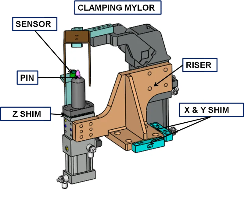
- Risers: These provide support and height to the assembly base.
- Blade: These are plates mounted on the riser
- Shims: These are very small parts with lesser thickness which helps to balance the dimensional tolerances
- Rough locators: These is a kind of fool proofing which allows the operator to load the component only in the correct location and orientation
- Hardwares : These are bolts, nuts and self locking nuts etc.
- CMM: Coordinate measuring machine is machine that measures the geometry of the component using a probe by physically sensing at discrete points
- Unit: The fixture assembly consists of different units such as base unit, gripping unit etc.
- Number plate: It is a plate which have numbers embossed on it. Which helps in recognizing the part later
- Name plate: It is a plate which consists of all the details of the fixture embossed on it.
- Clamp arm: It is an arm of the clamp which rotates along the pivoted axis
- Pivot: It is the axis or bearing about which the clamp arm rotates
- Class A surface/skin surface: These are the outer aesthetic components which are visible as the final assembly. While designing fixtures to such a parts the fixtures should be of soft materials and should hold firmly
- Reed switches: These are the electronic switches which are operated by the sensors or sometimes manually
- Sensors: These are the electronic devices which senses the components on the fixture and helps to operate or send input commands to the other mechanical or electronic components
- Operation sequence :- These sequences is used for overall working of fixture in which have cylinder details with particular & sensor will sense the presence of panel child part.