Week 1:- Introduction to BiW and Fixtures Challenge
1.What is BIW & define its parts ?
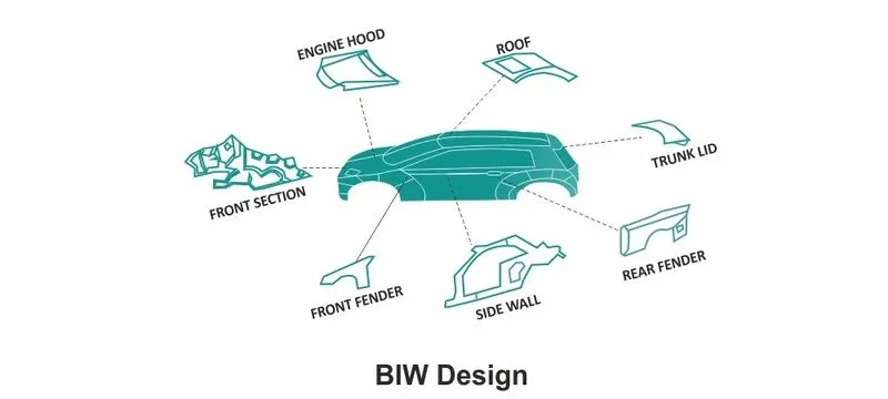
BIW (short for Body in White) is a stage in automotive design and manufacturing. BIW refers to the body shell design of an automotive product such as cars. It is just a sheet metal welded structure. BIW will not have doors, engines, chassis or any other moving parts.
Body in White (BIW) refers to the welded sheet metal components which form the vehicle’s structure to which the other components will be attached, i.e., engine, chassis, exterior, and interior trim.
Automobiles have always been the greatest invention as it connects each and every part of the world. To manufacture them is a very long and complex process. “Body in White (BIW) “, sounds new? Well that’s great if it doesn’t. But if you heard this word right now, I will take you through the interesting facts in this journey. BIW refers to the stage in automobile manufacturing in which the vehicle body sheet has been assembled. This means that the vehicle’s body frame has been joined together including doors, hoods, trunk, bumper and deck lights. At this stage all the chassis assemblies are welded together before painting.
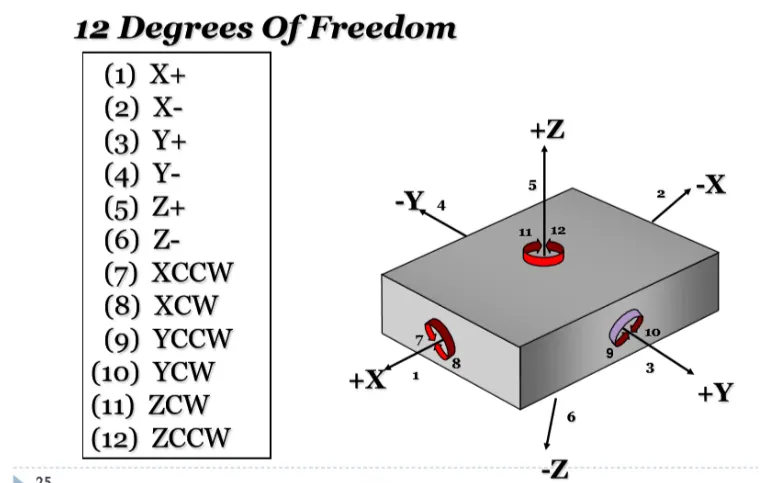
- Translational movement along X -axis
- Translational movement along Y-axis
- Translational movement along Z-Axis
- Rotational movement along X -axis
- Rotational movement along Y-axis
- Rotational movement along Z-Axis
BIW FIXTURE TYPES
PRODUCTION FIXTURE-
As name suggest this fixture is used for mass production. It is fixture on which car body get assemble & go to end customer. These types of fixture require high constancy through its operation to maintain geometry of parts. So material used for these types of fixture should be well tested as well as hardness level aesthetic. The quality in terms of dimension, tolerance should be met. These fixture need to maintain after certain period of time. The assembly &disassembly should be easy as low as possible. So maintenance person can easily access with saving time.
PRE-PRODUCTION FIXTURE
It is generally defined as prototype fixture. It is designed to study feasibility of initial batch production to check which things are need to be improving before starting production. This fixture is base of production fixture in benchmark and criteria & helps us to rectify error. In preproduction operation fixture there will be more involvement of manual operations, engineer, and quality person. It has larger cycle time than production fixture. But won’t practice by designing pre-production fixture because it takes lots of time & cost. We have to maintain cost of car as low as possible so we directly go to production fixture by considering standards, checklist to maintain error free production.
CHECKING FIXTURE
As name suggest this fixture is used for checking assembly which came out from geo fixture. Checking fixture are same as geo fixture except there are no operation done like welding, gluing or hemming. Instead of that we use different in built gauges or external gauges to check various dimension, gap, relative dimension, tolerance. These data is compared with data provided by designer or design team of that particular. The geometry of welded part also checked in this fixture to ensure part maintains the required dimension & geometry.
4. What is the basic principle of fixture design?
PRINCIPLE OF FIXTURE DESIGN:
In the automotive tooling industry you will hardly get any designer who does not know 3-2-1 principle.If the any part e.g steel block to be machined using milling machine;1st question the milling machine operator will think how I will hold the part.Operator will use the various clamp to hold the job to withstand the cutting forces.Any part which has to be fixed during welding or during machining process has to be fixed. with this principle. Every object is having 6 degrees of freedom.
1) Translational movement along X -axis
2) Translational movement along Y-axis
3) Translational movement along Z-Axis
4) Rotational movement along X -axis
5) Rotational movement along Y-axis
6) Rotational movement along Z-Axis
5. Elaborate types of BIW Stations?
The B/W stations are further divided into following
1) Tool stations
2) Gripper stations
3) Stand station
4) Miscellaneous stations
1)Tool stations-
Geo station:
In this station geometry of two parts are fixed. it can be either using welding or riveting . In this station precision and geomatry of the finished product is defined Locating pins have closer tolerence of 0/-0.15.
Suppose the hole dia of panel is 16mm then the pin dia minimum can be 15.85.
Diameter of locating pins should be lesser than the panel hole dia. So Tolrence in locating pin is given in negative value.
2. Respot Station :
Once product comes out of the Geo Station and there are left out spots where spot welding or riveting is to be done. then it is moved to another station , that station is called Re-spot station.
These left out spots may be the due to clamp plan, cycle time,robot reach ability or any other various reasons.
In this station pins ahve tolrence upto 0/-0.28.
3. Pedestal Station :
In this station , Pedestal gun is mounted on a tool and panel is manipulated manually or by robot to weld the panels.
Pedestal station is generally a Re spot station.
Re spot station and Pedestal station, both perform same kind of operation . but to decide whether to go for pedestal or a re-spot station some parameters needs to consider like cycle time, floor space, no. of welds, clamp plan, or size of the panel.
4. Loading Station :
This station is used for loading of panel and same station is used to change the orientation of the if it is required in the upcomin station.
Sometime this station is used when Robots are unable to transfer panel from one station to another.
5. Buffer Station :
This station is used to make the balance between the process.
Some stations carry out procees in lesser time as compared to their respective stations.In that case panels can be stored in one sation so that assembly line process remains smooth.
6. Sealer Station :
In this station Sealant application is carried out.This process can be carried out manually or by using robots. Sealer is used in between two panels so that panels do not flatter due to friction.
7. Marriage Station :
In this Station inner and outer panels are joined. In this station to avoid the imprssion on the outer panel(A class surface), copper strips are used in betweenn the weld tip and A-class surface.
8. Curing Station :
In this Station product recieved after sealing application, is kept idle at ambient temperature, which allows sealent to get dry with better bonding between the panel.
H) CMM - CMM stands for coordinate measuring machine. It is a device that measures the geometry of physical objects by sensing discrete points on the surface of the object with a probe.
1) Number plates - Number plate is the aluminium embossed plate placed on the each unit for easily recognising the unit.
K) Name plate - The data like manufacturing company name, fixture type, Fixture weight etc. is embossed on the plate & joined to the fixture.
L) Clamp Arm - Clamp arm is the part of clamp unit which moves over a axis. Over clamp arm the Mylars are mounted.
O) Reed switches & sensors - These are the electric components used in automated fixtures. The reed switch is an electrical switch operated by an applied magnetic field. The detects the panel is loaded or not is done by sensors.