Week 1: Channel flow simulation using CONVERGE CFD
Objective
To study simulation of channel flow with different mesh size
Creat Geomentry
x=0.01,y=0.01,z=0.01m
set up
material
species
N2,O2
Simulation Parameter
Steady state
Simulation time parameter
End time-15000 cycles
Boundary
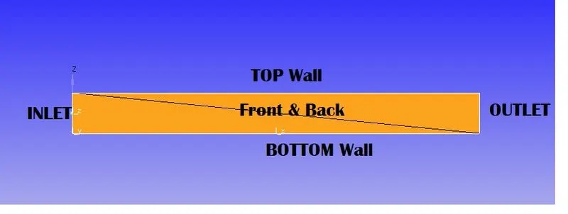
| Boundary Condition | |||
| Region | |||
| inlet | P=100001 | O2=0.23 | N2=0.77 |
| outlet | P=100000 | ||
| top & bottom | wall | Noslip | |
| Front | Two_D | ||
| back | Two_D | ||
Base Grid
| mesh size | |||
| cases | dx | dy | dz |
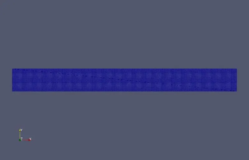
| case1 | 2e-4m | 2e-4m | 2e-4m |
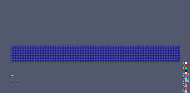
| case2 | 1.5e-4m | 1.5e-4m | 1.5e-4m |
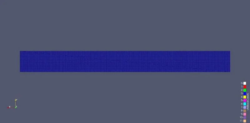
| case3 | 1.0e-4m | 1.0e-4m | 1.0e-4m |
Export set up data
run simulation in cygwin to get result for different cases
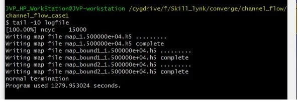
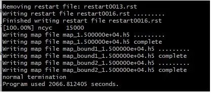
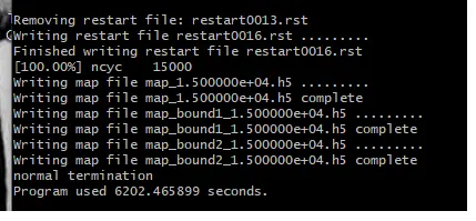
Out put result
case1
Case2
Case 3
Postprocessing
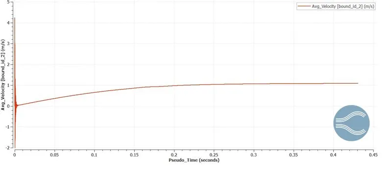
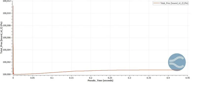
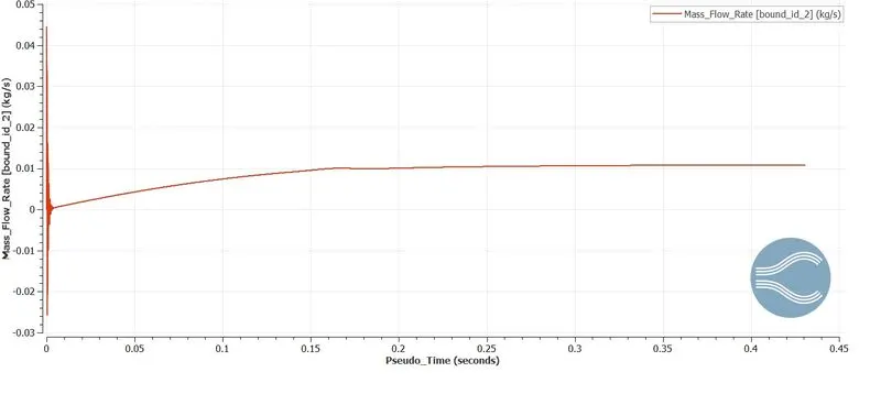
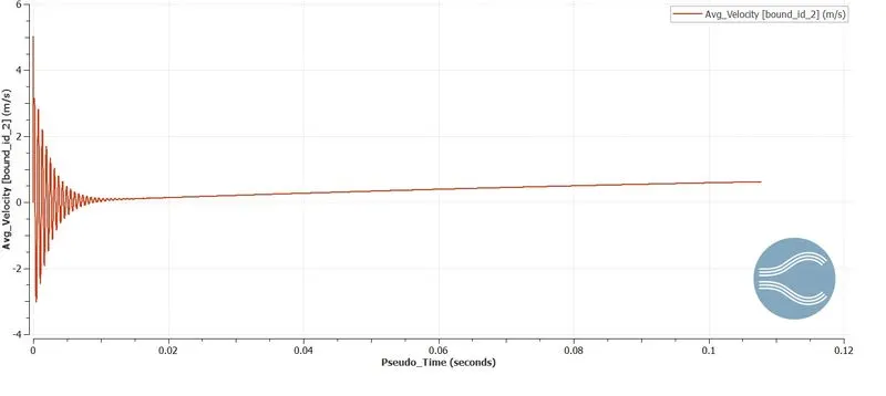
Graph Converge
case1
Velocity
Pressure
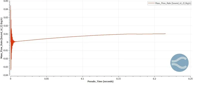
Mass flow rate
case2
Velocity
Pressure
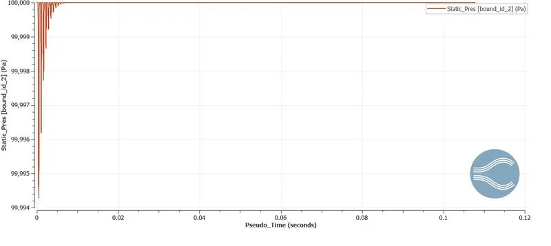
Mass flow rate
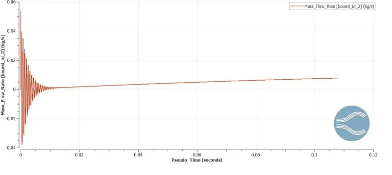
case3
Velocity
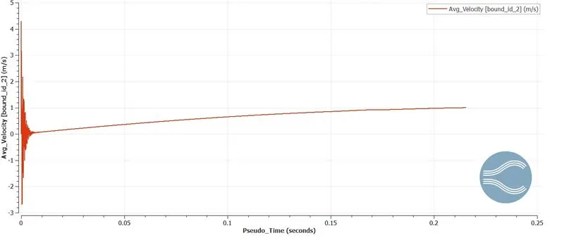
Pressure
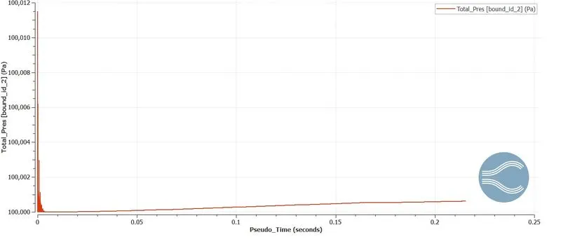
Mass flow rate
Paraview
Mesh
case1
case2
case3
Contour
case1
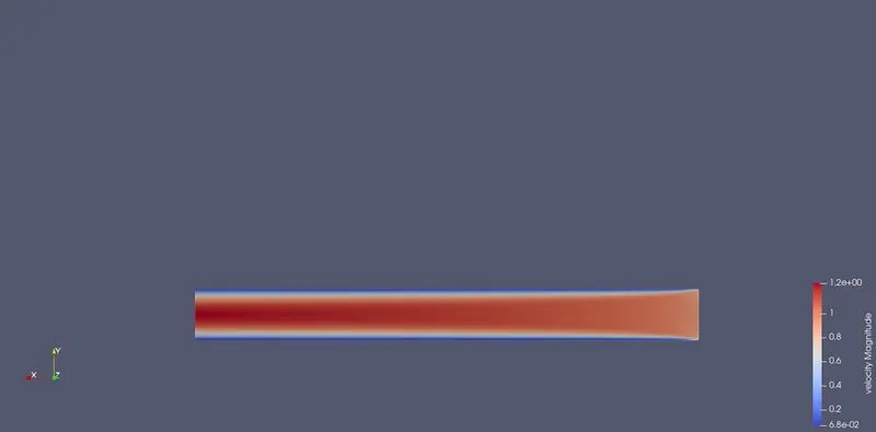
Velocity
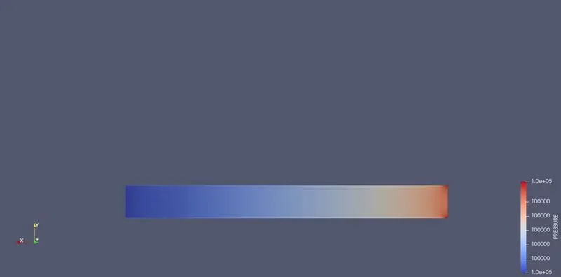
Pressure
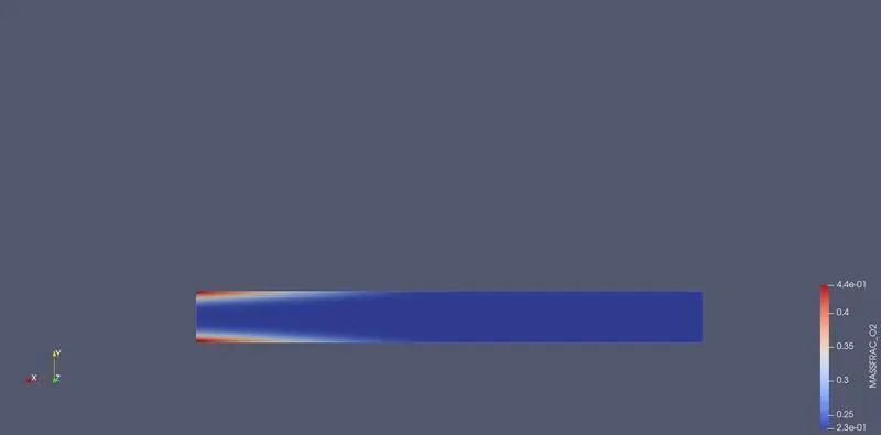
O2
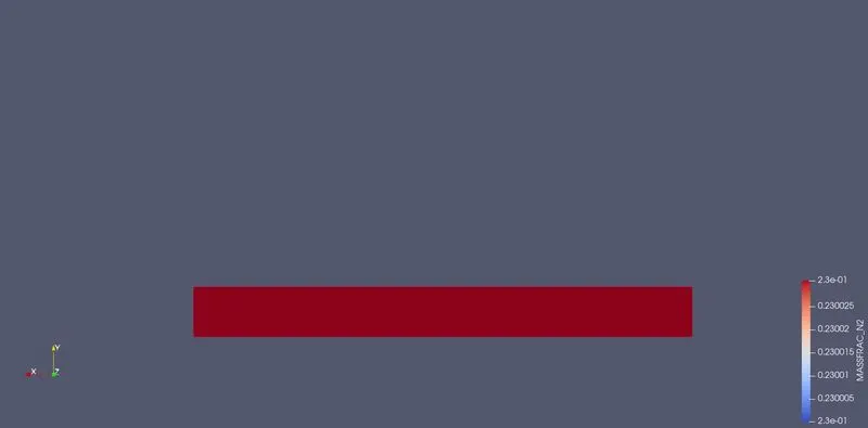
N2
case2
Velocity
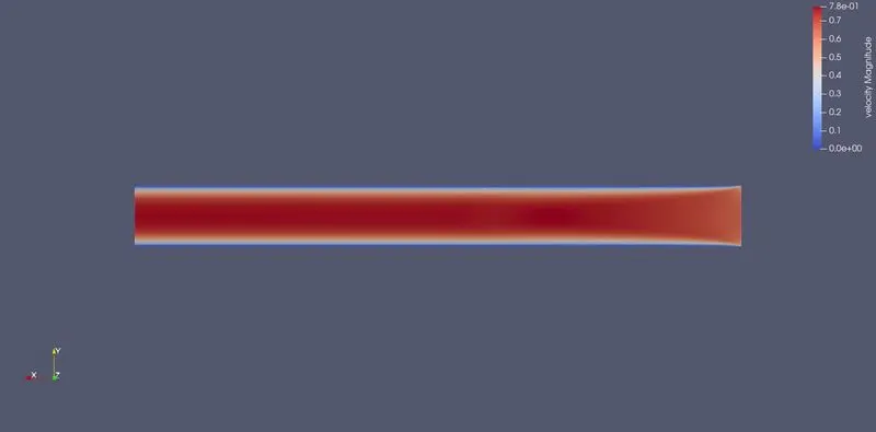
Pressure
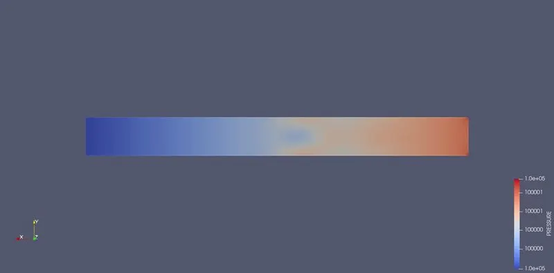
O2
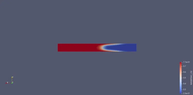
N2
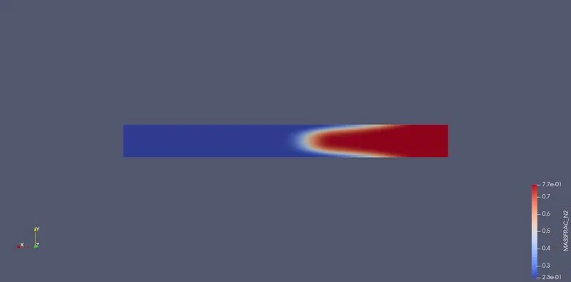
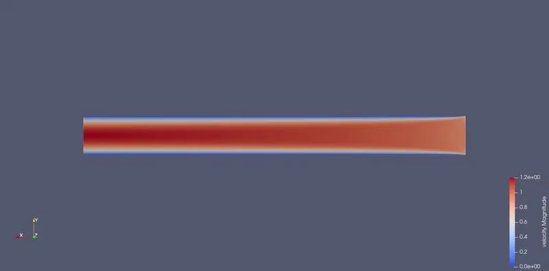
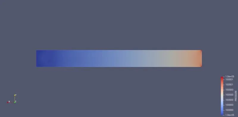
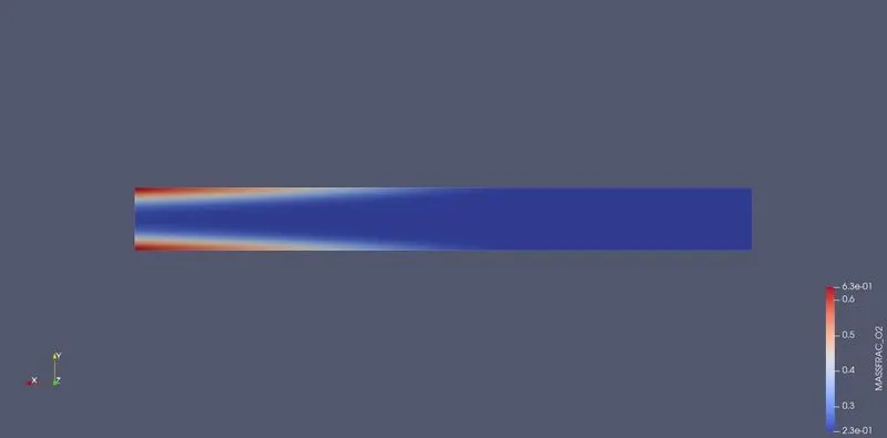
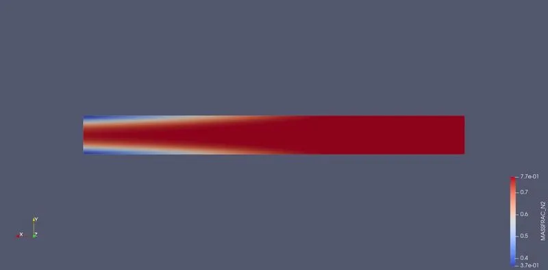
case3
Velocity
Pressure
O2
N2
Animation
Case1
Velocity
Pressure
N2
O2
Case 2
Pressure
Velocity
O2
N2
Case3
Velocity
Pressure
O2
N2
Conclution
simulation is done with 3 different cases in converge and cygwin
simulation power Take more for case due to number of grids and smooth graph