Week 1: Channel flow simulation using CONVERGE CFD
Aim: Channel flow simulation using CONVERGE CFD.
Theory:
Channel flow is an internal flow in which the confining walls change the hydrodynamic structure of the flow from an arbitrary state at the channel inlet to a certain state at the outlet.
The simplest illustration of internal flow is a laminar flow in a circular tube.
Simulation Procedure:
Converge setup:
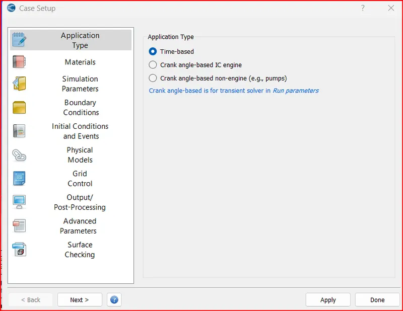
Application Type:
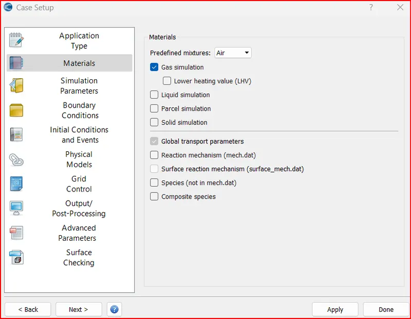
Materials:
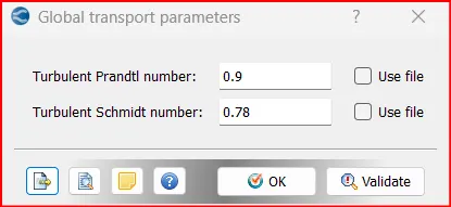
Global Transport parameters:
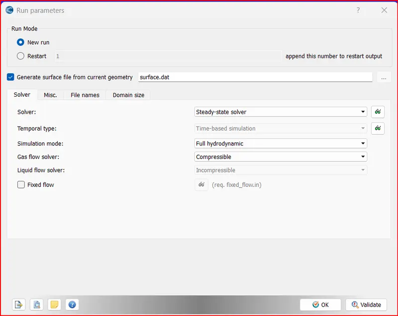
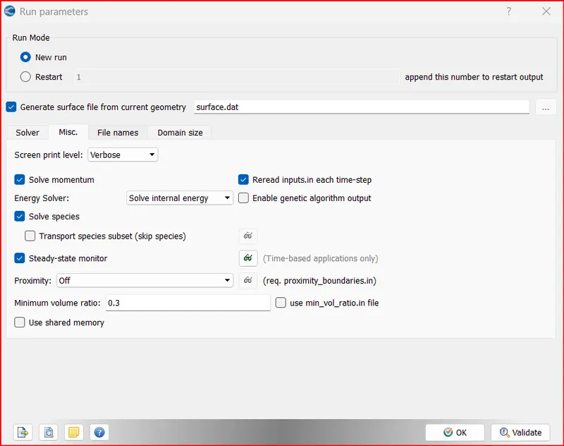
Run Parameters:
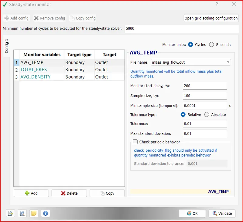
Steady state Monitors:
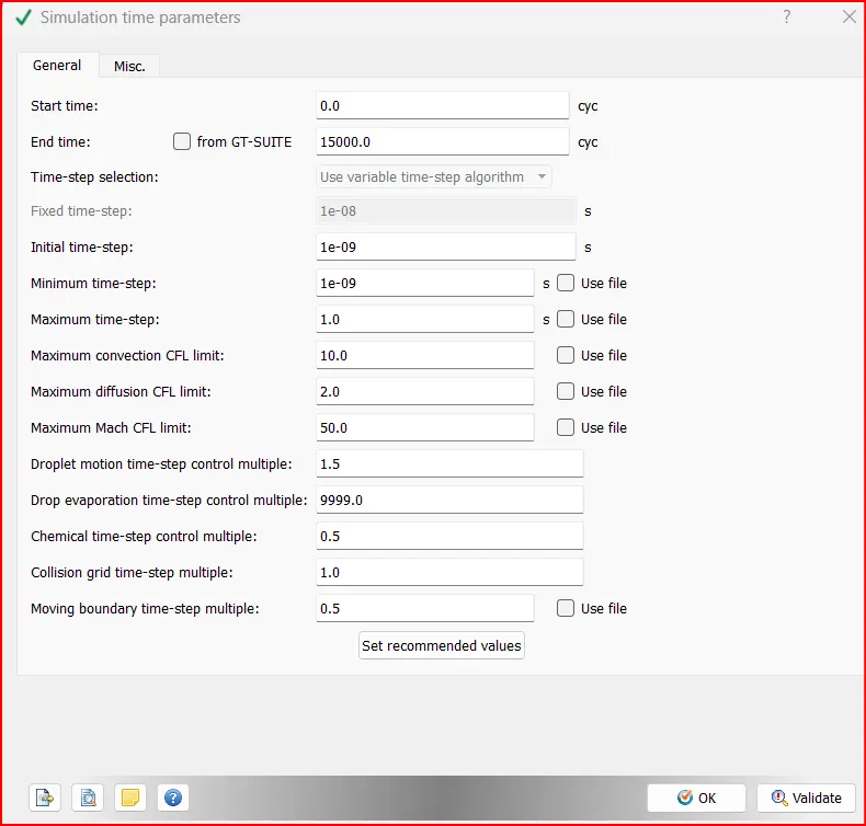
Simulation Time parameters:
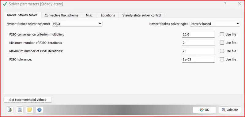
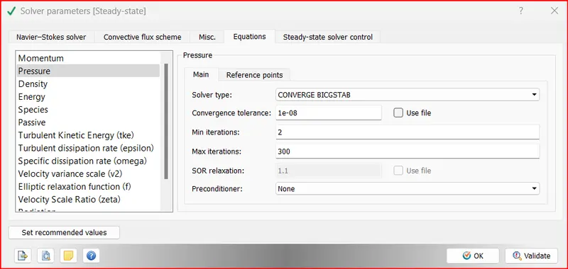
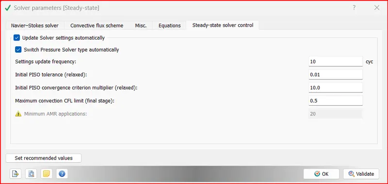
Solver parameters
CASE 1:
dx = 2e-4m, dy = 2e-4m, dz = 2e-4m
Surface with Edges:

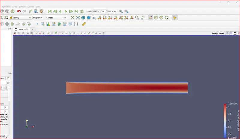
Velocity Contour:
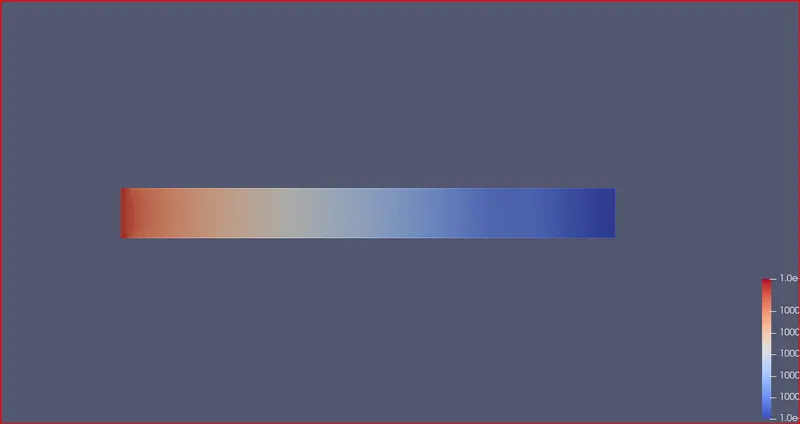
Pressure contours:
Line plot:
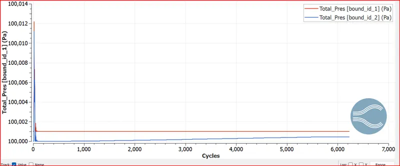
Pressure Plot
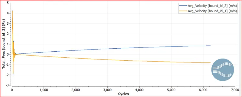
Velocity
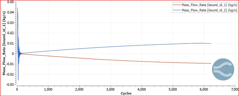
Mass Flow Rate
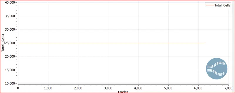
Total Cells
Video Link: https://youtu.be/uA-oW0ESaUM
CASE 2:
dx = 1.5e-4m, dy = 1.5e-4m, dz = 1.5e-4m
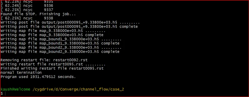
Total 9338 cycles:
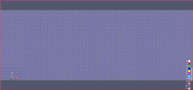
Surface with edges
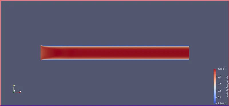
Velocity Contours
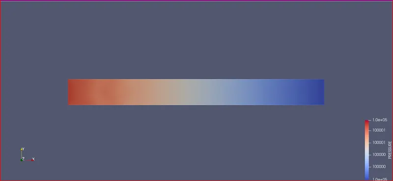
Pressure contour
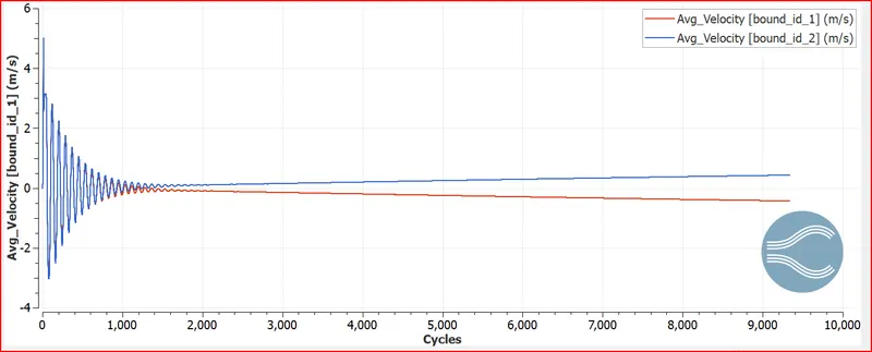
Velocity plot
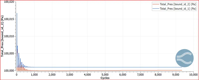
Pressure Plot
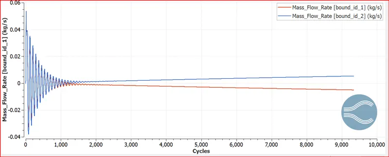
Mass flow rate
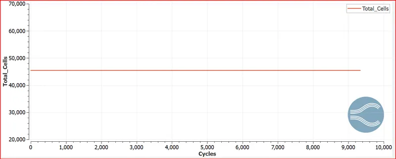
Total Cell count
Video Link: https://youtu.be/1n9lYfws63A
CASE 3:
dx = 1.0e-4m, dy = 1.0e-4m, dz = 1.0e-4m (If this is too much for your PC, use 1.2e-4m)
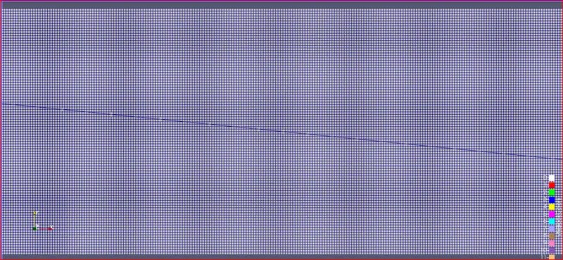
Surface with edges
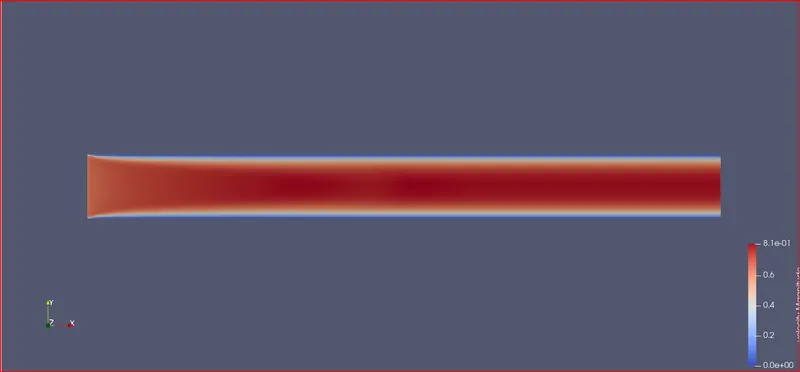
Velocity Contour
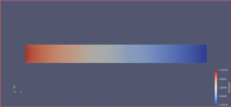
Pressure Contour
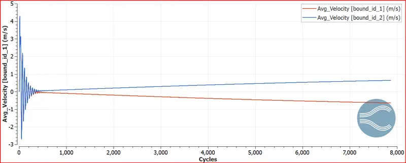
Velocity plot
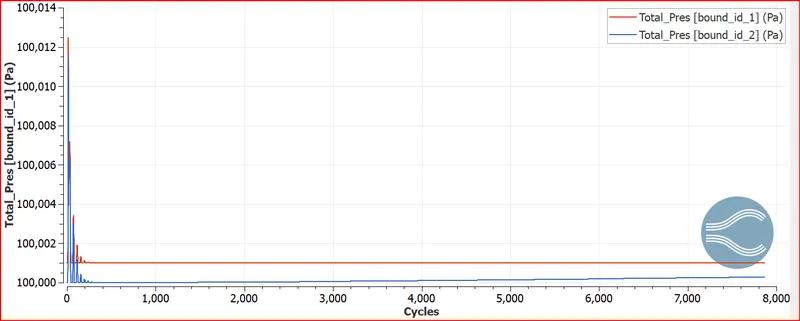
Pressure Plot
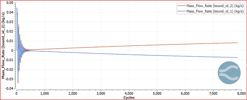
Mass flow rate
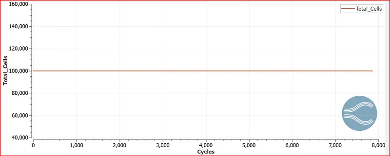
Cell Count
Video Link: https://youtu.be/y0jp29B-fNQ
Conclusion:
Channel flow case set up is done in the converge software and simulation is done for three diferent mesh sizes.
It is observed that as the mesh size is decreased the cell count increases and also the computational time increases.
The flow is developed using the pressure difference between the inlet and outlet.
Due to no slip condition at the wall th velocity becomes zero near the wall as seen in the contour.