Week 1 Challenge
Q1.
1) Steps involved to upload a .std file through web mails are as follows;
- Open the STAAD pro software and locate the share option available on the introduction screen.
- After clicking on the share button, select send mail option.
- Then, browse for the. Std file on your machine & send it.
2) Different materials that can be designed using STAAD Pro. are as below;
- Concrete.
- Steel.
- Aluminium.
- Timber.
- Composite sections
3)
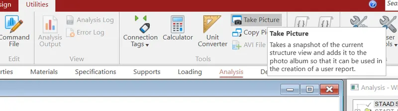
- YES, it is possible to capture images in STAAD Pro.
- We can take pictures of models and structural results in staad pro using the take picture command, the command is available in the utility panel with a camera logo
4) Three ways by which you can create a model in as STAAD pro are as below;
- Analytical model.
- Physical model.
- Building planner model.
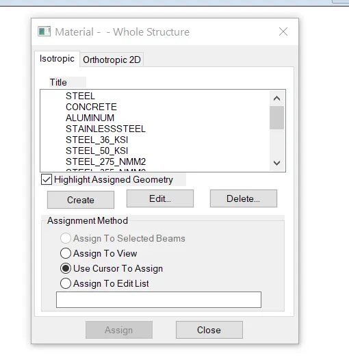
5)
- Go to the properties panel.
- Click on materials.
- Select a desired material from the list
- Concrete / steel / aluminum / stainless steel etc.
- Then check the assignment method based on your preference like use cursor / assign to view etc.,
- After checking the radio button, go ahead and assign the material property to your model.
Q2.
The six Design parameter involved in RCC design are as below;
- Clear cover
- FC compressie strength of concrete
- FY Tensile Strength of steel
- Max main Dia of bar
- Code of practice
- End conrete design
2)
The different cursor types that are available in STAAD Pro are listed below:
- Nodes cursor.
- Plates cursor.
- Beams cursor.
- Plates and Solid cursor.
- Loads cursor.
- Solids cursor.
- Physical Member cursor.
- Geometry cursor.
3)
First go to view option in the ribbon there we can get option like as below;
- Top view
- Isometric view
- Front view
- Left view
- Right View
- Botttom view
- Back view
4)
Go to the support command in the tool palet command
- Click on create support command
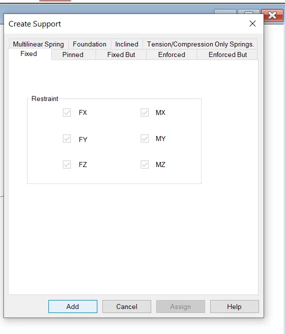
- There we can get option like fixed support , pin support , Fixed but
- Enforced but support
- Cable support
- Inclined support
5)
First of all lets understand what is DBR? So the DBR is the Design Brief Report.So basically DBR is a short brief of what you are going to make,why you are going to make,where you are going to make. In short it is a core detail of our project. So the five topics that will include creating DBR is listed below:
- Name of the project and the location of the project.
- Structural Layout.
- Introduction to the construction methodology.
- Quality Assurance and Quality Control.
- Budget of the Project
6)
- It is used for 3D model generation, analysis and multi -material design .
- The STAAD .Pro supports several steel , concrete and timber material in a seprate member
- This seprate member will cordinate and the formed in to a structure.
Practical
1. Create a STAAD Model with the following Specification
a. A beam of span 16m
b. Support : Fixed on one end and Roller support(Horizontal) on the other end
c. A point load of 50 kN at the mid-point
d. Draw SFD and BMD using software
PROCEDURE:-
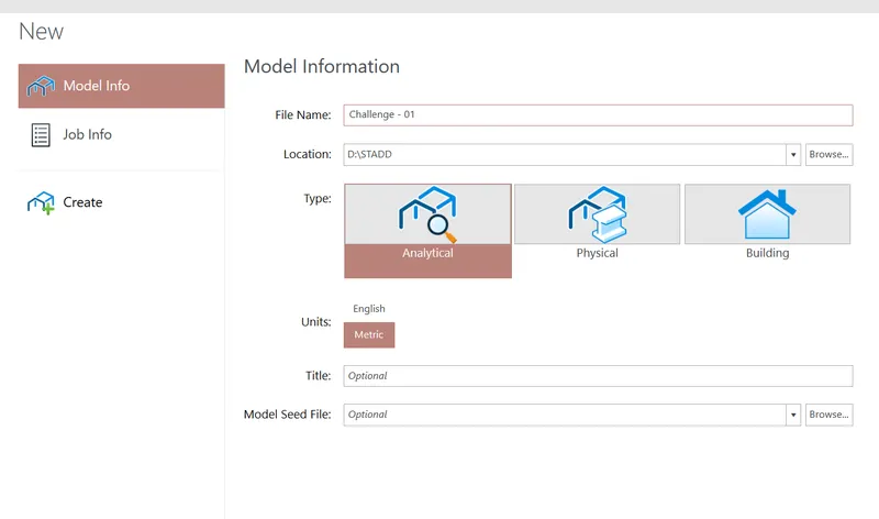
- Open the STAAD pro Software and Create a New Model
- The first step is to initiate the project in staad.pro
- The same can be done by clicking on the new option available on the staad intro screen.
- After clicking on the new model, you can feed the project details.
- Also, you will be asked to specify a location within your system.
- Then, click on create to start a new project.
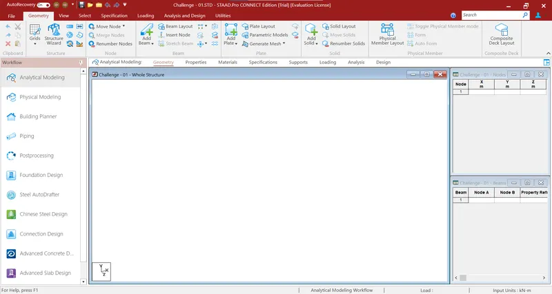
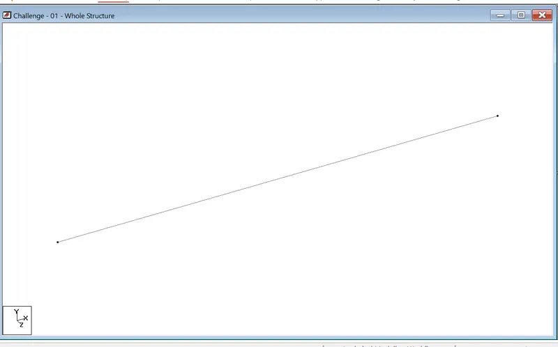
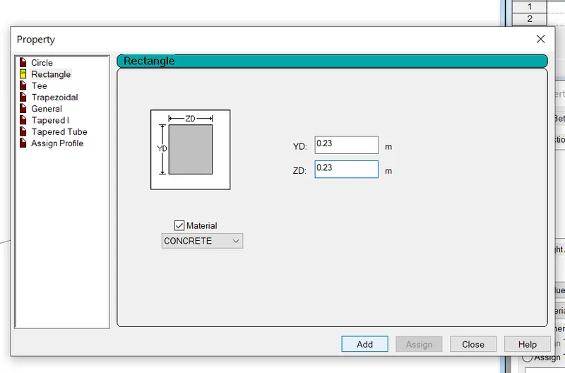
- Now draw the Beam of Required Span
- To model the proposed beam, go to geometry and create the first node at X-0, Y-0, and Z-0.
- Then, select the created node by switching to the node cursor.
- Press ctrl+c and ctrl+v.
- Specify the span length that is 16 meters in the X-direction and hit enter.
- Both the ends of the required beams are created now go to add beam>select first node and then second to create a beam of the proposed length.
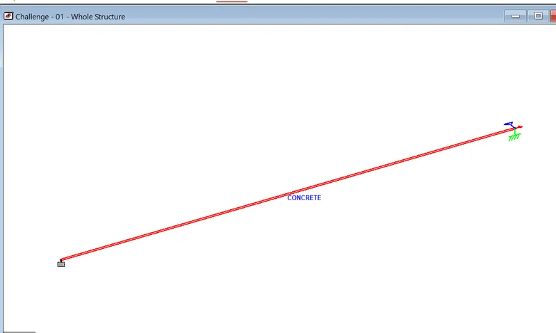
- Assign Support Conditions:
- Go to support>add>fixed>select one node>assign to selected nodes>enter.
- Similarly, create another node>fixed butt>release moments and horizontal restraints>ok>select the other node>assign to selected>ok.
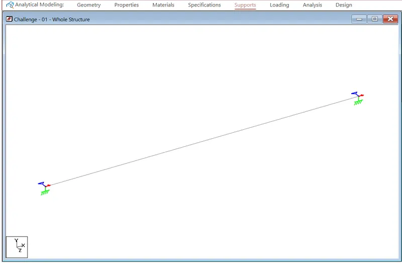
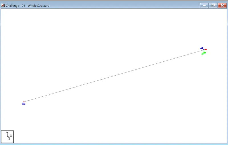
- Assign the Proposed Load
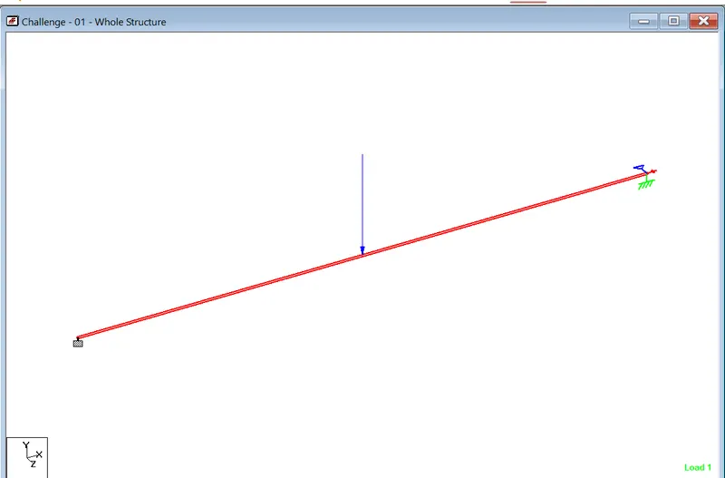
- Go to loads>create>member load>globa Y>-50KN>d1-8, d2-0>OK.
- Now, select the load and beam and check the radio button for assign to selected>apply>ok.
- Run the Analysis
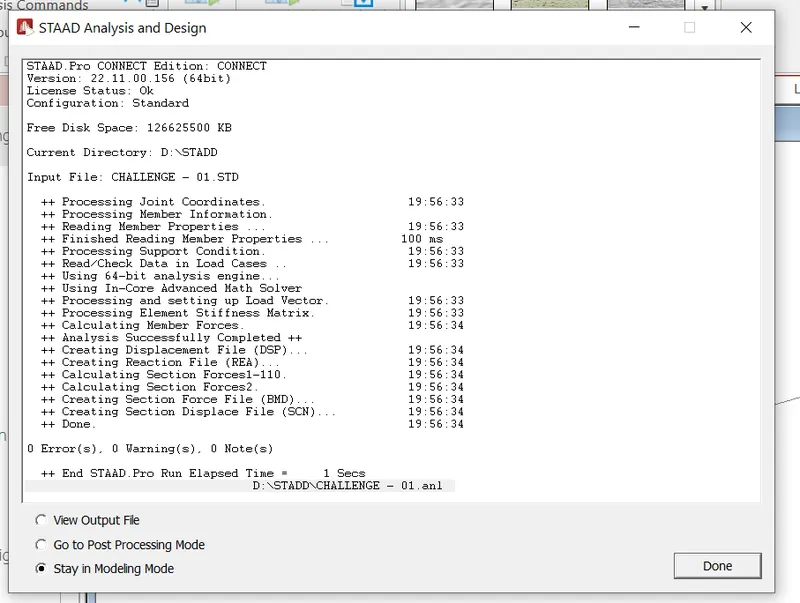
- After this, select the analysis method that is perform analysis from the design and analysis panel.
- Once you are done with setting up the analysis method, go ahead and run the analysis from the analysis and design panel.
- Wait some time for the analysis to get complete and look for errors and warnings.
- If there are no errors or warning signs upon completion of the analysis, you're good to go.
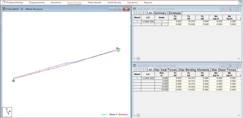
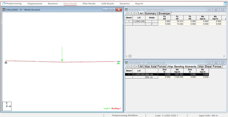
- Draw SFD and BMD
- Now, go to the post-processing mode>select the load cases>click apply>ok.
- Then, all the analysis results will be automatically visible on your staad screen.
- Select beam results>Mz for bending moment>Fy for shear force diagram.
- Make sure to check the annotate option to view the values along with the diagrams as inserted below:
Shear Force Diagram
BMD
RESULT:
To Apply supports,Loads and Analysis SFD and BMD diagrams are completed by using the staad pro software.