Week 1 Challenge
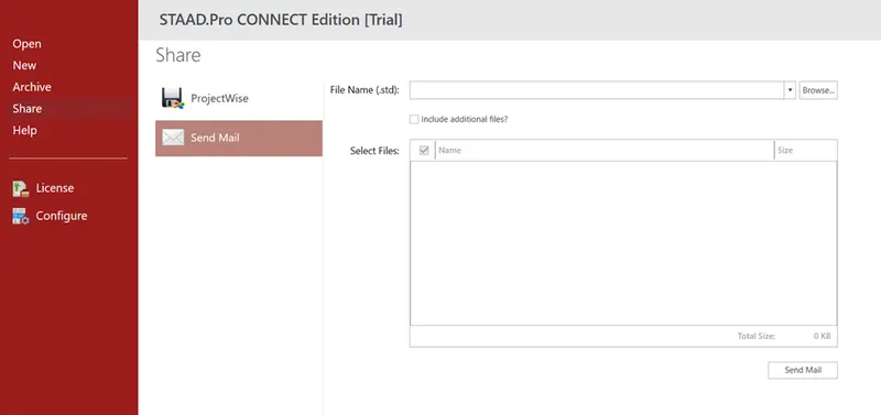
- Write the steps involved to upload a .std file through web mail?
Answer:
- Open STAAD Pro software
- Select share -> send mail -> browse and choose a .std file
- Click send mail
- Name the different materials that can be designed using STAAD Pro.
Answer:
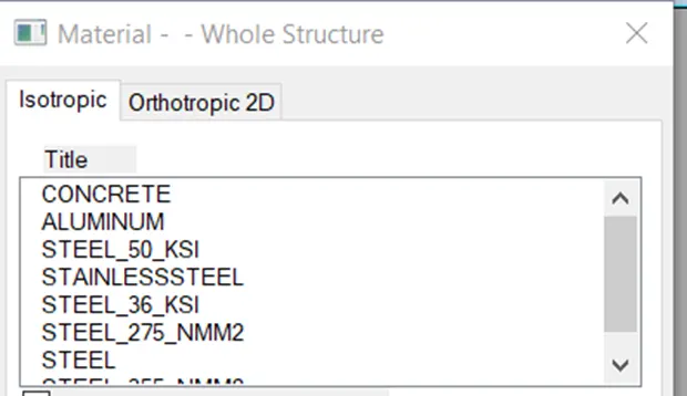
- Concrete
- Steel
- Aluminum
- Timber
- Composite material
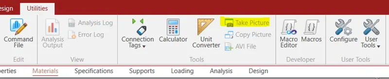
- Is it possible to capture images in STAAD Pro? If yes how?
Answer:
- Yes, The picture of the results or model can be taken form utilities tab
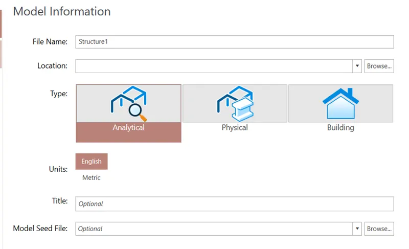
- Name the three ways by which you can create a model.
Answer:
- The 3 ways of modeling in STAAD Pro are,
- Analytical
- Physical
- Building modeling
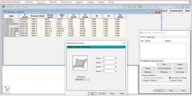
5.Write the steps followed to assign properties in a model.
Answer:
- Go to property tab
- Select the desired property like material, thickness, angle as shown below.
- Then, select the assignment method like use cursor to assign
- 1. Name any six-design parameter involved in RCC design.
Answer:
- Modulus of elasticity -E
- Density
- Yield strength of steel- fy
- Compressive strength of concrete- fck
- Effective length factor
- Width of the member
- What are the different cursor types available in STAAD Pro?
Answer:
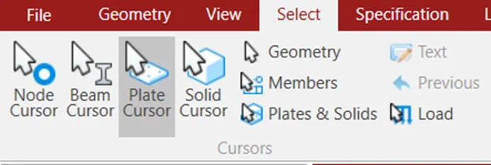
- The above cursors options are available under select tab -> cursor panel in STAAD.Pro
- How will you generate different views for a model? State the steps involved.
Answer:
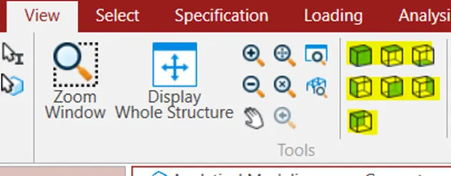
- Go to View tab and select the desired view to create a view type like
- Isometric view
- Top view
- Bottom view
- Front view
- Back view
- Left view
- Right view
4.Explain the procedure to define a “Simply Supported” condition in STAAD Pro
Answer:
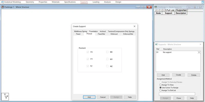
- Select support -> create -> pinned
- Select the restraint and click add
- Then assign it by assignment method option.
- Name any five topics that you will include while creating DBR.
Answer:
- In Design Basis Report the following topics can be included,
- Introduction -Location and type of the project
- Soil type and foundation details
- Structural layout
- Design data with reference to the code specification
- Load calculations
- Describe the term “Multi material design” of STAAD Pro.
Answer:
The term "multi-material design" of STAAD Pro defines the structure that is designed by implementing more than one structural material.
- Name the structure systems in STAAD Pro? Explain each system?
Answer:
SPACE - A 3D framed structure with loads applied in any plane. This structure type is the most general.
PLANE- This structure type is bound by a global X-Y coordinate system with loads in the same plane.
TRUSS- This structure type consists of truss members which can have only axial member forces and no bending in the members.
FRAME - A 2D or 3D structure having no horizontal (global X or Z) movement of the structure [FX, FZ, and MY are restrained at every joint].
- Explain the coordinate system adopted in STAAD Pro software.
Answer:
The coordinate system adopted in STAAD Pro software ARE,
- Global coordinate system
- Local coordinate system
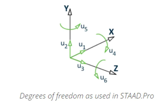
Global coordinate system:
- This coordinate system is a rectangular coordinate system (X, Y, Z) which follows the orthogonal "right hand" The global coordinate system defines the position and translation of a body in space.
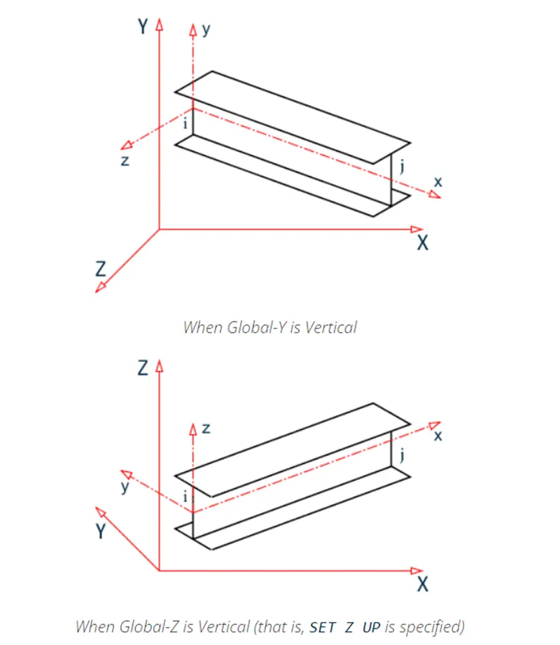
- Local coordinate system:
- Local coordinate systems define how limbs and body segments articulate about joints.
- Elaborate DBR and its uses.
- A DBR is a document that outlines the key points of a proposed engineering project. It is typically used to communicate the project's goals, scope, and requirements to stakeholders. The report should also include a feasibility study and cost analysis.
- Uses:
- It gives the detailed summary of the project
- Helps in easy understanding between stakeholders.
- It can be like check list for the materials and time line.
- Explain the different types of analysis options in STAAD pro.
Answer:
The different types of analysis options in STAAD pro. Are,
- P-delta analysis
- Geometric non-linear analysis
- Pushover analysis (Static-Non Linear Analysis) or a buckling analysis.
P-delta analysis
- P-delta effect in Staad, it is important that the vertical and horizontal load cases be combined under one single load case.
Geometric non-linear analysis:
- Geometric nonlinear analysis is a structural analysis method designed to verify the strength capacity of a structure, which accounts for both plasticity and buckling failure modes.
Pushover analysis
- "Push - over", push the building until you reach its maximum capacity to deform. It helps in understanding the deformation and cracking of a structure in case of earthquake and gives you a kind of fair understanding of the deformation of building and formation of plastic hinges in the structure.
- Explain the difference between Fixed and Fixed But condition:
Answer:
- Fixed condition in the STAAD Pro software is the condition where all the degrees of freedom that is horizontal or vertical or moment are fixedor we can say these conditions are restrained we cannot change accordingly.
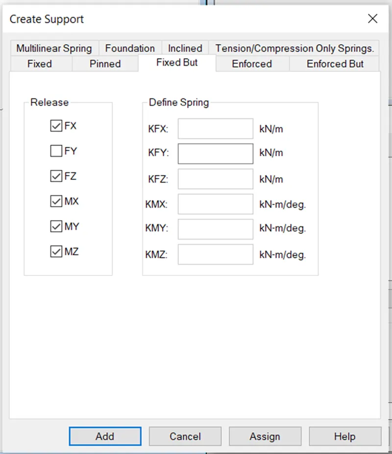
- The Fixed But support condition is used to allow the user to define which degrees of freedom of a node are free and which are fixed.
Practical
Aim:
To Create a STAAD Model with the following Specification
a. A beam of span 16m
b. Support: Fixed on one end and Roller support(Horizontal) on the other end
c. A point load of 50 kN at the mid-point
d. Draw SFD and BMD using software
Procedure:
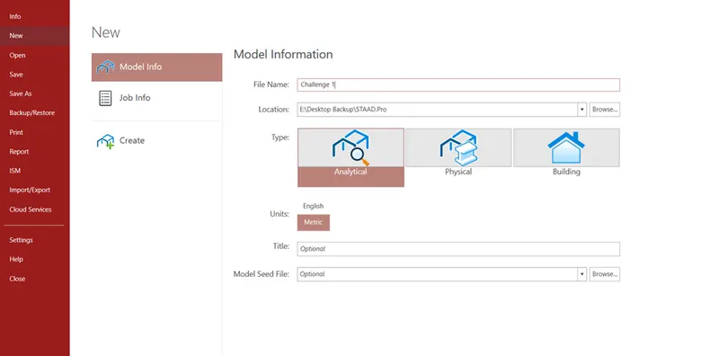
- Open the STAAD PRO software
- Enter the information
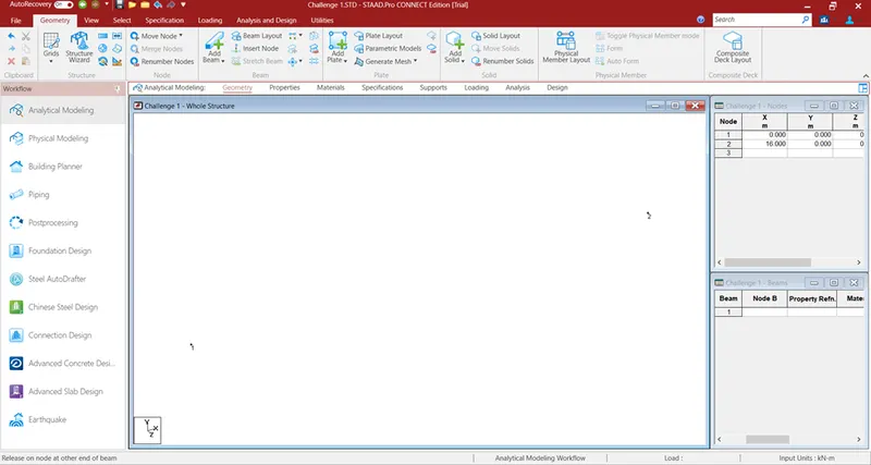
- Creating Node:
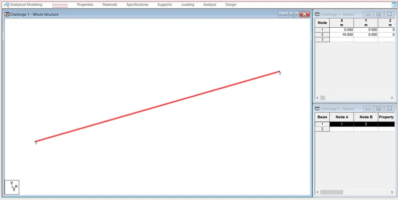
- Go to Geometry tab -> enter the node distance in the node window
- Creating Beam:
- Right click -> add beam -> select node points 1 and 2
- Assigning supports:
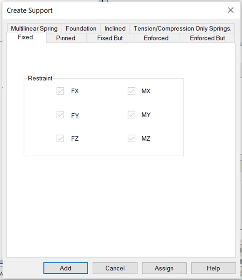
- Go to supports -> click create button
- Create a support for fixed
- Then create a support for roller by selecting the below option
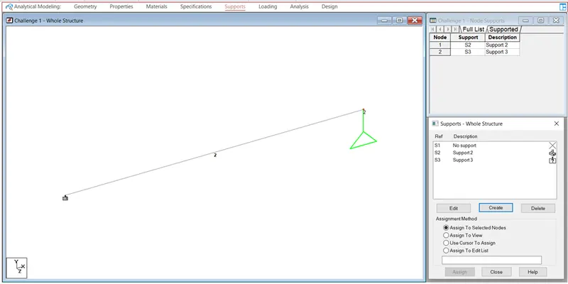
- Then pick the node and assign it to the fixed on one end and roller on the other end.
- Assigning property:
- Go to properties -> Define -> rectangle and select concrete and enter the dimension -> add
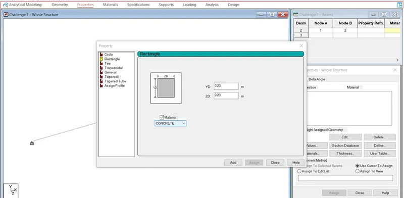
- Select the property and assign it by use cursor to assign it option
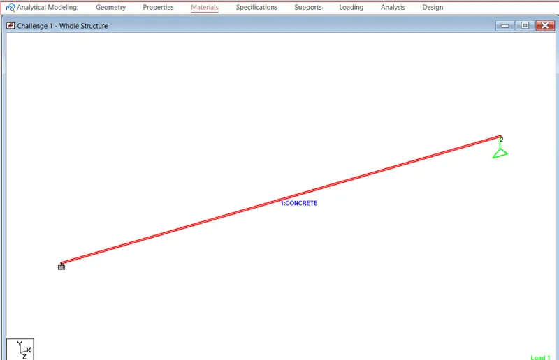
- Assigning load:
- Create a load case by clicking add
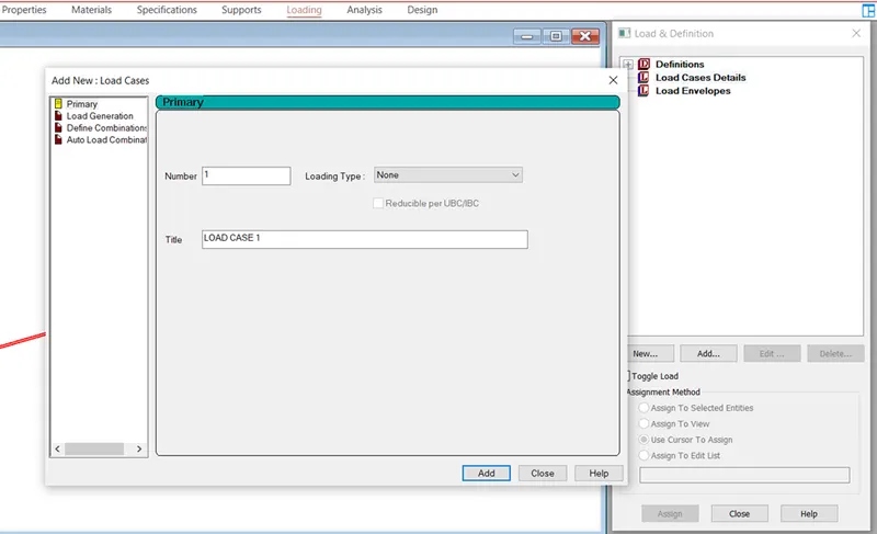
- Select the load case and go to concentrated force and enter the load and dimension from end as follow.
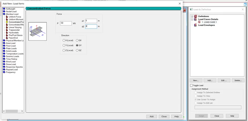
- Assign the load by use cursor to assign
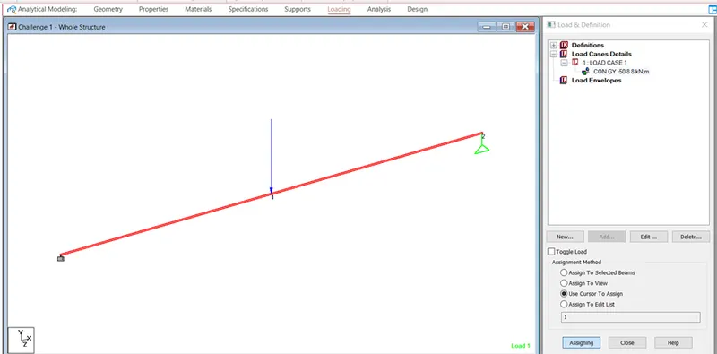
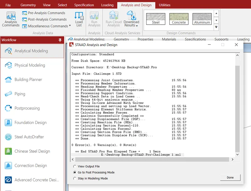
- Run analysis:
- Select Analysis and design -> run analysis

- Read the output and rectify the error if any.
- SFD and BMD:
- Select FY for shear force
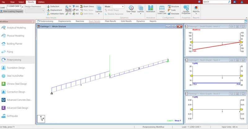
- Select MZ for bending moment
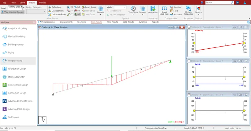
- Select displacement to see the displacement result
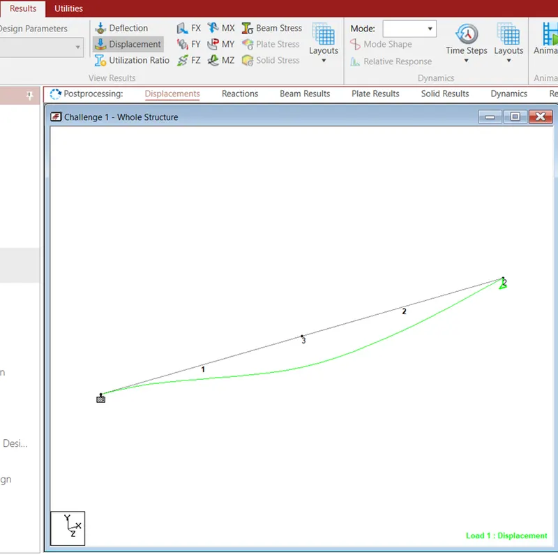
- Result:
- Hence the beam is created with the above conditions