Week 1 Challenge
- 1.
- Select STAAD Import from the backstage.
The Import from STAAD.Pro dialog opens.
- Click [...] in General settings to browse and select a STAAD.Pro (*.std) file to import.
- Select Use Mapping File in Section Mapping settings, and then click [...] to browse and select a mapping file to import.
Note: Mapping files are delivered with AECOsim Building Designer, and are named using analysis program names. Their function is to compare two lists of section data, and to map the STAAD.Pro sections to the corresponding sections in AECOsim Building Designer. They are located in the active configuration \\Configuration\Datasets\[active dataset]\Datadata folder
- Set the catalog type and catalog instance assignments for the imported member types. This data is used by AECOsim Building Designer to rebuild the members' structural data as defined in the structural member catalogs.
- In Steel settings, select a section definition that is to be designated as the Default Section Name. This section definition is applied to imported members whose section data is not available in AECOsim Building Designer.
- Check Verify to scan the imported file for unknown sections.
The Unknown Sections dialog appears providing an opportunity to write the unknown sections to the active XML section definition file before importing.
- In Revision Tracking, check Use Design History. Design History tracks changes to a DGN file. Viewing details about the revision by using the controls on this tool.
- Click Import.
The update design dialogue appears. Review detailed information about each imported member and select which ones you want to import before accepting them into the target DGN file.
Note: Update Design Results contains Load Case and Load Combination data imported from the STAAD.Pro (*.std) file. - Click Update to complete the import process.
The structure is updated.
2. Different material that can be designed using STAAD.PRO are below]
- steel
- concrete
- Timber
- Aluminium
- Stainless Steel
- Steel 36 KSI
- Steel 50_KSI
- Steel 275 N/mm2
- Steel 355 N/mm2
- Q235
- Q460
- Q255
3. 1) Right-click on the analytical model screen
2) then from the list box click on the picture taken
3) then paste the picture anywhere in the desired document
4. THree ways in which we can make a model file
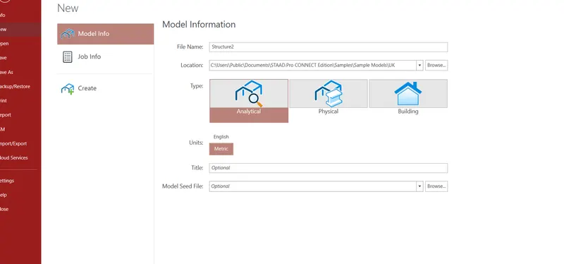
this is one of the way to create a model
click new 'thenn click new model or create
with assigning the suitable units
5. 1. first create a beam or column in the analytical model
2. then click on properties ribbon in the STAAD PRO SCREEN
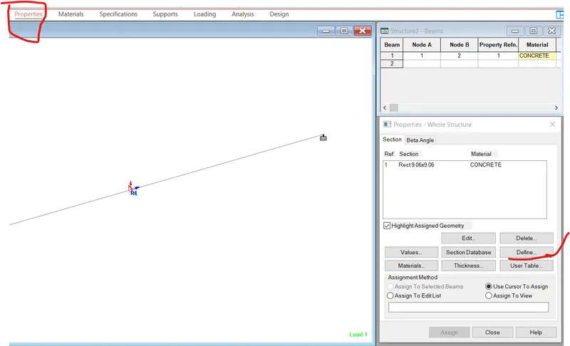
3. Then define the properties of the element as shown above whether it is rectangular or circular along with the dimensions.
question 2.
1. Six design parameters involved in RCC Design
Deflection check
Clear Cover
maximum allowable depth
ultimate tensile strength of steel and concrete
Limiting tensile strength of steel and concrete
Lateral buckling
Torsional Buckling
2. Different cursor types
Nodes cursor
Beam Cursor
Column Cursor
Plate Cursor
Load
Members cursor
Geometry cursor
3. different views for model
a) Firstly Right click on the model screen
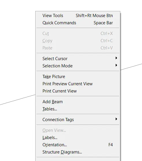
Then this list is appeared then click on the view tools . or press shift+ right button
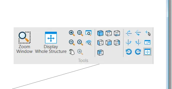
Then this toggle will be displayed click on each view to see the front or bottom or right and left view
4. Simply Supported Condition
First, create a beam with the help of nodes of any arbitrary length
NOW from the support ribbon open it now define the supports or create the supports
now create the two hinged supports and apply to the beam as shown below
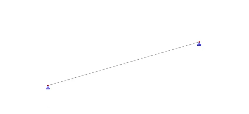
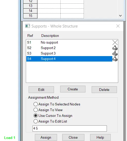
support 4 and support 2 are used
5.
DBR
1) planning
2) codal provisions
3) Design Methodology
4) contents of the building
5) Detail Design and analysis
6. Multi-material design
Multi-material design is design using different materials. any building or structure is made with the help of the multi-materials like steel, concrete or aluminum.
3.
1
A STRUCTURE can be defined as an assemblage of elements. STAAD.Pro is capable of analyzing and designing structures consisting of frame, plate/shell, and solid elements. Almost any type of structure can be analyzed by STAAD.Pro.
SPACE
PLANE
TRUSS
FLOOR
A 2D or 3D structure having no horizontal (global X or Z) movement of the structure [FX. FZ. and MY are restrained at every joint) The floor framing (in global X-Z plane) of a building is an ideal example of a this type of structure. Columns can also be modeled with the floor in a FLOOR structure as long as the structure has no horizontal loading. If there is any horizontal load, it must be analyzed as a SPACE structure.
Specification of the correct structure type reduces the number of equations to be solved during the analysis. This results in a faster and more economic solution for the user.
2.
1. Global coordinate system
2. Local coordinate system
Global coordinate system
The Global coordinate system is an arbitrary coordinate system in space which is utilized to specify the overall geometry & loading pattern of the structure.
Conventional Cartesian Coordinate System
This coordinate system is a rectangular coordinate system (X, Y, Z) which follows the orthogonal right hand rule. This coordinate system may be used to define the joint locations and loading directions.
Cylindrical Coordinate System
In this coordinate system, the X and Y coordinates of the conventional Cartesian system are replaced by R (radius) and a (angle in degrees). The Z coordinate is identical to the Z coordinate of the Cartesian system and its positive direction is determined by the right hand rule
Reverse Cylindrical Coordinate System
This is a cylindrical type coordinate system where the R- plane corresponds to the x-Z plane of the Cartesian system. The right hand rule is followed to determine the positive direction of the Y axis.
Local coordinate system
A Local coordinate system is associated with each member (or element) and is utilized in MEMBER END FORCE local load specification,
Each axis of the local orthogonal coordinate system is also based on the right-hand rule. Note that the local order
system is always rectangular. A wide range of cross-sectional shapes may be specified for analysts. These include red the shapes prismatic shapes etc
3. DBR AND ITS USES
To specify and compile the data required for analysis and design of structural elements of the project.
clearly depicts the assumptions and specificationsthat are being used to develop the construction documents for a project.
it will also help avoid the scope creep that can derail the project schedule and lead to budget overruns.
USES
1) planning
2) codal provisions
3) Design Methodology
4) contents of the building
5) Detail Design and analysis
4. perform analysis
PDeltaAnalyisis
buckling analysis
direct analysis
generate floor spectrum
Nonlinear analysis
Imperfection analysis
pushover analysis
5.
fixed and fixed but
in the fixed command we have all the desgree of freedom is restrained. it means all the moments and forces are applied. and structureis static
and in fixed but we can release the forces or moments to have some degree of freedom for the structure
as shown below
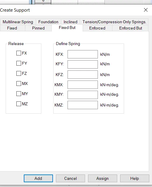
Practical
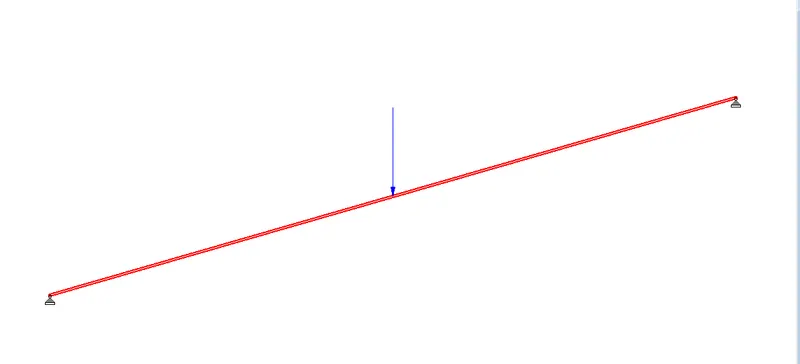
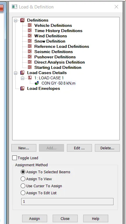
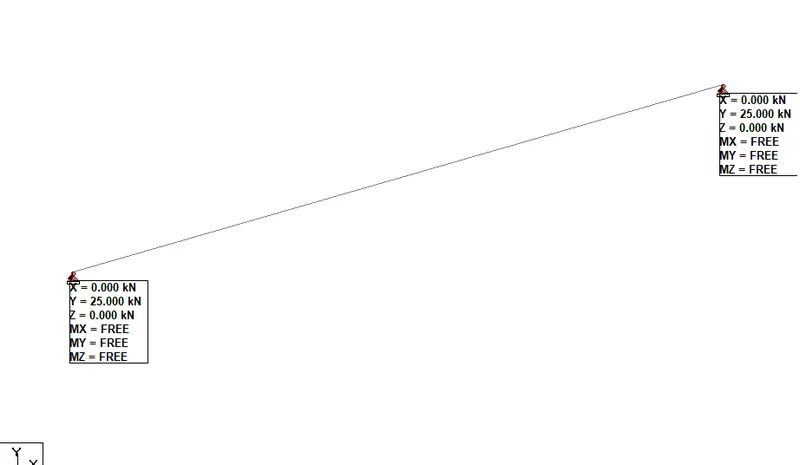
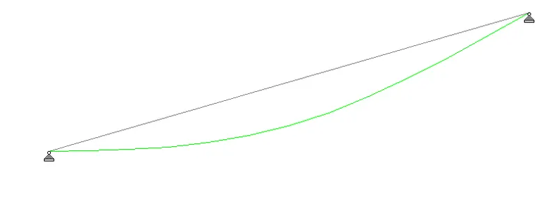
Deflection
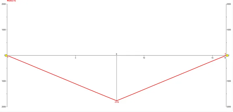
BMD
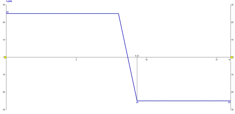
SFD
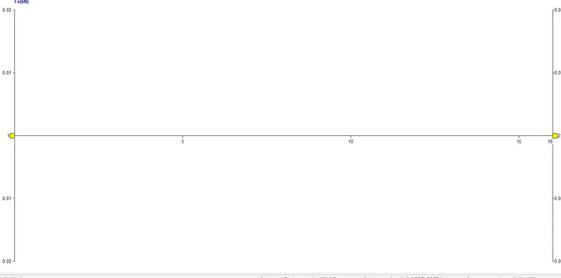
AXIAL FORCES
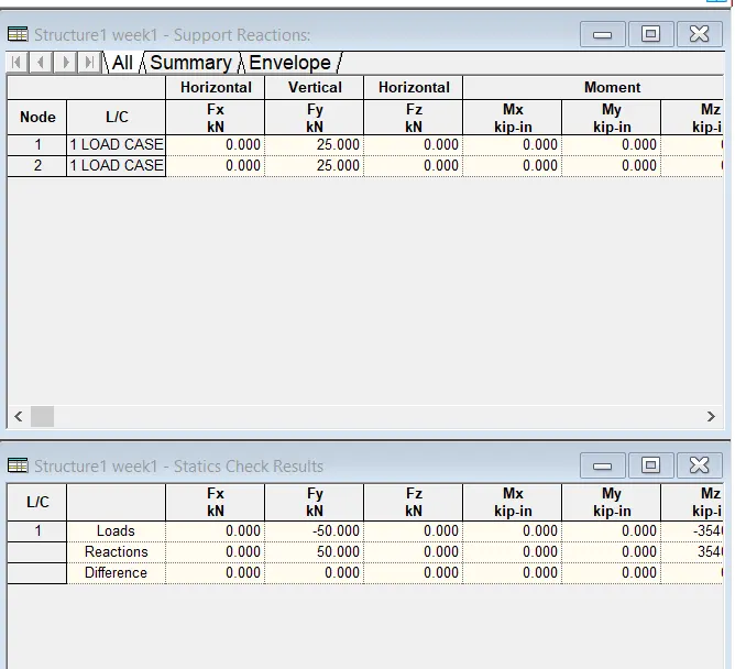
RESULTS
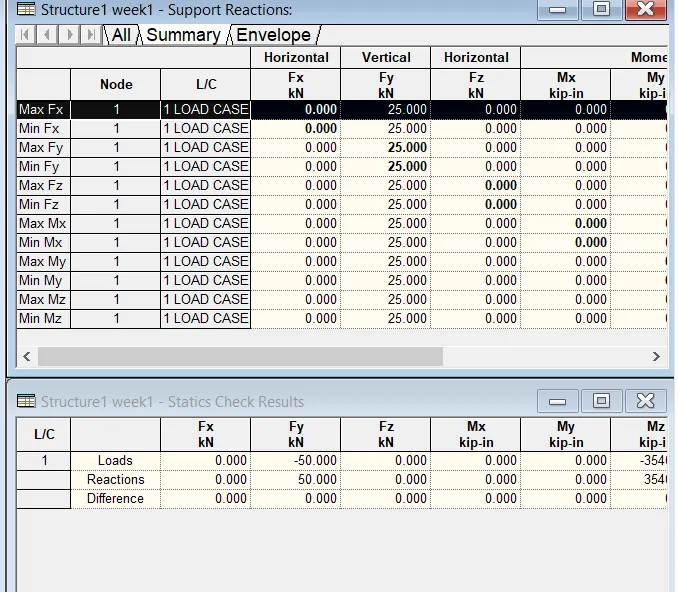
LOAD RESULTS