Week 1 Challenge
1 i,
Introduction
STAAD.Pro CONNECT Edition includes a new Ribbon-Based Graphical User Interface. All the STAAD.Pro V8i tools/commands are available in STAAD.Pro CONNECT Edition, but through the Ribbon, the tools are organized in a very logical, workflow-based layout. Through this course, we will walk you through the new graphical user interface to help you maintain your productivity while upgrading to STAAD.Pro CONNECT Edition.STAAD.Pro CONNECT Edition includes a new Physical Modeling Workflow. Through the Physical Modeler, you can model structural elements as they will be physically constructed, allowing you to model elements such as girders, multi-story columns, and slabs/walls quickly and accurately. (STAAD.Pro V8i includes an Analytical Modeling Workflow only.) Through the STAAD.Pro CONNECT Edition Physical Modeler, we can transfer data between STAAD.Pro, ISM (Integrated Structural Modeler), and a BIM application to increase your productivity in creating accurate construction documents. Structural members, such as beams/columns/braces, concrete walls, and concrete slabs can be transferred into the STAAD.Pro Physical Modeler from ISM and from ISM into the STAAD.Pro Physical Modeler. Through this course, we will introduce you to the new workflows that are available for integration between ISM and STAAD.Pro CONNECT Edition.
PROCEDURE:
Open the software Staad pro
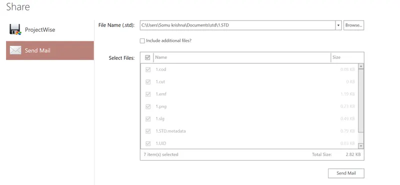
Click on the share icon
Click on and then send mail
Browse the file we want to share
ii,
The materials that can be designed by using Staad pro are
Aluminium
Concrete
Steel
Stainless steel
iii,
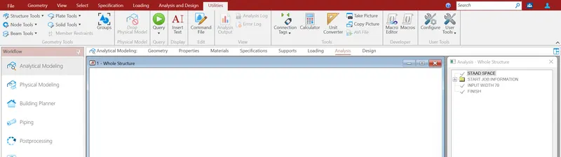
Yes it is possible to capture the images in the stadd.pro
iv,
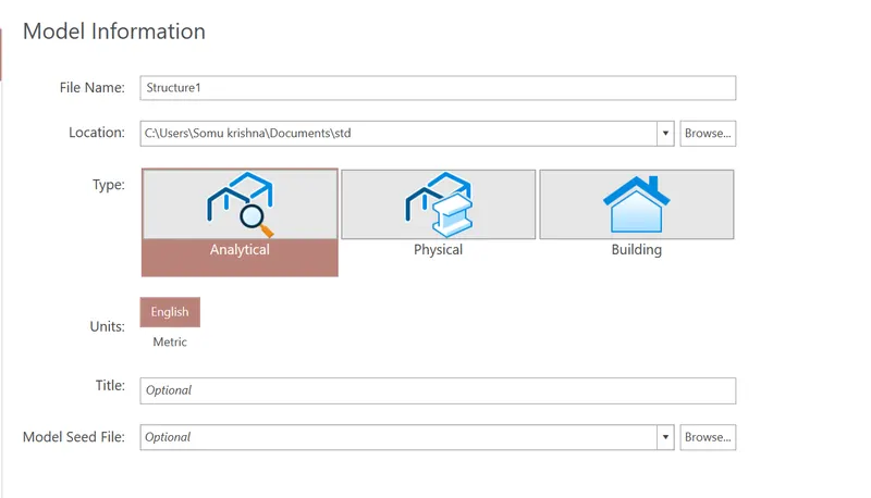
Analytical model
Physical model
Building model
These are the three models to create in the satdd.pro
v,
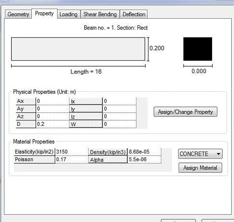
Open the property in geometry
Go to Define the material
Select rectangle
Give the dimensions
Select material type is concrete
Assign the property to the material.
2
i,
The six design parameter involved in RCC design are:
Clear cover
FC compressive strength of concrete
FY tensile strength of steel
Maximu Minimum diameter of the bar
Code of practice
End concrete design
ii,
Node cursor
Beam cursor
Plate cursor
Surface cursor
Solid cursor
Plate and solid cursor
Geometric cursor
Physical membrane
iii,
Top view
Back view
Right view
Left view
Front view
Bottom view
Isometric view
iv,
Go to the support command in the tool pallet command
Click on create support command
There we can get option like fixed support, pin support, fixed but , enforced but , cable support, inclined support
v,
DBR Design basis report
To take up a project from the scratch to the end, its needed
To specify the data and compile data received and analysis and design of structural element
It contains the assumption and specification to develop the project
It will help to avoid the scope and the creep that can lead to budget overness
Contains the general column drawing
Contains the project planning
vi,
Staad pro supports several steel, concrete and timber material in a separate member
This separate member will coordinate and the formed in to a structure
3
i,
They are four structural system inStadd.pro
| STRUCTURE SYSTEM LOADING | DEFORM | GEOMETRY | JOINT |
| Plane 3D | 3D | 3D | ANY |
| Space 2D | 2D | 2D | ANY |
| Frame parpen to XZ | Parpen to XZ | 2D | ANY |
| Truss 3D | 3D | 3D | PINNED |
ii,
Gloabal Axis - Global Axis is fixed in the coordinate system
Local Axis - Local Axis is variable and is used for the orientation of the beam with the load variable
iii,
DBR Design basis report
To take up a project from the scratch to the end, its needed
To specify the data and compile data received and analysis and design of structural element
It contains the assumption and specification to develop the project
It will help to avoid the scope and the creep that can lead to budget overness
Contains the general column drawing
Contains the project planning
iv,
v,
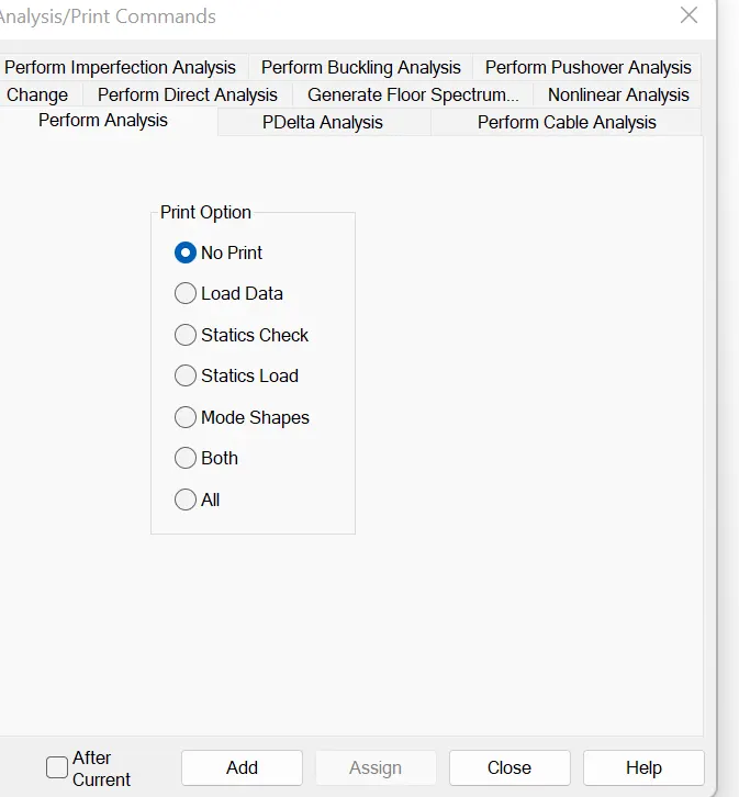
Fixed supports can resist vertical and horizontal forces as well as a moment. Since they restrain both rotation and translation, they are also known as rigid supports. This means that a structure only needs one fixed support in order to be stable. All three equations of equilibrium can be satisfied..The Fixed But support condition is used to allow the user to define which degrees of freedom of a node are free and which are fixed. For example, Pinned support is equivalent to Fixed But MX MY MZ (no movement allowed, rotation allowed). When the FIXED or FIXED BUT type of support is specified, for those degrees of freedom which are to be treated as fully restrained, STAAD assumes the displacements to be known quantities whose value is zero. Hence, those degrees of freedom are not considered for the stiffness matrix, and their value is not calculated. (For the FIXED BUT support type, if any degrees of freedom are assigned a spring using the KFX thru KMZ terms, those are treated as unknowns and their displacements are calculated).
Aim
To create the beam of span 16 m and then with the fixe end conditions
Introduction
STAAD.Pro CONNECT Edition includes a new Ribbon-Based Graphical User Interface. All the STAAD.Pro V8i tools/commands are available in STAAD.Pro CONNECT Edition, but through the Ribbon, the tools are organized in a very logical, workflow-based layout. Through this course, we will walk you through the new graphical user interface to help you maintain your productivity while upgrading to STAAD.Pro CONNECT Edition.STAAD.Pro CONNECT Edition includes a new Physical Modeling Workflow. Through the Physical Modeler, you can model structural elements as they will be physically constructed, allowing you to model elements such as girders, multi-story columns, and slabs/walls quickly and accurately. (STAAD.Pro V8i includes an Analytical Modeling Workflow only.) Through the STAAD.Pro CONNECT Edition Physical Modeler, we can transfer data between STAAD.Pro, ISM (Integrated Structural Modeler), and a BIM application to increase your productivity in creating accurate construction documents. Structural members, such as beams/columns/braces, concrete walls, and concrete slabs can be transferred into the STAAD.Pro Physical Modeler from ISM and from ISM into the STAAD.Pro Physical Modeler. Through this course, we will introduce you to the new workflows that are available for integration between ISM and STAAD.Pro CONNECT Edition.
PROCEDURE:
Open STAAD.pro Connect Edition
Go to Grids - Beam grids
To create the span 16m length in the stadd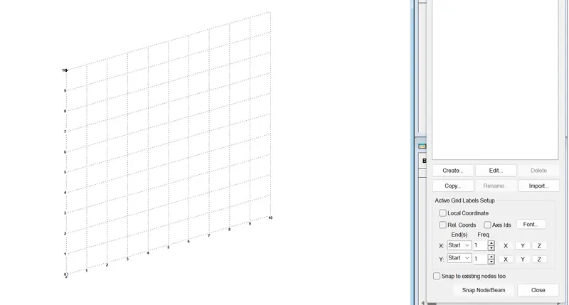
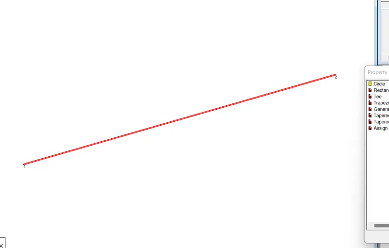
For the view of two nodes
Right click - labels - assign nodes
AIM
ii,
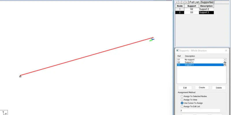
Support : Fixed on one end and Roller support(Horizontal) on the other end
Go to Support-Create
Adding Fixed support and roller support horizontal on the other end
Use cursor to assign
AIM
iii,
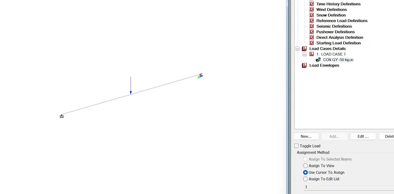
A point load of 50 kN at the mid-point
Go to Loading- Load cases details-Add -Dead load
Select dead load -Add -Self load
Select dead load - Add-Member load -Concentrated load of - 50
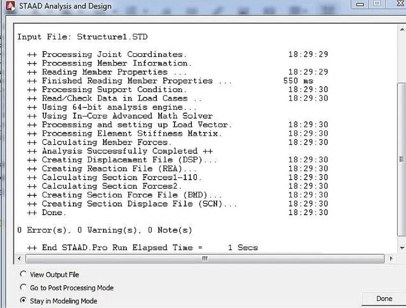
Go to Analysis>Run Analysis
AIM
iv,
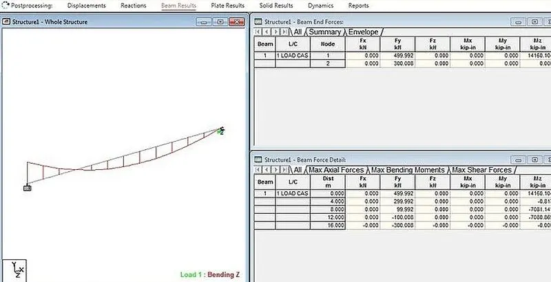
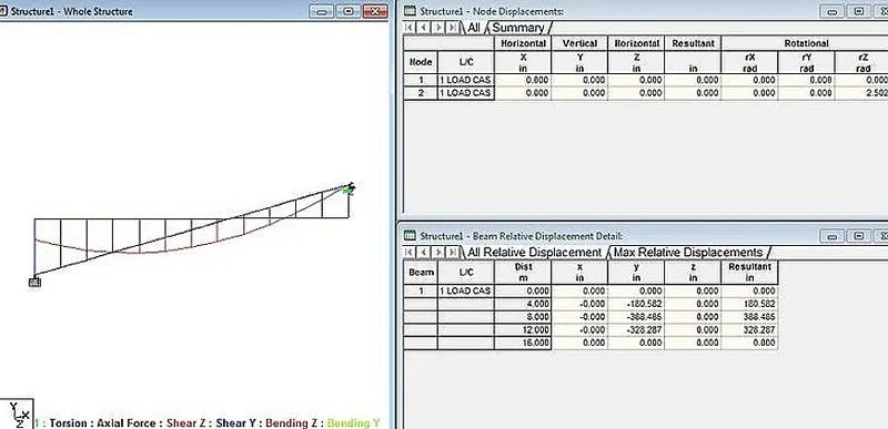
Draw SFD and BMD using software
To view the Bending Moment Diagrams, select the Beam page from the left side. From the top menu bar, choose Results - View value. Under Ranges, choose All. (The All button means the Bending moment diagram will be displayed for all members.)
Under the Beam Results tab, you will see the options Bending, Shear, Axial, Displacement and Stresses.
Make the appropriate choice.
Click on the Annotate button. Then click on the close button.
Here are a group of of other options to view BMD, SFDs
To view the bending moment diagram for individual members you may go to the Beam - Graphs page on the left and click on any member and the BMD, SFD and axial force diagrams for the member would be displayed on the right