Week 1 Challenge 2
AIM
To compare the performance of 3 different types of beams under a bending load.
THEORY
When a bending load is applied to a beam, it experiences a bending moment which causes change in its shape and development of internal stresses. The material is in compression on the inside of the curve and in tension at the outside of the curve. The transverse planes in the material remain parallel to the radius during bending.
Finite element analysis (FEA)
It is an application of finite element analysis (FEM) for solving structural problems. A problem is solved by subdividing a larger system into smaller and simpler parts called finite elements. This is implemented by construction of a mesh of the object, the numerical domain for the solution with finite number of points. A typical procedure followed for the same includes dividing the domain of the problem into collection of sub-domains, each represented by a set of element equations to the original problems followed by systematically recombining all sets of element equations into a global system for final calculations.
FEA helps in analyzing problems over complicated domains when the domain changes, desired precision varies over entire domain or when the solution lacks smoothness. It removes various instances of creation and testing of hard prototypes during the design process with the help of computational software.
Cantilever beam
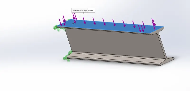
A cantilever is a rigid structural element which extends horizontally and is supported at one end only. In this project, we have considered each beam to be a cantilever beam with uniform loading at one of the face. The material applied to each beam is alloyed steel and a load of 1500N is applied at the smaller face of each beam.
PROCEDURE:
Creating the geometry in SolidWorks.
. After creating the geometry, extrude it to 400mm.
• Under Simulation, perform a new study for static analysis.
• General steps in FEA problem:
• PRE-PROCESSING: -
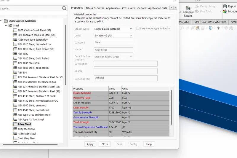
Defining material property. Here we have defined the material for each beam to be Alloy steel.
o SOLVING: -
Types of Analysis: Static Analysis
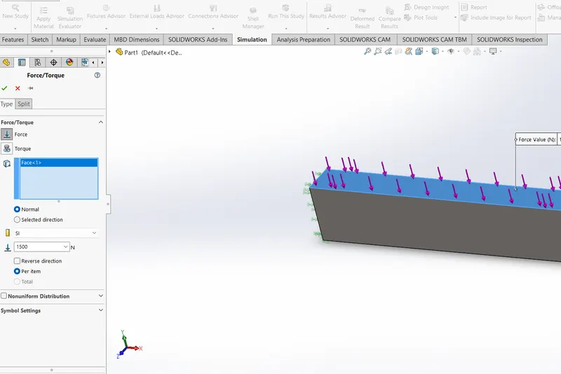
• Beams are fixed at one end of the extrusion along the cross-section.
▪ A 1500Nload was applied over the top face
• The Simulation was run using after refining mesh for good results.
CASE1
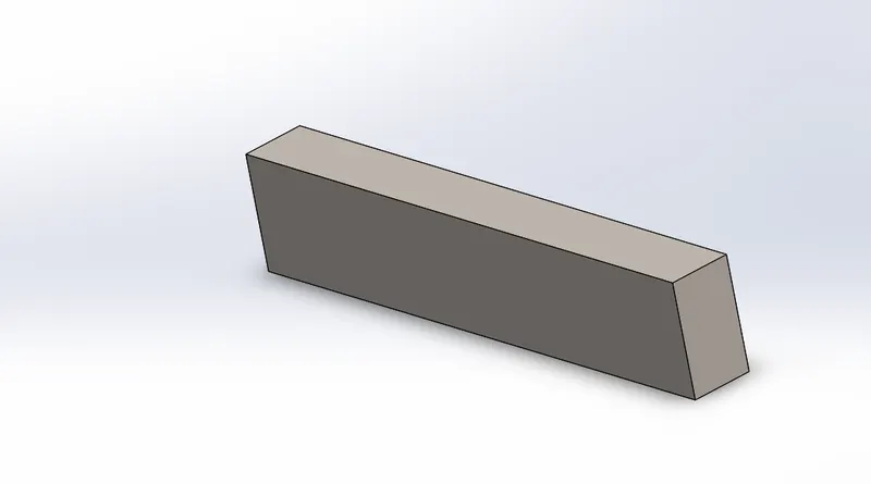
build as per dimensions
assign material to all the cases
fixing at one end and applying force at smaller face
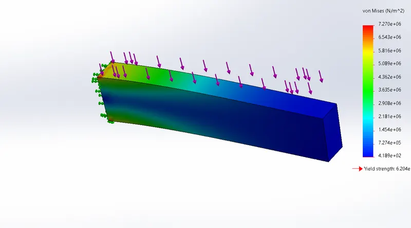
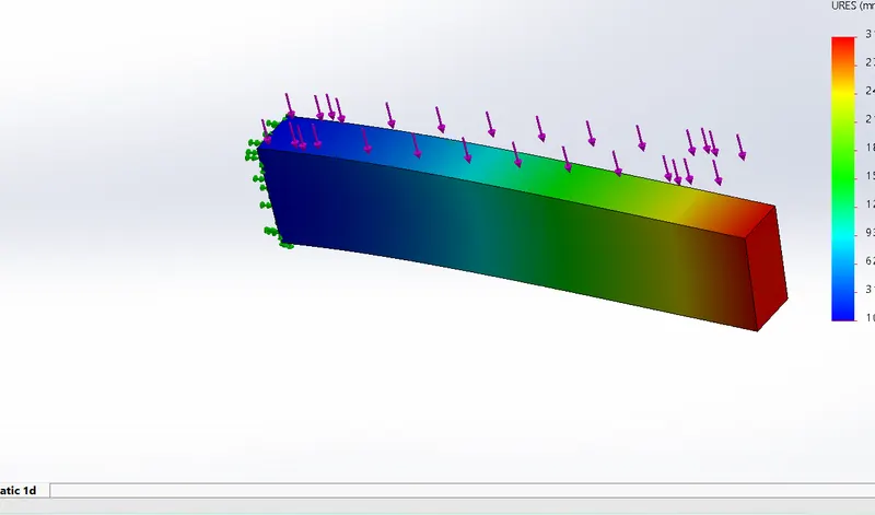
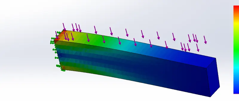
results of case1
stress
displacement
strain
 .
.
for case2 repeat the same steps according to given dimensions
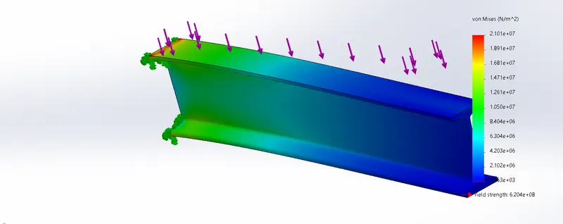
results for case2
stress
displacement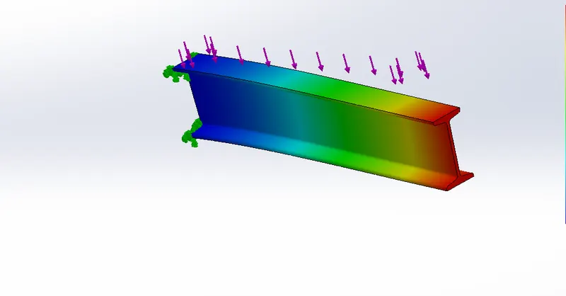
strain
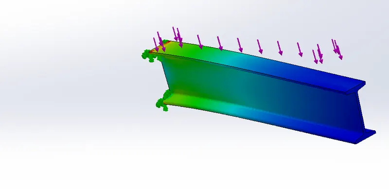
for case3 too repeat the same steps by constructing the model as per given dimensions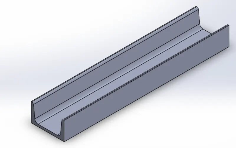
results for case3
stress
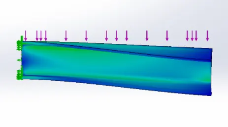
displacement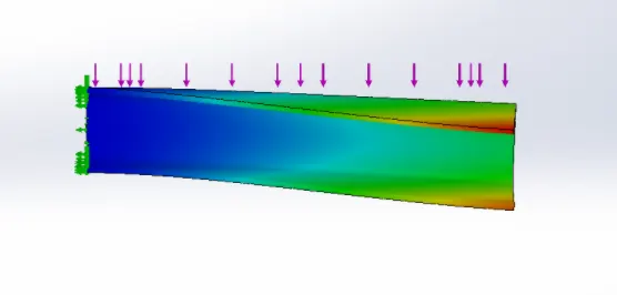
strain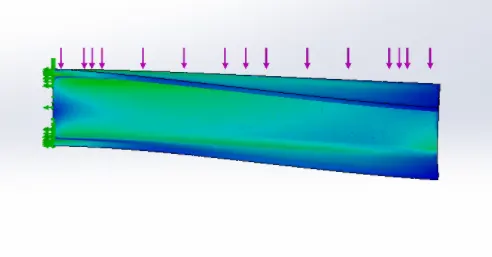
CONCLUSION:
1. For Beam of Rectangular Cross-section, the values of stresses, displacement and equivalent strain are minimum as compared to other beams. The factor of safety for the load applied is also maximum considering other bears. But the weight of the bearn is significantly higher than other cases.
2. For Beam of I Cross-section, the values of stresses, displacement, equivalent strain, factor of safety are in between to that of other two cases. The weight of the beam is minimum compared to other beams.
3. For Beam of Channel Cross-section, the values of stresses, displacement, equivalent strain, factor of safety are minimum of all three cases.
4. All these beams can be used for their respective purposes according to the requirement, aesthetics, cost. If the requirement is of resisting most of the bending moment, I section can be used over rectangular beam as it also serves it's purpose almost equally and it requires less material to construct and hence more economical compared to rectangular-section.
5. Moreover, from beam theory, it is well explained that for same weight and length of beams, the flexural rigidity of l-section is more than the flexural rigidity of rectangular section. Hence, I-section is a better choice for bending load.
6. When depths are same, where the full strength of I shaped beams is not needed, C-section beams are used as one can save steel equal to the area of one flange (= 2 half flanges). The I section of the same depth would have been under stressed and therefore underutilised. The channel section offers a clean and flat surface for the full depth, on one side, that greatly facilitates connections to other member besides being architecturally more pleasing /aesthetic.
7. Out of these three beams, if one has to choose for design purposes, I-section should be given first preference, then Channel-section (C-section) and then beam of rectangular-section.