2D Finite Element Meshing over sheet metal component ( Car Hood model)
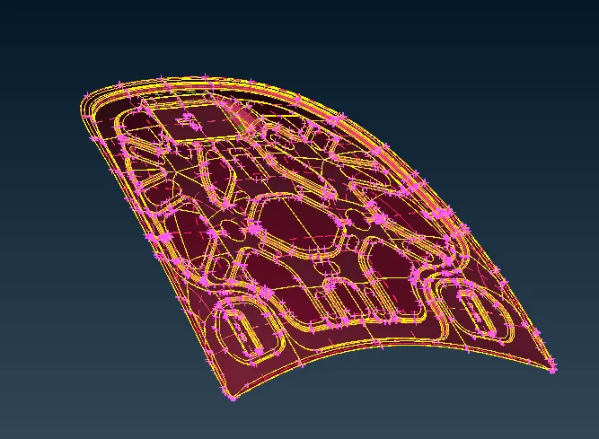
Aim:- To perform 2D Finite element meshing over the sheet metal component (Car Hood ).
Challenges:
1) The newly imported geometry consists of a number of errors.
2) Hard to visually find the numbers of parts present in the model itself.
3) hard to understand the actual shape of some features as the imported geometry is somewhat distorted due to the called out from another workbench (software)
Quality Criteria
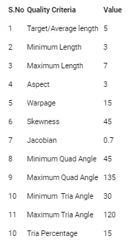
I had followed the Quality parameters which are mentioned in the above image.
Car Hood
A car hood also referred to as a bonnet in some other countries is the hinged cover that rests over the engine of a front-engine vehicle. Its purpose is to provide access to the engine for repair and maintenance. Car hoods are typically constructed from steel and sometimes from aluminum.
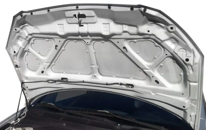
Concerns regarding the severity of a potential pedestrian head injury during a collision with a motor vehicle have led to advanced hood designs on many models. Such designs may include a multi-cone inner hood panel design. An active structure that is capable of pushing the surface of the hood away from the vehicle's hard motor components in the event of a pedestrian crash is also in use. Also during the frontal impact along with the vehicle BIW body the hood is the first who comes into contact, so the hood should be designed in such a way that it will be deformed during such high impact event by absorbing impact energy very well and save the occupants.
The complete hood has three main components and held together with very Strong Industrial Adhesive. The first component is the Outer extract which we can see from the outside and have a more esthetic look to please the consumer and match the car design. the second one is inner extract as you can see in the image which contains several strengthing features on it. Its main task is to provide the necessary strength to the whole assembly. The third one is fixed in between those two Inner and Outer Extracts and known as a latch. The sheet-metal forming process is used to make a hood.
Steps:-
1) After importing the model the first thing I did is perform topo (Topology). You can find this option inTopo module in the Face section.
The topo just eliminates the un-necessary geometrical distortion in the model.
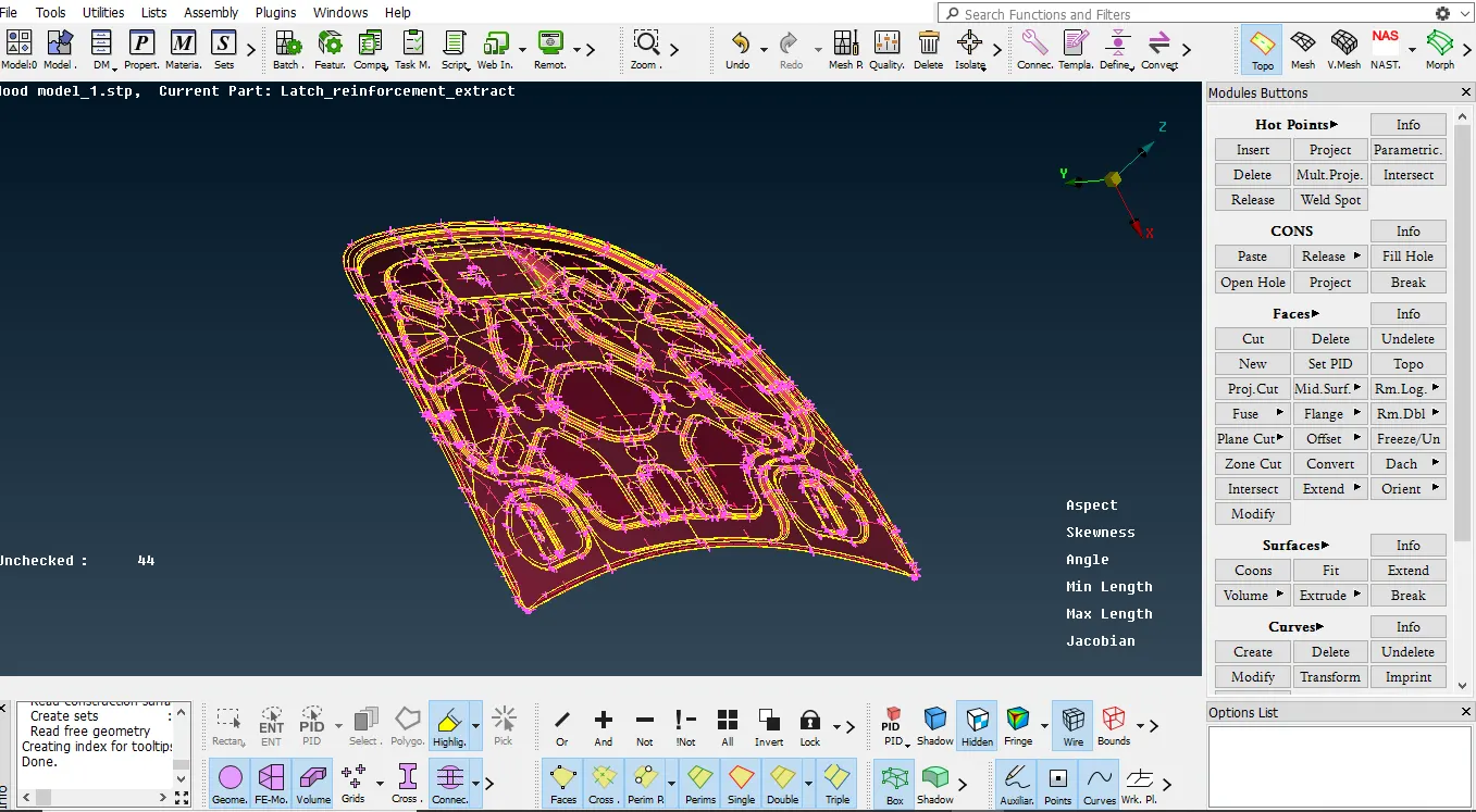
2) The second important thing is to identify how many parts are in the assembly/model.
by checking the properties of geometry we can get an idea about the number of parts in an assembly. In this way, we can separate out the parts/geometries that are hidden between two parts.
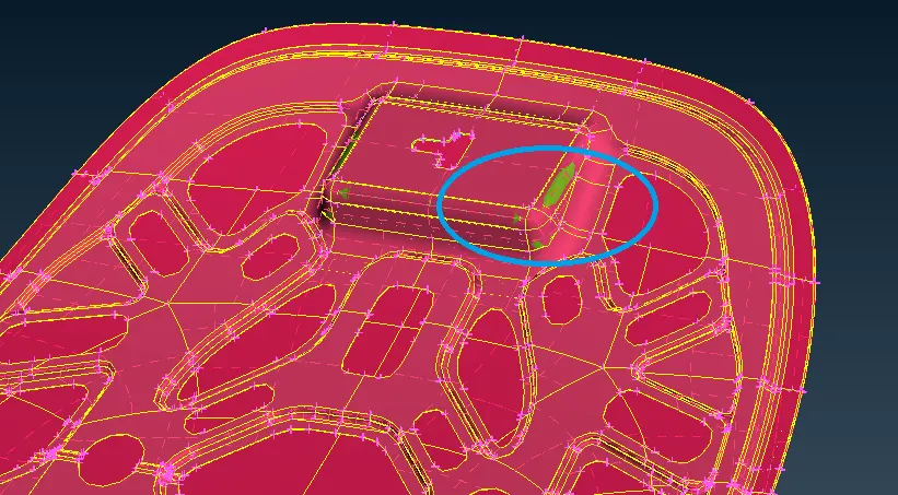
here as you can see the latch is in-between the outer and inner body it's hard to identify by just seeing it in some complex geometry.
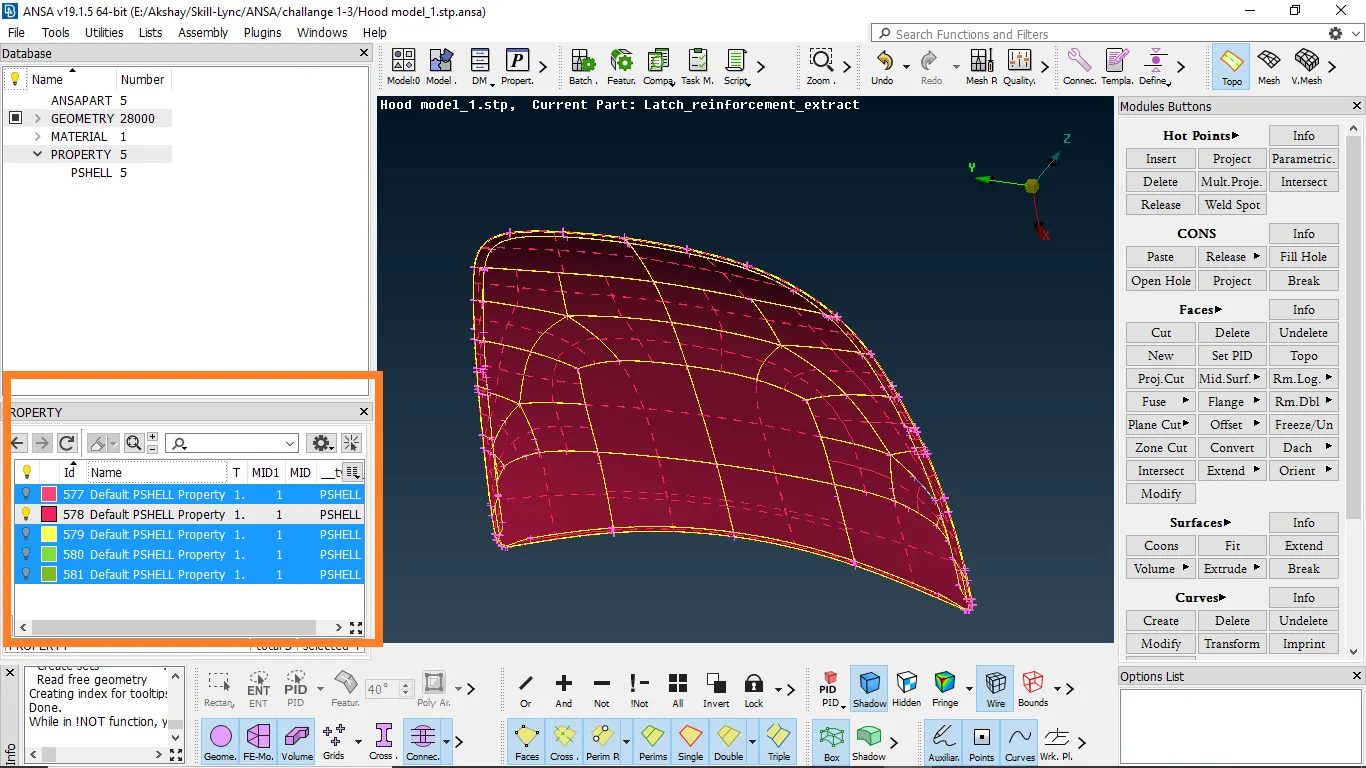
Here I separate out the outer body by hiding all other geometries. After that, I just save this view as a separate lock view with measured thickness.
In this manner, I separated all five parts and differentiate parts with different thicknesses and save it as a separate lock view so can work on them separately.
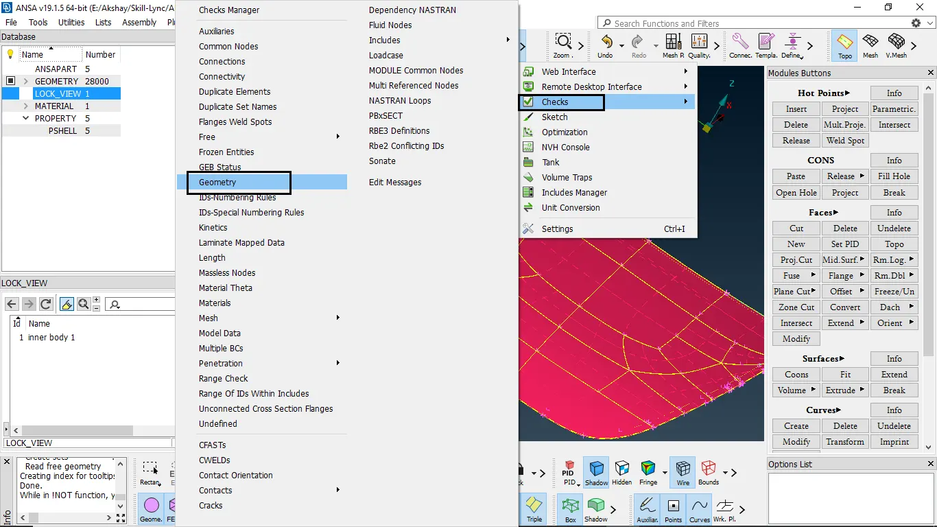
3) After that I open the geometry on which I want to work, In this case, the hood outer body and perform a geometry check to identify the errors in the body.
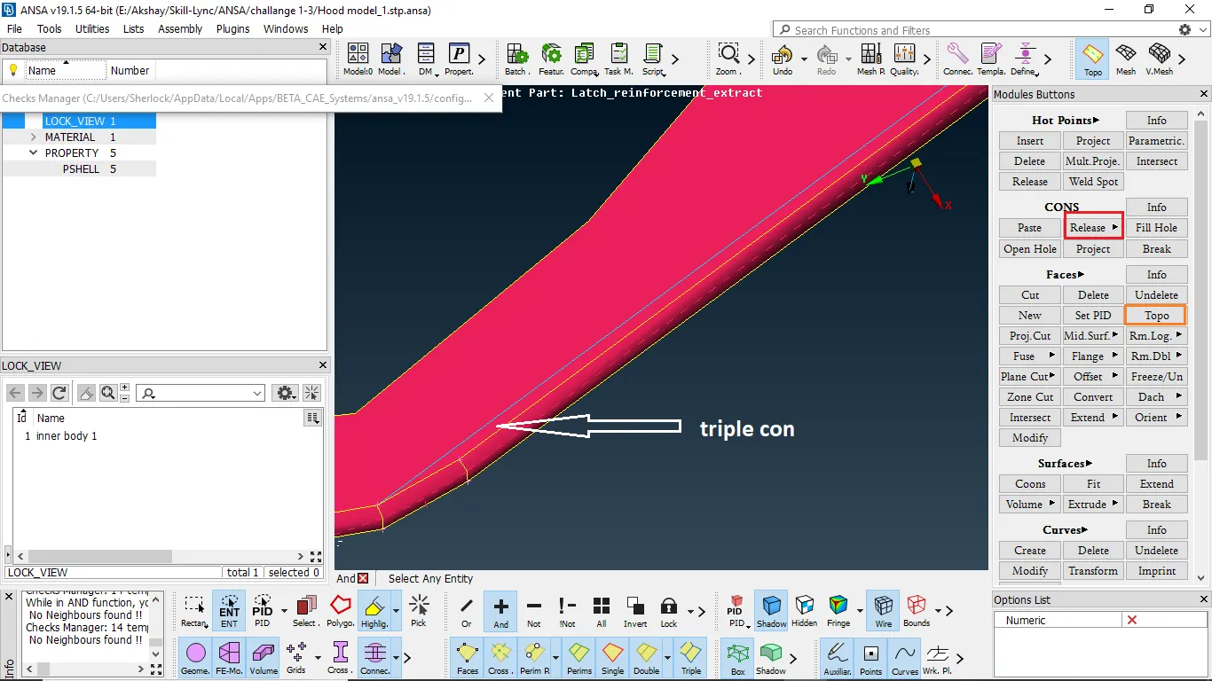
I get plenty of errors on this plate only, as you can see in the below image. Triple con error (occurs when more than two surfaces are stitched together )
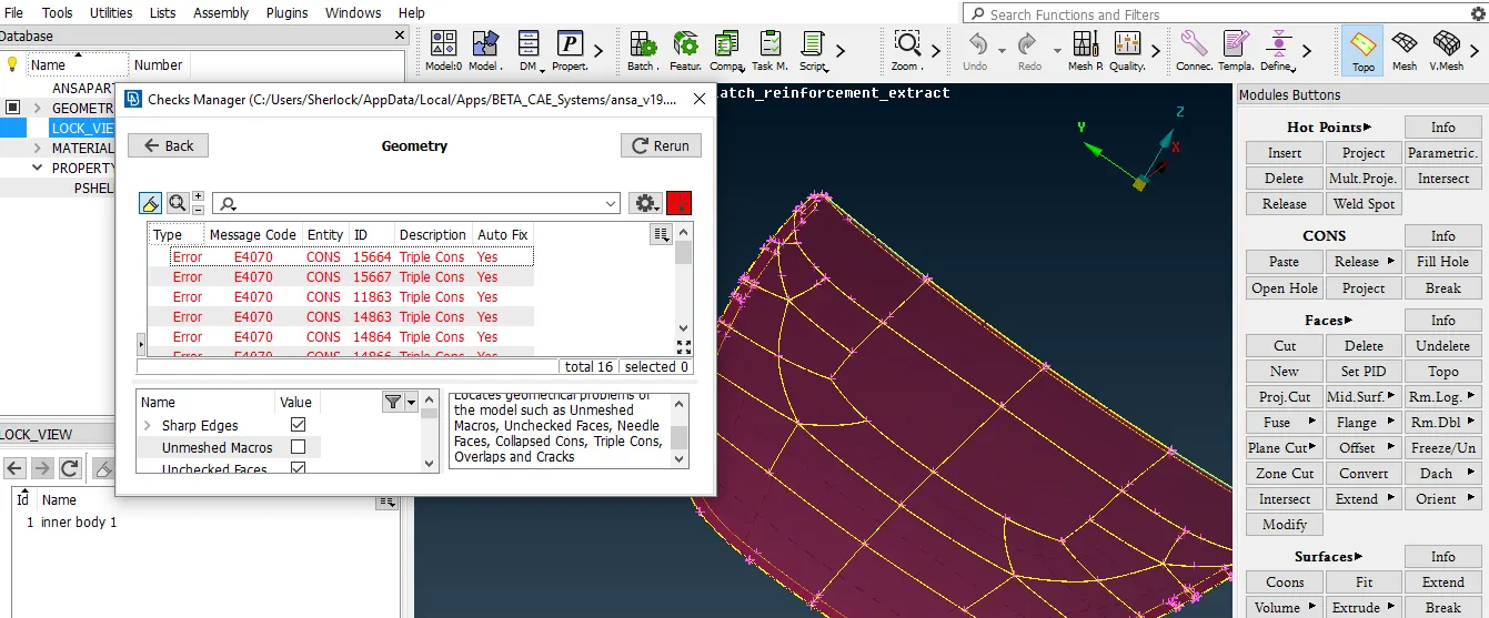
the majority of errors showing triple con so the next step is to remove that errors.
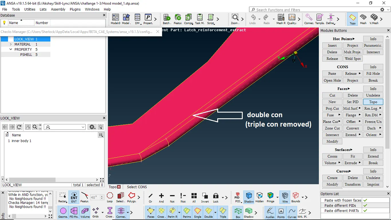
4) For this, I right-click on the error and click on the show only, this way I can able to see the part where the error is located. (I tried show option also but with that its hard to locate where is error exactly) After that, I called the neighboring element to that specific errored surface and performed release and topo on that to remove that error.
After successfully did the release the triple con and stitch it by topo I get the result like shown in the below image.
5) Performed the same geometry clean up on other sheet metal parts also. the error I get is as follows,
a)Triple con:- As explained in the above example
b)Needle Face:- These are the small surfaces generated in the model to satisfy the geometry.
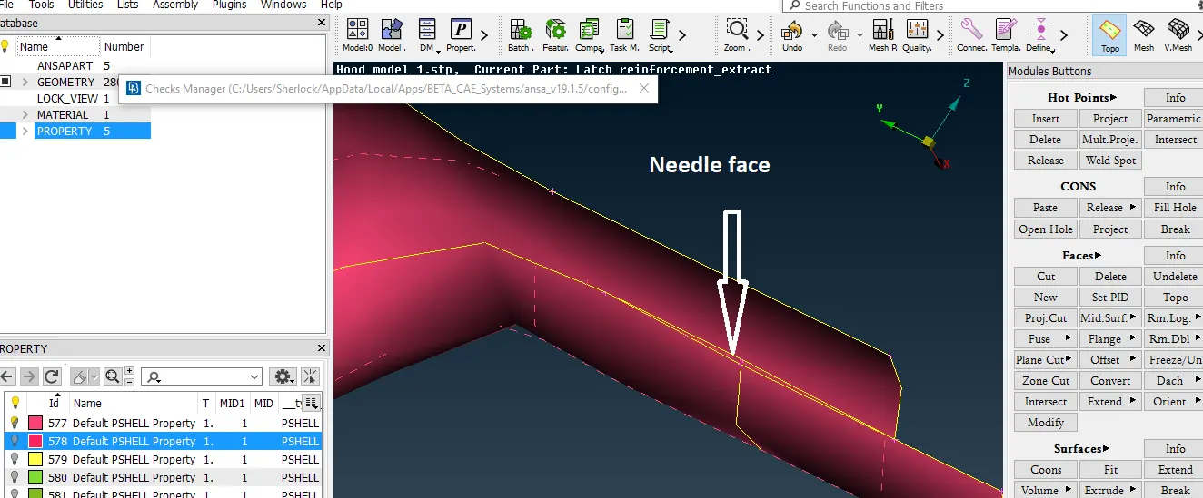
As you can be observed in the above model a relatively very small surface is generated to attached its neighboring surfaces. We can negate these needle faces as they are very small to work.
There are two ways to do that either we can delete the face by going to the topo module (Faces -- Delete ) or right-click on the error showing in the check manager and click on fixing it will automatically fix the error for you by deleting the surface.
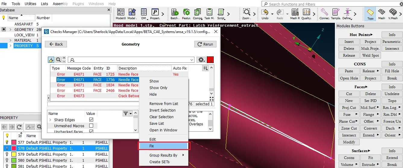
I went with the other manual method to delete these needle faces.
c) Crack between cons:- these errors generally are very small cracks in the geometry. These cracks are very small to identified therefore it's better to go with the auto-fix option. I fix this error with Autofix.
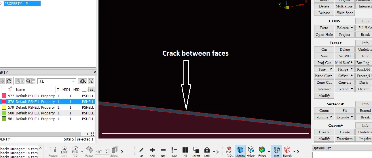
as you can see I had to do a complete zoom-in to see that error only, it's that small.
6)After this, I went for the mid-surfacing which is the most important step that we must follow before meshing. All meshing we are gone do is on the mid surface of the geometry not on an actual model.
7)We can do the mid surface by two methods one is Auto mid surfacing and another one is Manual mid surfacing(Offset) method.
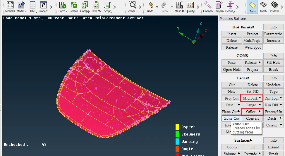
the problem with Auto mid surfacing is that it deletes the main geometry without asking for permission whereas in manual (offset) one it will ask us for permission to delete the geometry or not.
For this model, I went with the manual offset option.
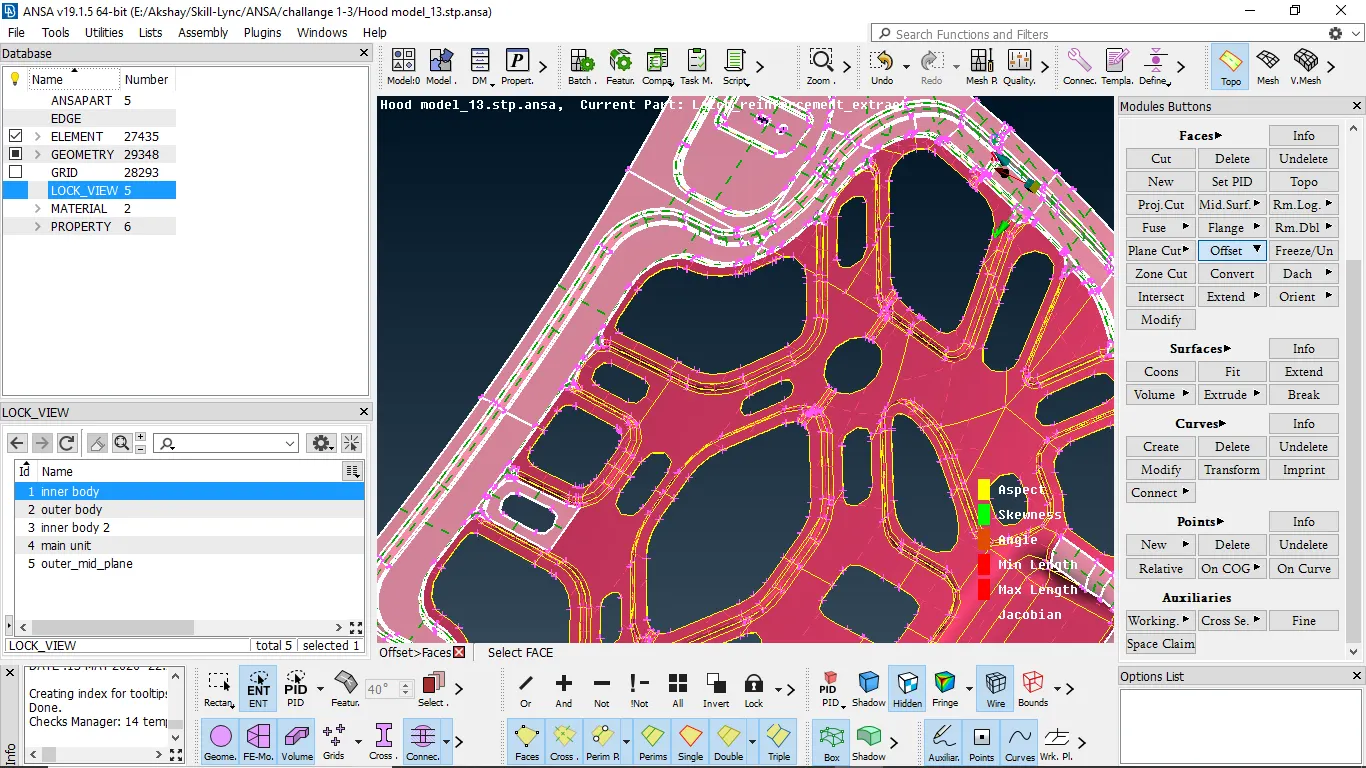
here in the above image, you can clearly see that the hood is symmetric in nature that's why I preferred to take half of it for meshing and then mirror it to its symmetrical plane,
8)After creating a mid surface for each part in the moel save each part / same thickness part in lock view. this how I create three more lock views with three separate elements mid surface in it.
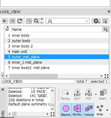
in this model two main inner and outer bodies are of 0.75mm thickness and latches like other support elements are of 1.2 mm in thickness.
So I set the PID (property ID) for each 0.75 mm sheet separately and include all elements with 1.2 mm thickness in one common PID
9) After clearing all geometrical errors throughout the geometry and take the mid surface of each I move forward with meshing. The first thing I did is switch to the mesh module from the topo.
In this process, we have to define the quality criteria and mesh properties first. I defined the quality criteria and mesh properties accordingly.
Another thing I did before head to the meshing is to set the length between two nodes by going to Mesh-- Perimeters -- Length --perimeter + macros ---(set to) 5 which is my Target length for the element.
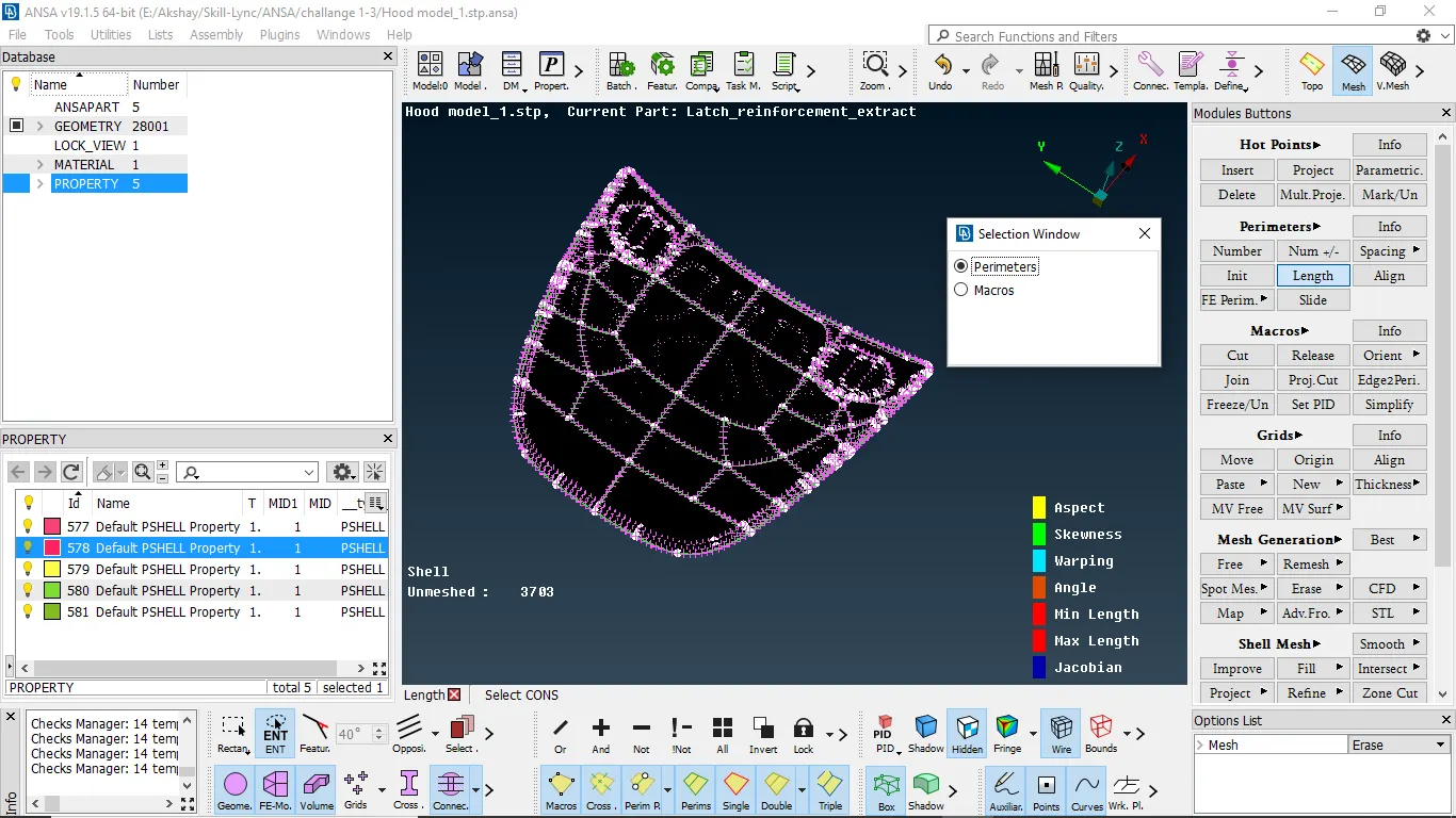
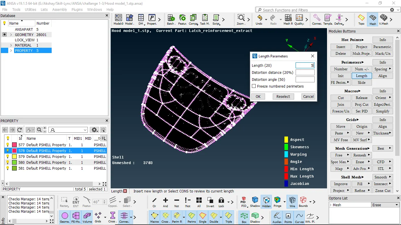
With this, I am sure that each hot point follows my Target length throughout the geometry.
I set it for macros also so I can get evenly spread mesh elements on geometry.
10) I just delete the other half portion of geometry as its symmetrical to the axis and planned to mirror the geometry along with the mesh at the end of meshing to save some time.
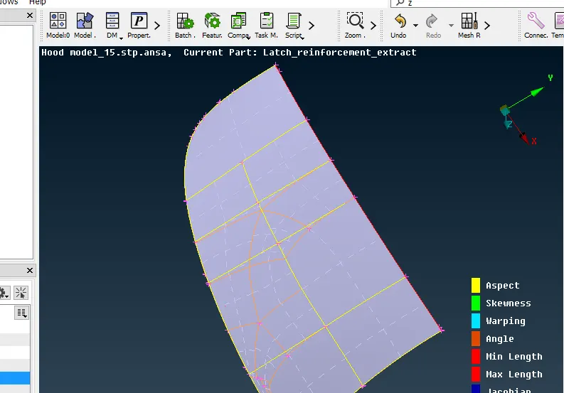
Also here you can see that some lines on the surface of the hood. Some are in orange color and some are in yellow color.
The trick here is the orange lines are the ones deleted and the yellow lines are the new cut lines created by me to make mesh flow more smooth and linear.
11) likewise creating extra cut lines to make stable mesh flow.
A used command like Best, Reconstruct, smooth, Split, swap, num+/-, Init, slide, Mark/Unmark, move, MV point some time Erase to repair and make mesh flow more smoothly.
Errors During Meshing and Solutions.
1) When I went with a regular predefined cut/section I get the mesh-like shown in the below image.
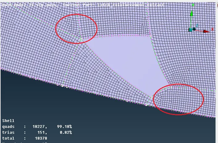
Which is not good if I compared it with an edited version of it like,
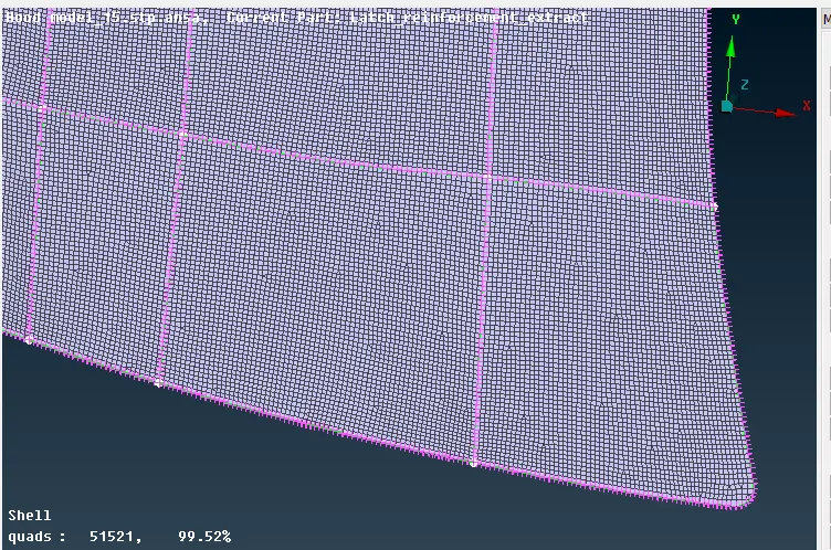
here the mesh is smoother than the previous one. So the important thing to understand is we can modify the construction lines if they are not related to any feature to get better mesh flow.
2)In some cases near the feature, there are extra construction lines to defined the feature. that may cause fail the element/feature for the Quality criteria we set. That's what happens during this model mesh.
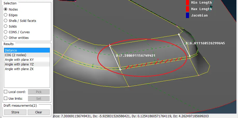
As in our Quality criteria, we defined the Target length of 5 mm along with Min to Max limit 3 to 7mm respectively.
The hatch surface had a length of 0.488 which is much lesser than our defined length with including its limit, so I just measure the adjacent line length to eliminate one line from the hatch surface. This way I won't have to compromise with the feature shape.
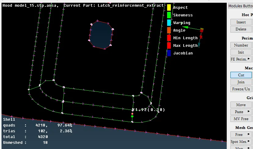
After eliminating the middle line I get the result as shown in the above image. means I able to capture the feature anyway by defeaturing.
3) sometimes I had to create new cut lines on geometry to avoid quality failure.
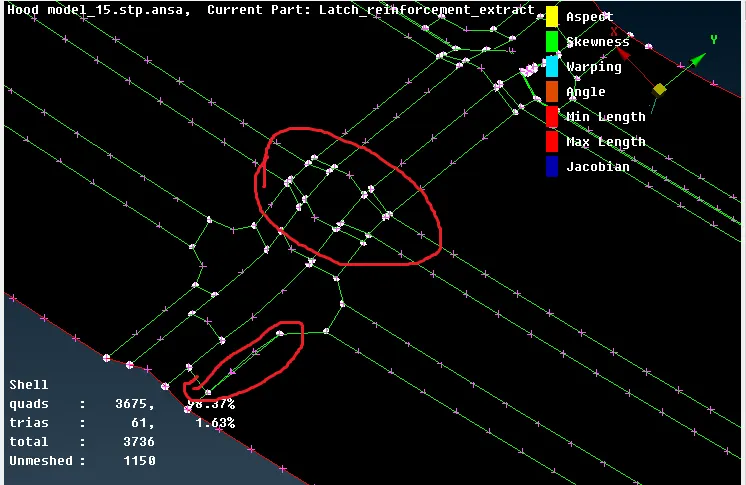
as you can see that these extra close geometrical lines results to fail quality in marked areas to avoid this I arrange that,
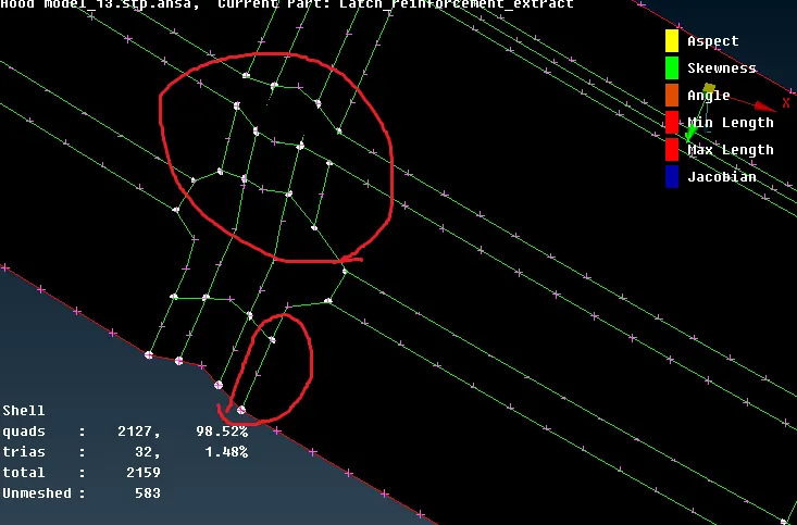
Here I Perform defeaturing to avoid quality failure, you can easily identify the difference by comparing the image.
here are some examples of defeaturing
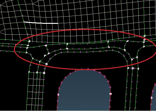
Here the best option for catch the feature geometry is used Datch option from topo module which will create a centerline along with the feature.
4) During the meshing, I faced some quality issues one of them is due to Hem bend at the end of the Outer extract along the edge.
This Hem bend is failing for minimum length issue as well as the Aspect ratio.
In which we can compromise over its minimum length issue by instructor advise. But for clearing the Aspect error I had to move the point until I get a satisfactory result.
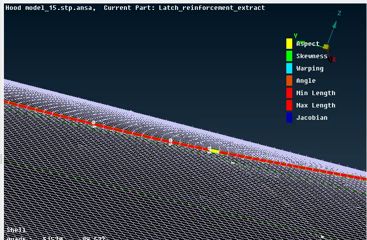
to move this point I used the move option from the mesh module (Mesh--Grids--Move)
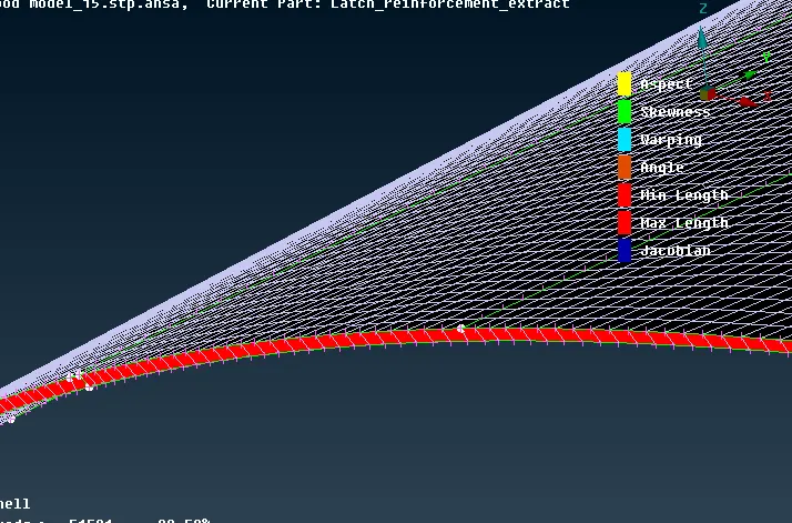
5) Another example is the blow image where elements are failing for in length and Jacobian.
At this point, I did meshing over the maximum surface and don't want to disturb the other side mesh because only of this element failure.
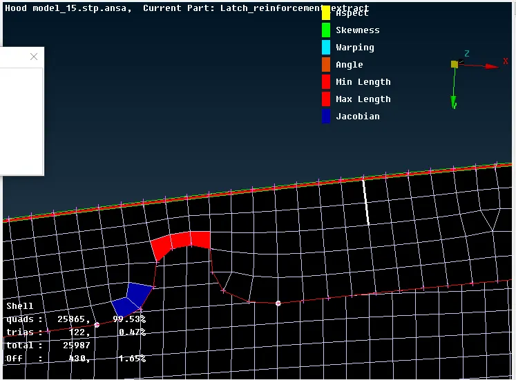
so first I create the border by using the Edge ti Perimeter option then go for Reconstruct and Smooth to eliminate the error.
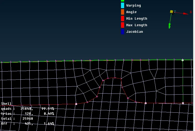
Most of the time these sorts of failures can be eliminated by Reconstruct and smooth option.
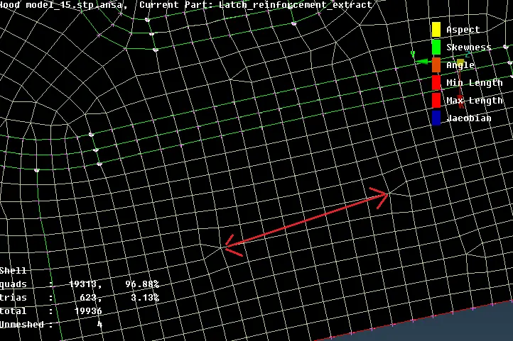
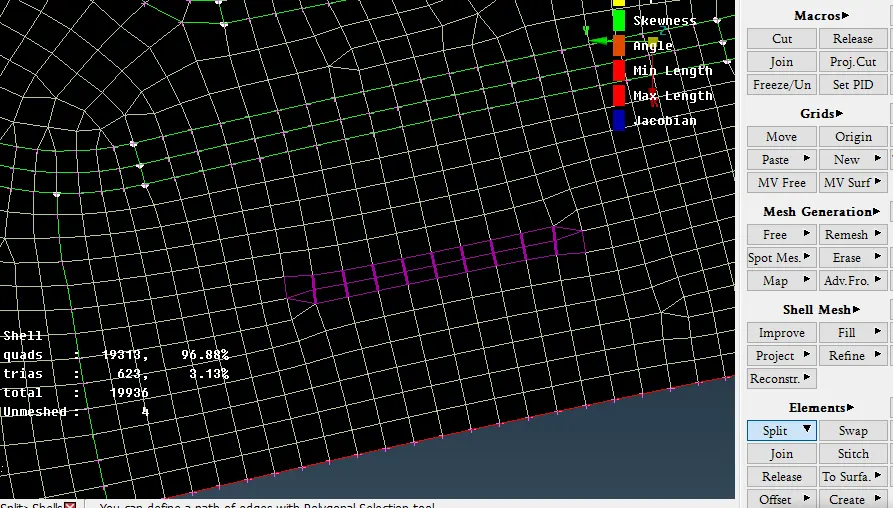
6)There shouldn't any triple con facing to each other we can eliminate this by merging to one another by split option.
Basic Rules during pre-processing of Sheet metal model
1) Perform a Topology operation on the body as soon as you import it. that will eliminate most of the distorted parts and errors.
2) Go for Geometric clean-up. Eliminate all Geometrical error occurs in the model due to importing (Platform changing).
3) Separate out the different thickness models, save in different lock views, Which will help you to understand the model, and it's easy to handle part one by one in the case of Assembly.
4) After that go for mid-surfacing which is the most important step in Meshing because you have to perform meshing on the mid surface, not on actual geometry. So it's more important to take the mid surface of every small feature in it along with the main geometry.
5) After Mid surfacing, you have to perform topo again to stitch the feature to their adjacent plane. Also, we have to perform Geometry clean-up in case any distortion is there. After that Defeturing is coming where you have to compromise on some feature so that mesh flows mustn't disturb.
6) After that, we can go with the mesh module and start the mesh on the model mid-surface. During meshing its suggest that your elements should be of uniform size. No two trips should be opposite to each other. Your mesh should fall under Quality Criteria You defined. No Quads, Minimum trips.
7) And last, apply thickness to the mesh part by checking the Draw shell as a solid option.
Conclusion
- To perform any kind of analysis meshing is important as it helps to spread out the flow of stress evenly through the body.
- Smoother the mesh better the Force distribution during analysis.
- We can't perform Analysis on the actual 3d model either it is solid sheet metal or plastic, we have to convert the model along with its feature into the solver and post-processing software adaptable format and Ansa(pre-processing) is one of the platforms for it.
- Only the Mesh is passed for the analysis, not the actual geometry nor the mid-plane.
- To get better mesh around the feature dividing it into a number of parts is one of the best options.