vehicle dynamics project 1
Introduction:
Objective:
In this project a first order selection of spring,antirollbar,and Instantaneous centers for the suspension links is performed
Excel sheet calculation flow:Note:Detailed equations are in the excel sheet
Ride frequency
1-inputs are declared, with an assumed front and rear spring rate
2-target rear frequency calculated using time lag
3-corner unsprung weights are calculated
4-axle weight calculated
5-corner sprung weight calculated
6-wheel rate calculated
7-sprung ride rate calculated
8-actual natural frequency calculated, this is done for front and rear
9-unsprung ride rate calculated
10 unsprung natural frequency calculated
11- the front spring rate is iterated until the target front frequency is reached
12-the rear spring rate is iterated until the target rear frequency is reached (with in 5% deviation) while making sure that the spring rates can be increased only in 0.25 ib/inch increments
Anti roll bar:
using the spring values obtained in the frequency as a baseline input:
1-distance cg from front axle calculated
2-distance x and h_arm is calculated which is the distance between center of gravity and roll axis
3-front and rear axle sprung weights are calculated
4-front and rear axle unsprung weights calculated
5-then unsprung mass front and rear load transfer is calculated using unsprung weight c.g at wheel center
6-then direct lateral load transfer is calculated front and rear(kinematic) using front and rear roll centers
7-then total vehicle lateral load transfer is calculated using center of gravity height from the ground
8-then front load transfer is calculated based on the static weight percentage on this axle
9-then inorder to give the vehicle safer understeer characteristics a 5% more weight transfer is added to the front
10-then the rear load transfer and adjusted rear load transfer is calculated(5% less)
12-then front and rear roll load transfer is calculated(elastic) by subtracting the direct load transfer and unsprung load transfer from the total lateral load transfer
13- then total roll stiffness is calculated from the roll gradient equation(elastic) using h_arm which is distance betwen c.g. and roll axis
14-then from the roll load transfer equation ,the front axle stiffness can be calculated (using h_arm)
15-then rear roll stiffness is calculated from the total roll stiffness
16-then tyre contribution front and rear is calculated
17-then it is subtracted from the front and rear roll stiffness to get the required stiffness at wheel center level for front and rear
18-then wheel rate contribution to wheel center stiffness is calculated
19-then anti roll bar contribution is the difference between the required stiffness at wheel center level and the wheel rate (springs contribution)
20-then auxiliary stiffness is calculated, and we make sure it is within the required constraint level, otherwise the spring values should be changed
20- then anti roll bar diameters are calculated
21-then it is approximated to the nearest 0.25 inch
22-this will require redoing the calculations to make sure that the roll gradient in the target levels
23- then a new roll bar stiffness is calculated
24-then added to the wheel contribution to get new wheel center stiffness
25-then tyre contribution is added
26-then total roll stiffness is computed
27-then new roll gradient is calculated, if it is not is the required target deviations, change the anti-roll bar diameters in 0.25-inch increments
Acceleration pitch (assumed 1 g acc.):
using ride frequency springs as base line inputs:
1-without compensations calculations are performed
2-total longitudinal load transfer calculated
3-static axle load is calculated
4- dynamic axle load is calculated
5-front and rear wheel rate calculated
6-front and rear wheel rate calculated
7-front and rear end deflection calculated
8-pitch angle calculated
9-pitch gradient calculated
10-instant center location assumed with the horizontal distance set in the advised range(70-120 inch)
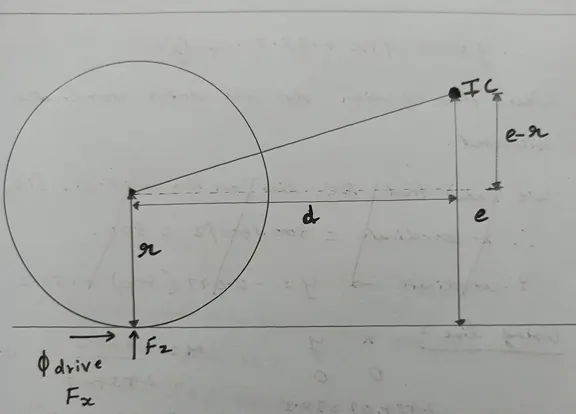
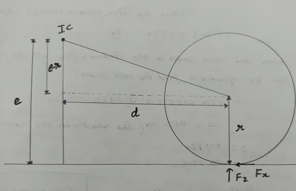
11-front anti lift rear anti squat angles calculated (tyre radius should be subtracted because suspension links are not loaded in an independent suspension in acceleration)
12-then angles calculated for 100% anti lift and for 100% anti squat
13-then from it anti squat and lift percentage is calculated
14-then new front and rear end deflection is calculated after compensation
15-then a new pitch angle and pitch gradient is calculated
16-check the new pitch gradient is within the required range, otherwise change the vertical position of the ic center as it is more effective than horizontal, also make sure no anti characteristic exceed 100%
Braking pitch:
(assumed 1 g dec.):
using ride frequency springs as base line inputs:
1-without compensations calculations are performed
2-total longitudinal load transfer calculated
3-static axle load is calculated
4- dynamic axle load is calculated
5-front and rear wheel rate calculated
6-front and rear wheel rate calculated
7-front and rear end deflection calculated
8-pitch angle calculated
9-pitch gradient calculated
10-the instant center locations are made the same as the acceleration gradient
11-front anti-dive rear anti lift angles calculated (tyre radius shouldn't be subtracted because suspension links are loaded in any suspension in braking)
12-then angles calculated for 100% anti dive and for 100% anti lift
13-then from it anti dive and anti-lift percentage is calculated
14-then new front and rear end deflection is calculated after compensation
15-then a new pitch angle and pitch gradient is calculated
16-check the new pitch gradient is within the required range, otherwise change the vertical position of the ic center as it is more effective than horizontal, also make sure no anti characteristic exceed 100%
17-Any change to the ic values should then be applied to the acceleration gradient and then we need to check its gradient to be with acceleration gradient target levels and this should go back and forth, and from many iterations, a single specified set of instant center locations should satisfy both the braking gradient and the acceleration gradient
Matlab code:
clear all
close all
clc


total_weight=3500*0.45359237
front_axle_unsprung_weight=200*0.45359237
rear_axle_unsprung_weight=240*0.45359237
wheel_base=0.0254*98
front_spring_rate=198.75*175.126790921
rear_spring_rate=245*175.126790921
front_ratio=0.55
front_tire_rate=175.126835*1567
rear_tire_rate=175.126835*1764
target_front_freq=1.35
motion_ratio_front_design=0.95
motion_ratio_rear_design=0.8
velocity= 0.44704*65
target_front_freq=1.35
timelag=(wheel_base)/(velocity)
target_rear_freq=1/((1/target_front_freq)-timelag)

corner_weight_unsprung_front= front_axle_unsprung_weight/2
corner_weight_unsprung_rear= rear_axle_unsprung_weight/2
rear_ratio=1-front_ratio
axle_front=total_weight*front_ratio
axle_rear=total_weight*rear_ratio
corner_front_sprung=(axle_front/2)-corner_weight_unsprung_front
corner_rear_sprung=(axle_rear/2)-corner_weight_unsprung_rear
wheel_rate_rear=(rear_spring_rate)*((motion_ratio_rear_design)^2)
ride_rate_rear=(wheel_rate_rear*rear_tire_rate)/(wheel_rate_rear+rear_tire_rate)
actual_nat_freq_rear=(1/(2*pi))*(sqrt((ride_rate_rear)/(corner_rear_sprung)))
wheel_rate_front=(front_spring_rate)*((motion_ratio_front_design)^2)
ride_rate_front=(wheel_rate_front*front_tire_rate)/(wheel_rate_front+front_tire_rate)
actual_nat_freq_front=(1/(2*pi))*(sqrt((ride_rate_front)/(corner_front_sprung)))


%unsprung weight design

ride_rate_front_unsprung=(wheel_rate_front+front_tire_rate)
nat_freq_front_unsprung_design=(1/(2*pi))*(sqrt((ride_rate_front_unsprung)/(corner_weight_unsprung_front)))
ride_rate_rear_unsprung=(wheel_rate_rear+rear_tire_rate)
nat_freq_rear_unsprung_design=(1/(2*pi))*(sqrt((ride_rate_rear_unsprung)/(corner_weight_unsprung_rear)))


time=linspace(0,3,300)

for i=1:length(time)
    t=time(i)
   front_damped_freq_design(i)=exp(t)*sin(2*pi*actual_nat_freq_front*t)
    rear_damped_freq_design(i)=exp(t)*sin(2*pi*actual_nat_freq_rear*(t-timelag))
    i=i+1
end

plot(time,front_damped_freq_design);
hold on
plot(time,rear_damped_freq_design);
title('flat ride plot');
xlabel('Time(s)');
ylabel('Amplitude');
legend('Front','Rear');
grid on
code steps:
Note detailed calculations and equations are in the excel sheet:
1-inputs are declared
2-target rear frequency calculated
Timelag=wheelbase/velocity
target rear fequency=1/(1/target front fequency)-time lag
3-corner unsprung weights are calculated
=axle unsprung weight/2
4-axle weight calculated
=totalweight*f/r ratio
5-corner sprung weight calculated
=axle weight-unsprung corner weight
6-wheel rate calculated
=spring rate*(mr)^2
7-sprung ride rate calculated
=(wheelrate*tyre rate)/(wheel rate +tyre rate)
8-actual natural frequency calculated,this is done for front and rear
=(1/(2*pi))*sqrt(ride rate/corner sprung weight)
9-unsprung ride rate calculated
=wheel rate+tyre rate
10 unsprung natural frequency calculated
=(1/(2*pi))*(sqrt((ride rate front unsprung)/(corner unsprung weight))
11-then exponential damped frequency is plotted
front:exp(t)*sin(2*pi*actual natural frequency*time)
rear:exp(t)*sin(2*pi*actual_nat_freq_front*(t-time lag))
-This is done by using linspace commands which set the x limits between 0 and 3 second and it will calculate the output 300 times in between
-Then for loop is used with a counter having the same value as the number of elements in the linspace array
-It will then pick an element form the array and with the same order as the counter and make it the time which will calculate the output based on it
-Then it will calculate the damped front and rear frequencies and then the counter is increased by one and so on
-Then output is plotted,a hold on command is used to plot the two curves on a single graph
-Then it is titled and the axis are titled and a legends are put on the plot ,and grid on command is used to show the grid
output values:
|
Target required |
Target achieved |
|
|
Front ride frequency (hz) |
1.35 |
1.35 |
|
Roll gradient(deg/g) |
3.8 |
3.72 |
|
Acceleraton pitch gradient (deg/g) |
2 |
2.049 |
|
Braking pitch gradient (deg/g) |
1 |
0.965 |
|
constraints |
Achieved |
|
|
Maximum auxiliary front roll stiffness % |
60 |
52 |
|
Maximum auxillary rear roll stiffness% |
30 |
28.5 |
front frequency:1.35 Hz
rear frequency:1.45 hz (target 1.52 Hz)
front spring:198.75 ib/inch
rear spring:245 ib/inch
front anti rollbar diameter:0.75 inch
rear anti roll bar diameter:0.5 inch
auxillary roll stiffness % front:52%
auxillary roll stiffness % rear:28.5%
roll gradient:3.72 deg/g
Anti charachteristics:
acceleraltion:
front anti lift%:17.5%
rear anti squat%:7.5%
acceleration pitch gradiant:2.049 deg/g
braking:
front anti dive%:71.19%
rear anti lift%:47.46
braking pitch gradiant:0.965 deg/g
Instant center locations:
Front IC vertical distance from CP=15.5 inch
Front IC horizontal distance from CP =75 inch
Rear IC vertical distance from CP=15.5inch
Rear IC horizontal distance from CP=75inch
Note:all outputs are within ±5% from the specified targets
flat ride plot:
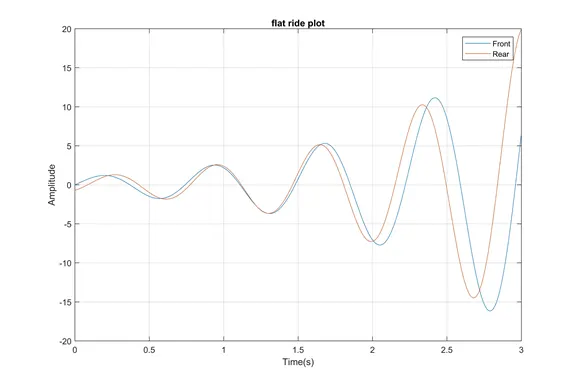
at 1 second there will be no pitching because of the frequency matching that has been achieved by making the rear springs stiffer
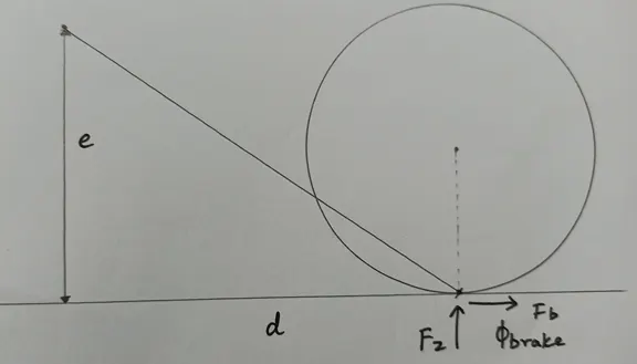
Diagrams:
acceleration:
front anti lift
rear anti squat:
braking:
front anti dive:
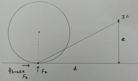
rear anti lift:
Files:
excel sheet file:
https://drive.google.com/file/d/1XBXYmgBFXm46zsw-PwqyUzWnN6mBWFhY/view?usp=sharing
matlab file:
https://drive.google.com/file/d/1OR6ZRRn8XG3DEaAwQUUV-AXs9qxKQMDX/view?usp=sharing