Using the STM32-IDE Nucleo-F401RE Board have to Blink of LED and Interrupt the LED Blinking delay by pressing the Push-Button.
AIM: In this Project I have implemented the code for the STM32-IDE Nucleo-F401RE Board to Blink of LED and Interrupt the LED Blinking delay by pressing the Push-Button.
STM32F401RE MCU BOARD FEATURES:
- Common Features:
- STM32 microcontroller in LQFP64 or LQFP48 package.
- 1 user LED shared with ARDUINO®.
- 1 user and 1 reset push-buttons.
- 768 kHz crystal oscillator.
- Board Connectors:
- ARDUINO®Uno V3 expansion connector.
- ST morpho extension pin headers for full access to all STM32 I/Os.
- Flexible power-supply options: ST-LINK USB VBUSor external sources.
- On-board ST-LINK debugger/programmer with USB re-enumeration capability: mass storage, Virtual COM port, and debug port.
- Comprehensive free software libraries and examples available with the STM32Cube MCU Package.
- Support of a wide choice of Integrated Development Environments (IDEs) including IAR Embedded Workbench®, MDK-ARM, and STM32CubeIDE.
- Board-Specific Features:
- External SMPS to generate Vcorelogic supply.
- 24 MHz or 48 MHz HSE
- Board Connectors:
- External SMPS experimentation dedicated connector.
- Micro-B or Mini-B USB connector for the ST-LINK.
- MIPI®debug connector.
STM32 HAL LIBRARY:
- In general, device drivers are independent of the underlying operating system and are specific to a given hardware configuration. A hardware abstraction layer (HAL) provides a common interface between drivers and higher-level application code.
- The HAL abstracts away the details of how a specific driver works and provides a uniform API to control such devices. We can use the same APIs to access various device drivers across multiple microcontroller (MCU) based reference boards.
- FreeRTOS common I/Oacts as this hardware abstraction layer. It provides a set of standard APIs for accessing common serial devices on supported reference boards.
- These common APIs communicate and interact with these peripherals and enable wer code to function across platforms. Without common I/O, writing code to work with low level devices is silicon-vendor specific.
- STMCube®is STMicroelectronics’s original initiative to ease and accelerate the development cycle of embedded products. STM32Cube covers the STM32 portfolio of microcontrollers.
- It provides the developer with all the low-level drivers, APIs, and enables to dedicate most of the effort to develop the application layer and any required middleware.
STM32 HAL LIBRARY DRIVERS:
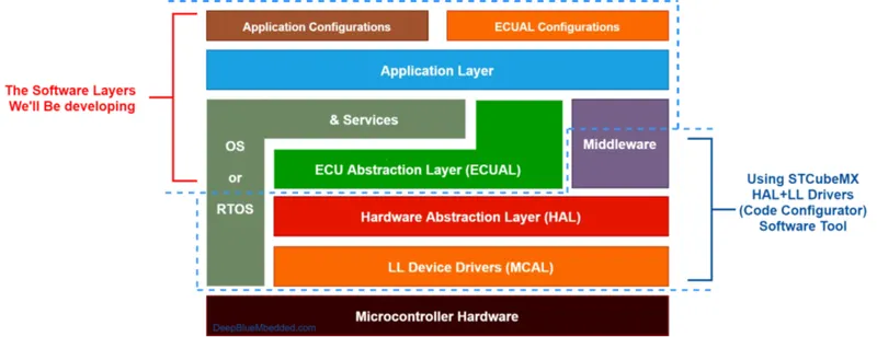
- The STM32CubeMX, a graphical software configuration tool that allows generating C initialization code using graphical wizards.
- The STM32Cube Hardware Abstraction Layer (HAL), an STM32 abstraction layer embedded software ensuring maximized portability across the STM32 microcontroller. The HAL is available for all the hardware peripherals.
- The low-layer APIs (LL) offering a fast light-weight expert-oriented layer that is closer to the hardware than the HAL. The LL APIs are available only for a set of peripherals.
- The HAL and LL are complementary and cover a wide range of applications requirements:
- The HAL offers high-level and feature-oriented APIs, with a high-portability level. They hide the MCU and peripheral complexity to end-user.
- The LL offers low-level APIs at registers level, with better optimization but less portability. They require deep knowledge of the MCU and peripherals specifications.
- The source code of HAL and LL drivers is developed in Strict ANSI-C which makes it independent from the development tools. It is fully documented and is MISRA-C 2004 compliant.
STM32 HAL DRIVERS EXAMPLE:
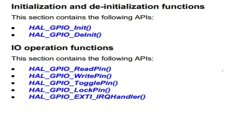
HAL GPIO APIs:
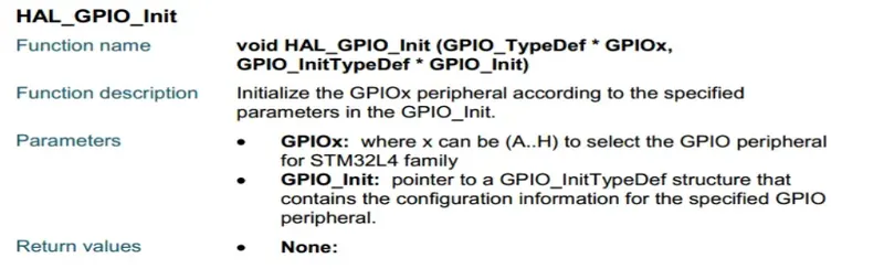
HAL Detailed Function Description:
-
- In the same manner, there are low-level hardware drivers for almost all the hardware peripherals in the STM32 microcontrollers. Including Timers, ADC, USART, I2C, USB, DAC, Comparators, etc.
- We’ll configure these peripherals and generate the initialization C-Code using the Cube MX software tool.
STM32 HAL Concluding Remarks:
- Using the STM32 HAL device drivers can be advantageous in so many situations, and help shorten the development time.
- Especially for projects that fall in the category of “proof of concept”, no one wants to spend so much time building a complete software stack for a specific target then it proves the main idea needs more refinement or the target itself does not perform well enough.
- However, the moderately high-level APIs provided by the HAL may have extra more features than what we may actually need in some situations. So, we end up using more memory space and executing some tasks a little bit slower due to the overhead of the functionalities embedded in the libraries.
- We can use the LL drivers and optimize more at the register level in order to enhance memory utilization or the speed of execution. However, the application at the end would not be easily portable across multiple targets.
- All in all, we’ll be using the STM32 CubeMX tool to generate HAL + LL drivers C-Code to initialize our hardware. Then we’ll be developing the application layer and some middleware stuff on the way.
Processor I Implemented in the Project Before Code Generated:
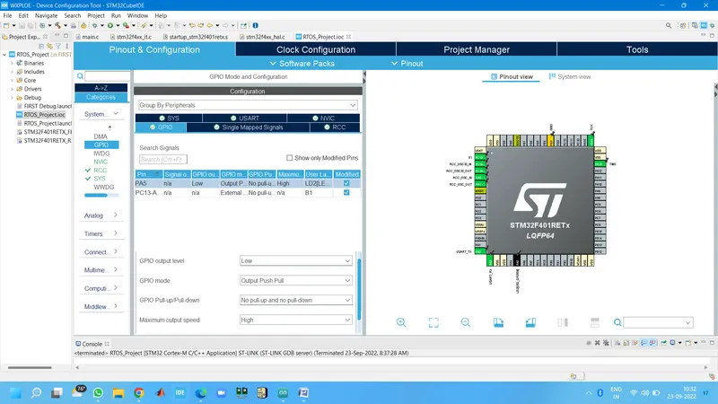
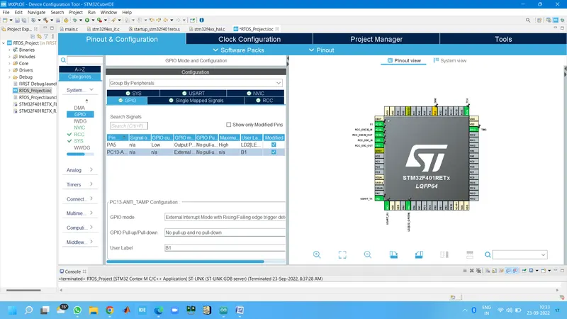
- I have Initialized the GPIO Modes PA5(LED) as the output which is inbuild in the board and B1(Push-Button) as the External Interrupt to implement the delay to Blink LED.
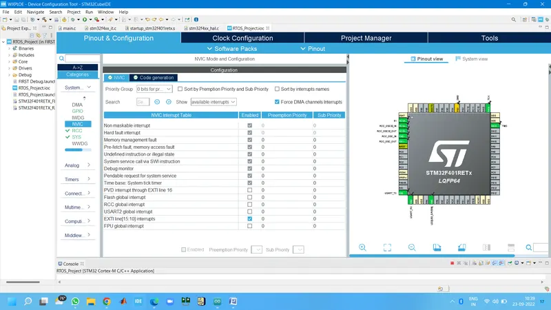
- In NVIC interrupt Table i enable the EXT line[15:10] interrupts
Why I enabled the EXTI line?
- Each STM32F4 device has 23 external interrupt or event sources. They are split into 2 sections. First interrupt section is for external pins (P0 to P15) on each port, and other section is for other events, like RTC interrupt, Ethernet interrupt, USB interrupt and so on.
- GPIO as Interrupt:
- In section one (GPIOs) we have 16 interrupt lines. They are line0 to line15and they also represent pin number. This means, PA0 is connected to Line0 and PA13 is connected to Line13.
- We have to know that PB0is also connected to Line0 and PC0 also and so on. This is for all pins on board, All Px0 (where x is GPIO name) pins are connected to Line0 and let’s say all Px3 are connected to Line3 on the Interrupt channel.
- All pins with same number are connected to line with same number. They are multiplexed to one line.
IMPORTANT: We cannot use two pins on one line simultaneously:
- PA0and PB0 and PC0 and so on, are connected to Line0, so we can use only one pin at one time to handle interrupt from there.
- PA0and PA5 are connected to different lines, they can be used at the same time.
Each line can trigger an interrupt on rising, falling or rising_falling edge on signal.
Ø Interrupt handlers:
- Now, we have selected our pin we want to use. But we have to handle interrupt somehow. This process is described below.
- STM32F4 has 7 interrupt handlers for GPIO pins. They are in table below:
|
Irq |
Handler |
Description |
|
EXTI0_IRQn |
EXTI0_IRQHandler |
Handler for pins connected to line 0 |
|
EXTI1_IRQn |
EXTI1_IRQHandler |
Handler for pins connected to line 1 |
|
EXTI2_IRQn |
EXTI2_IRQHandler |
Handler for pins connected to line 2 |
|
EXTI3_IRQn |
EXTI3_IRQHandler |
Handler for pins connected to line 3 |
|
EXTI4_IRQn |
EXTI4_IRQHandler |
Handler for pins connected to line 4 |
|
EXTI9_5_IRQn |
EXTI9_5_IRQHandler |
Handler for pins connected to line 5 to 9 |
|
EXTI15_10_IRQn |
EXTI15_10_IRQHandler |
Handler for pins connected to line 10 to 15 |
- This table show we which IRQwe have to set for NVIC (first column) and function names to handle our interrupts (second column).
- We have probably also figured, that only lines 0 to 4 have own IRQ handler. Yes, lines 5-9 have the same interrupt handler and this is also for lines 10 to 15. After we set settings for EXTI, we have to add them into NVIC.
Processor I Implemented in the Project After Code Generated:
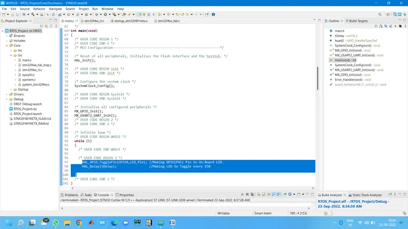
- Implementing code in the main.c file.
- I have initialized the Uint16_t tDelay = 250 Microseconds.
- In while loop I Toggle the GPIOA pin to On-Board LED.
- Next Line given the delay as tDelay.
- Code: while (1) {
/* USER CODE END WHILE */
/* USER CODE BEGIN 3 */
HAL_GPIO_TogglePin(GPIOA,LD2_Pin); //Making GPIO(PA5) Pin to On-Board LED.
HAL_Delay(tDelay); //Making LED to Toggle every 250
}
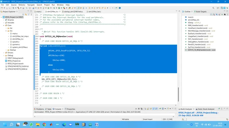
- Implementing code in the stm32f4xx_it.c file.
- In this file I have initialized the code in the external interrupt handler loop.
- In if condition I read the GPIOA port and the pin 5.
- In inner if loop tDelay is equal to 250Microseconds it is going to increase the Led Blinking delay to 1 Sec.
- Else it is going to set the delay to 250Microseconds.
- In this logic when the push button press it should want to increase the delay time, again when i press the Push-Button it should run the previously delay.
- Code: void EXTI15_10_IRQHandler(void){
/* USER CODE BEGIN EXTI15_10_IRQn 0 */
for(int i=0;i<65535;i++){
if(HAL_GPIO_ReadPin(GPIOA, GPIO_PIN_5)){
if(tDelay==250) {
tDelay=1000;}
else{
tDelay=250;}}}
- I am attaching the code Screenshots and the output video of the Project.