Turbo Charger Simulation Project
Objective
To simulate a turbocharger while pressure ratio has 3 different values: 2Bar 2.5Bar and 3Bar. In addition, while simulating one case increase the simulation time to see how it will affect convergence for the angular velocity of the turbine.
Theory
Turbines have been used for centuries to convert mechanical energy into useful mechanical work, usually through a rotating shaft.
In general we face two types of turbines: positive-displacement turbines and dynamic turbines. In our case we simulate a dynamic turbine.
Dynamic turbines are used for flow measuring devices and as a power generators. There are different types of dynamic turbines: Impulse turbines, Reaction turbine, gas and steam turbines and wind turbines.
In our problem we are facing reaction turbine. The reaction turbine itself has some different types, for instance, Kaplan turbine which is axial-flow turbine and Francis turbine which could be radial-flow or mixed-flow turbine.
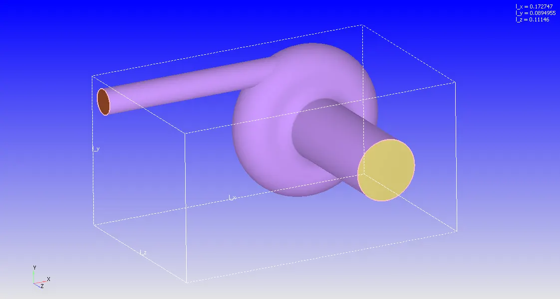
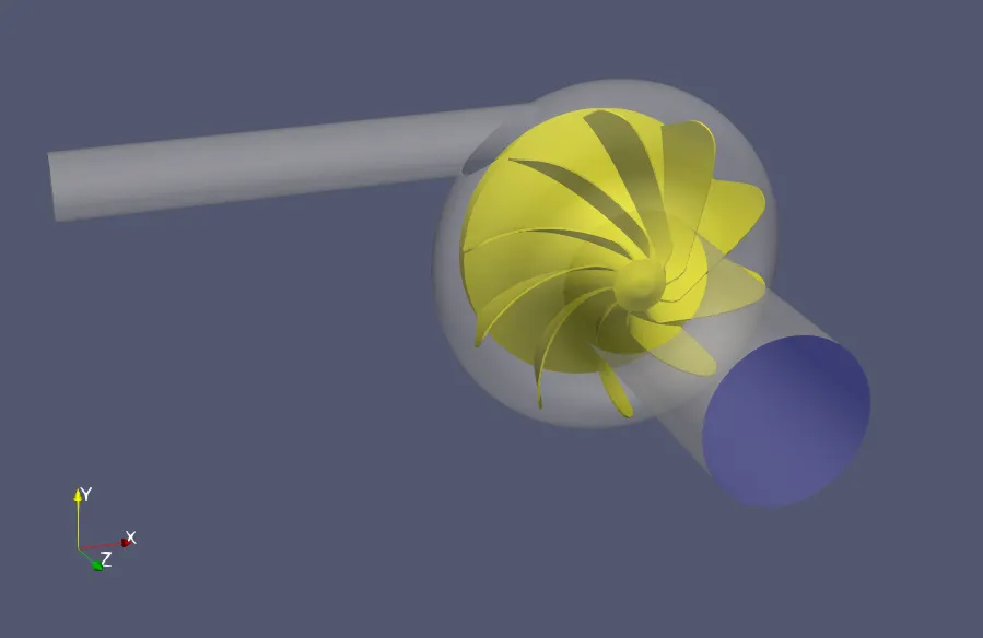
In a Mixed-flow turbine, airflow comes into the turbine system radially and leaves it in an axial direction. In our problem we encounter made-up geometry of a mixed-flow turbine.
- Geometry

Case Setup (2Bar Pressure ratio case)
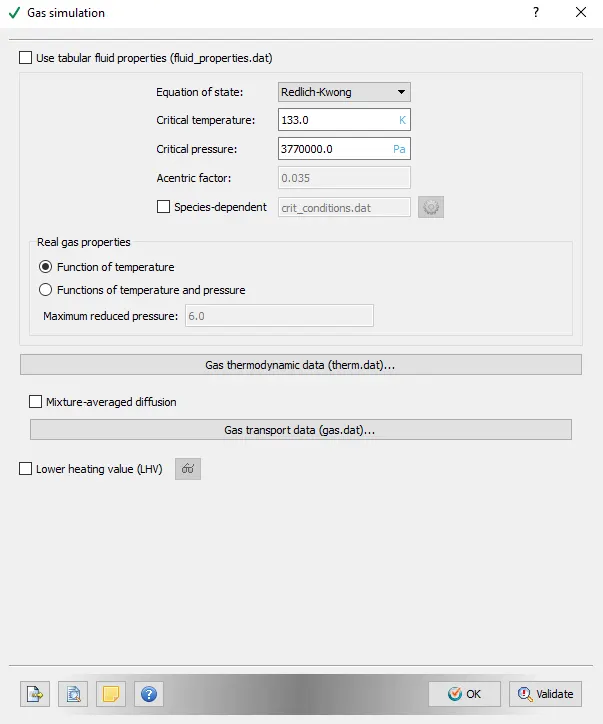
- Gas simulation (Air Real gas)
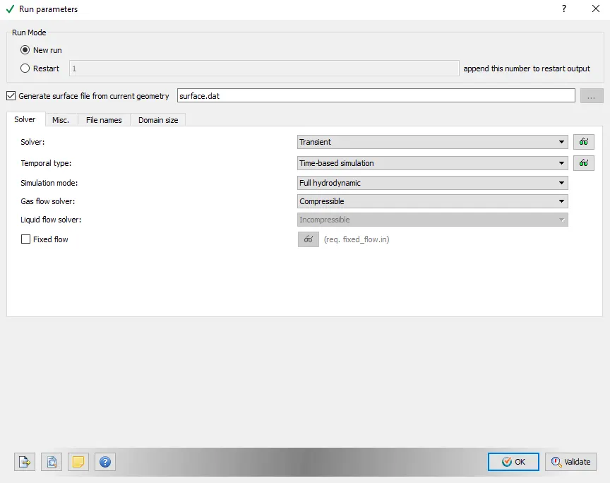
- Run parameters
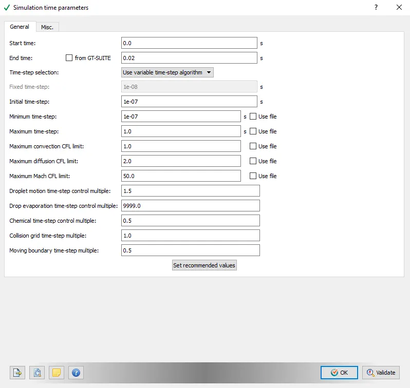
- Simulation time parameters
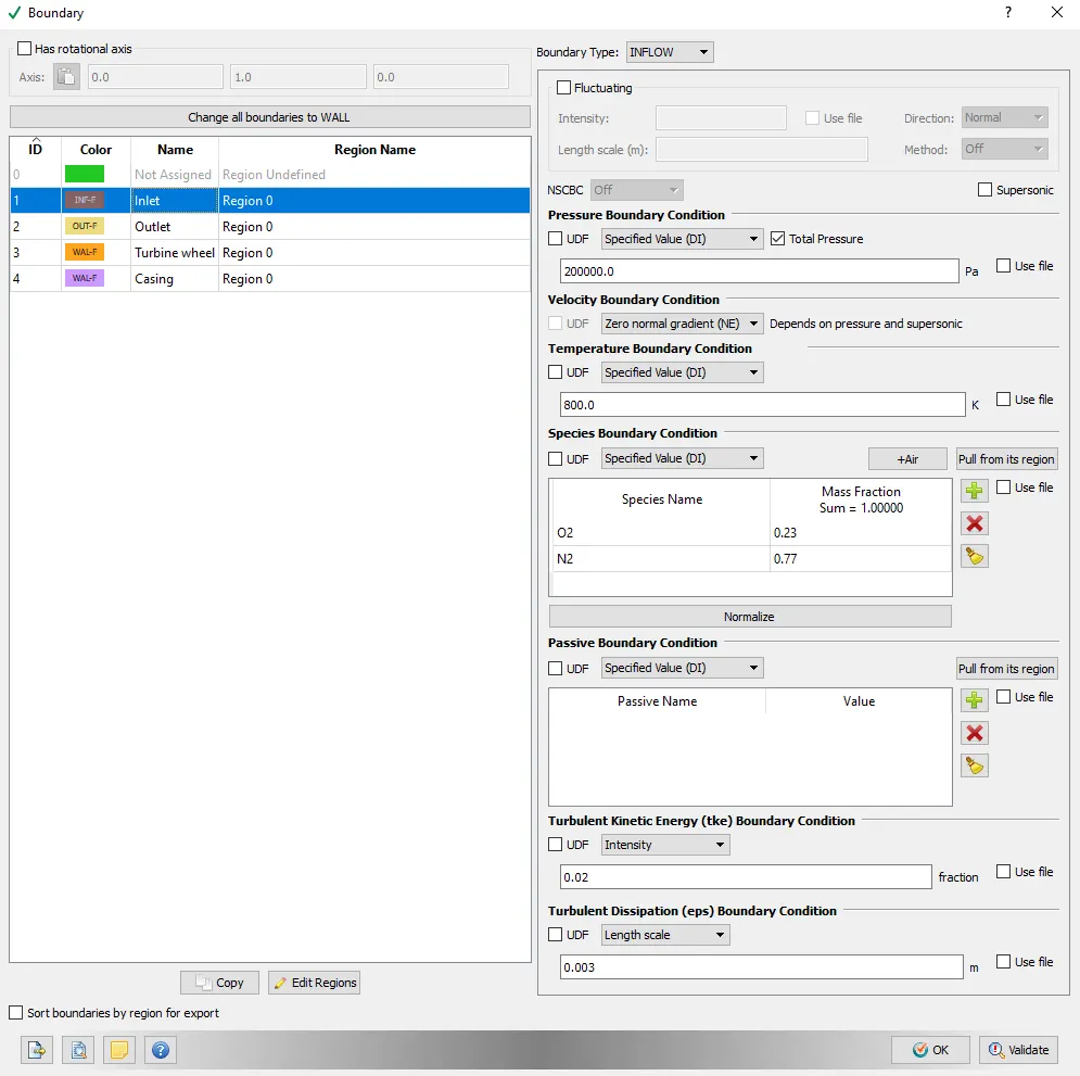
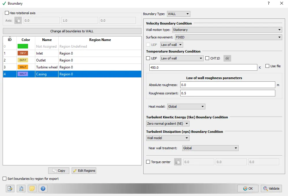
- Boundary conditions
Inlet
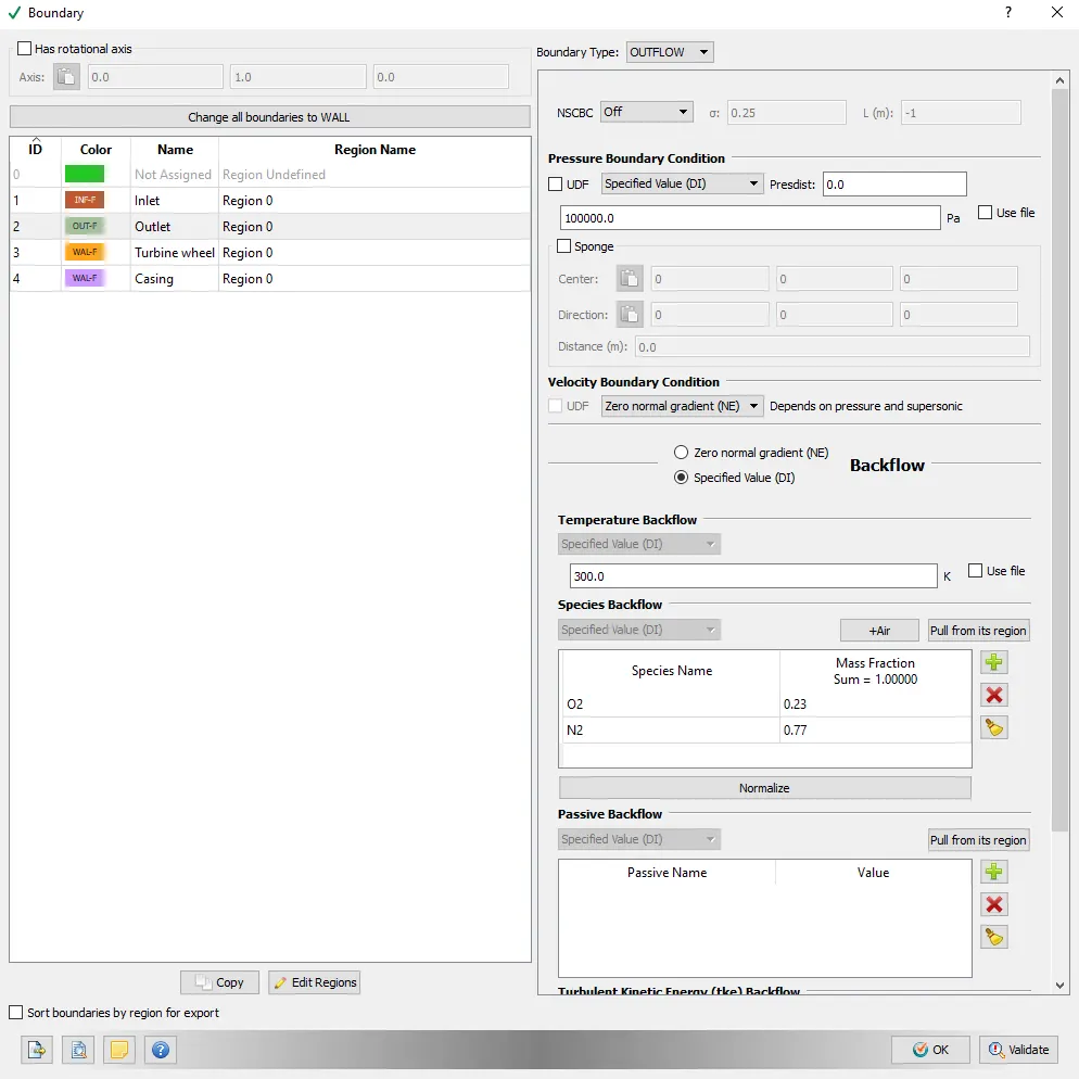
Outlet
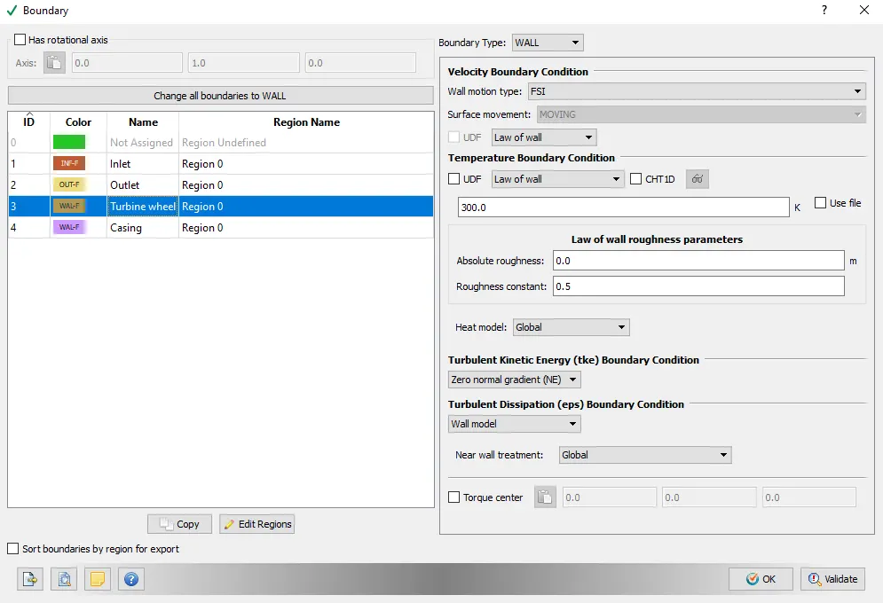
Turbine wheel (Wall)
Casing
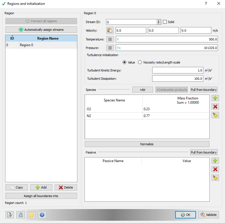
- Regions and initialization
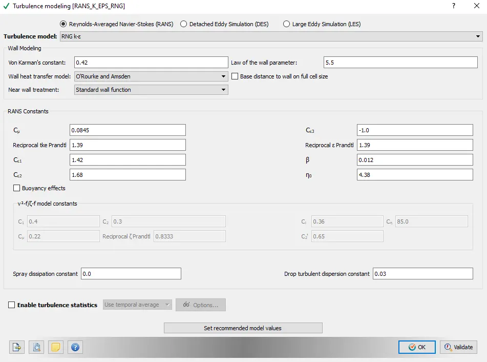
- Turbulence model
- Fluid structure interaction (FSI)
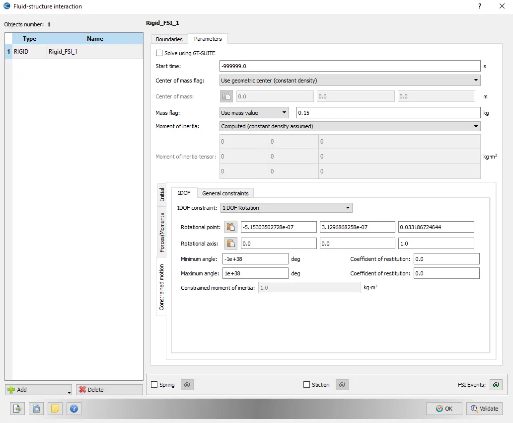
We are using FSI model to determine the degrees of freedom of the turbine wheel and to simulate how the hot inlet air will accelerate the Turbine.
- Base grid
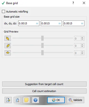
We should include that this simulation is just educational, we dont try to run grid dependence test or approach desired Y+ due to limited computational power.
That's why we have base grid size of 1.5mm which as a whole leads total cell count to be approximately 66K cells.
Post processing
As we already mentioned we run 3 cases with different inlet pressure values: 2Bar, 2.5Bar and 3Bars.
- Rotational velocity (All 3 cases)
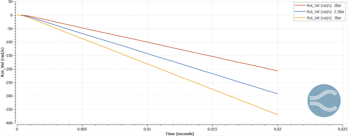
As you see while increasing inlet pressure the turbine wheel tends to generate rotational speed quicker, it's obvious because as we increase pressure we provide more energy to the system which proportionally is converted to mechanical work which forces the turbine wheel to start rotating along it's free degree of freedom which is defined in FSI module in the Figure named "Fluid structure interaction (FSI)".
- Rotational acceleration (All 3 cases)
- Temperature and density comparison at the inlet and the outlet (2Bar case)
Temperature at the Inlet and the Outlet
Density at the Inlet and the Outlet (2Bar case)
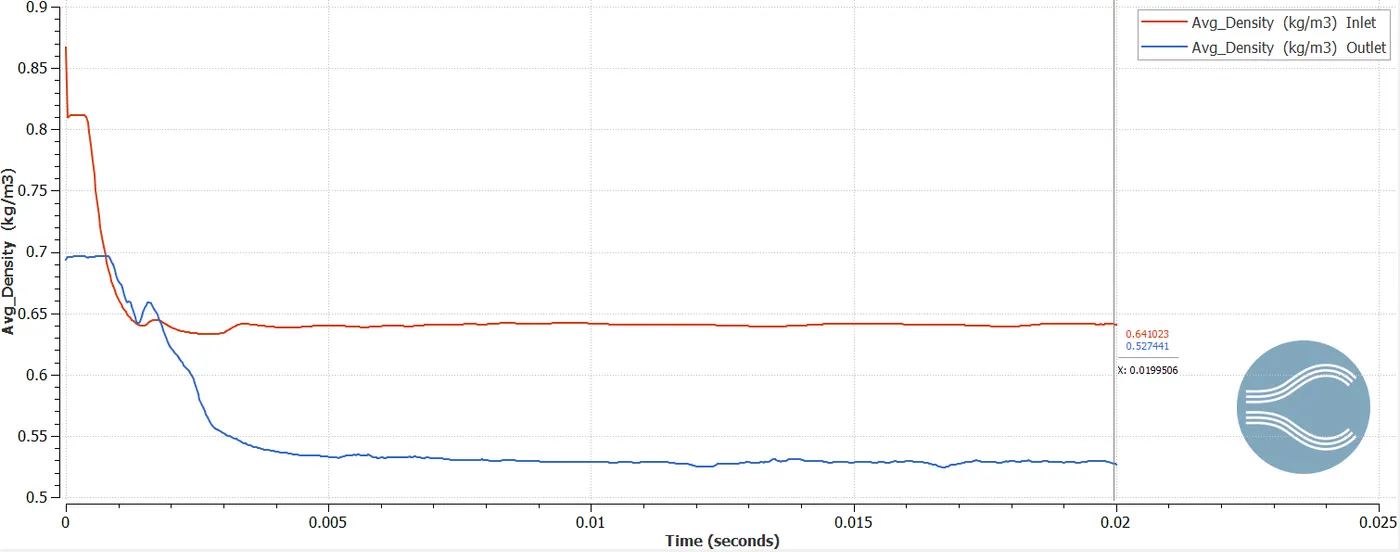
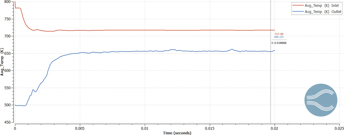
If you take a look at the 2 last figures above, you may be confused to see that while the temperature at the outlet is less than at the inlet how the density of air could be less at the outlet than at the inlet. As we know from the thermodynamic course while temperature decreases density should rise, however we almost forgot to include pressure in our discussion.
According to the ideal gas law: `P = rho*R*T` - Where `P` is pressure, `rho` is density, `R` is gas constant 287J/kg/k for air and `T` which is temperature in Kelvin.
As we see from the equation mentioned above while temperature decreases density should rise if the pressure remains to be the same but as we know we have pressure difference between the inlet and the outlet which drives the air to flow in the direction towards the turbine wheel where pressure discharges and the thermal energy is converted into the mechanical work.
Pressure at the Inlet according to the BC conditions is 2Bars and at the Outlet 1Bar, this difference drives to flow and generates high speed flow in the turbine section.
- velocity differences in all 3 cases.
Velocity at the Inlet and the Outlet (2Bar case)
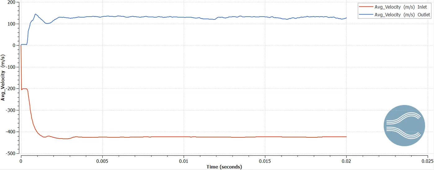
As you see due to pressure difference we encounter high values of velocity at the inlet.
Note: Dont be confused by the negative values, which means that flow goes inside the domain and positive values mean that the flow goes outside the domain.
While increasing the pressure it's intuitive to consider that velocity will increase as well.
Velocity at the Inlet (All 3 case)
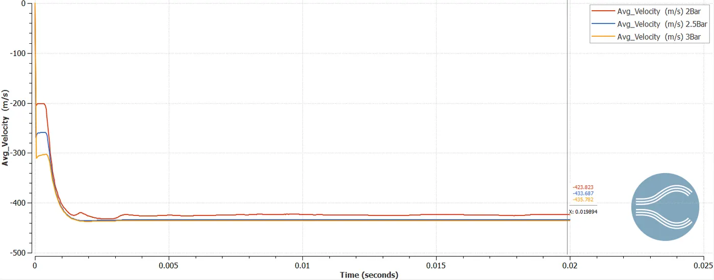
As we see velocity increases, however it's noticable that from pressure 2.5Bar to 3Bar velocity increase is negligible, It's interesting why that happens. Let's have a look at the densities at each pressure case.
Density at the Inlet (All 3 case)
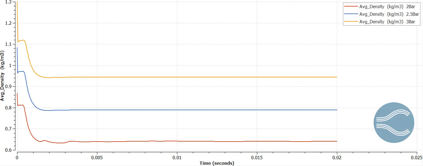
As we increase pressure flow becomes more compressible which encumbers velocity to increase significantly, if we increase the cross section of the inlet like we encounter in De Laval Nozzle velocity should increase significantly.
- Animation (Velocity and Pressure Contours)
Velocity and Pressure contours (2.5Bar case)
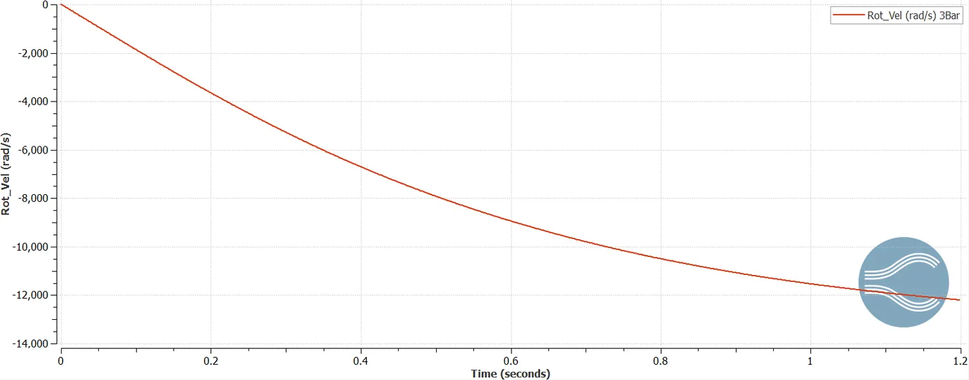
Simulation time was increased up to 1.5seconds to see the rotational velocity convergence.
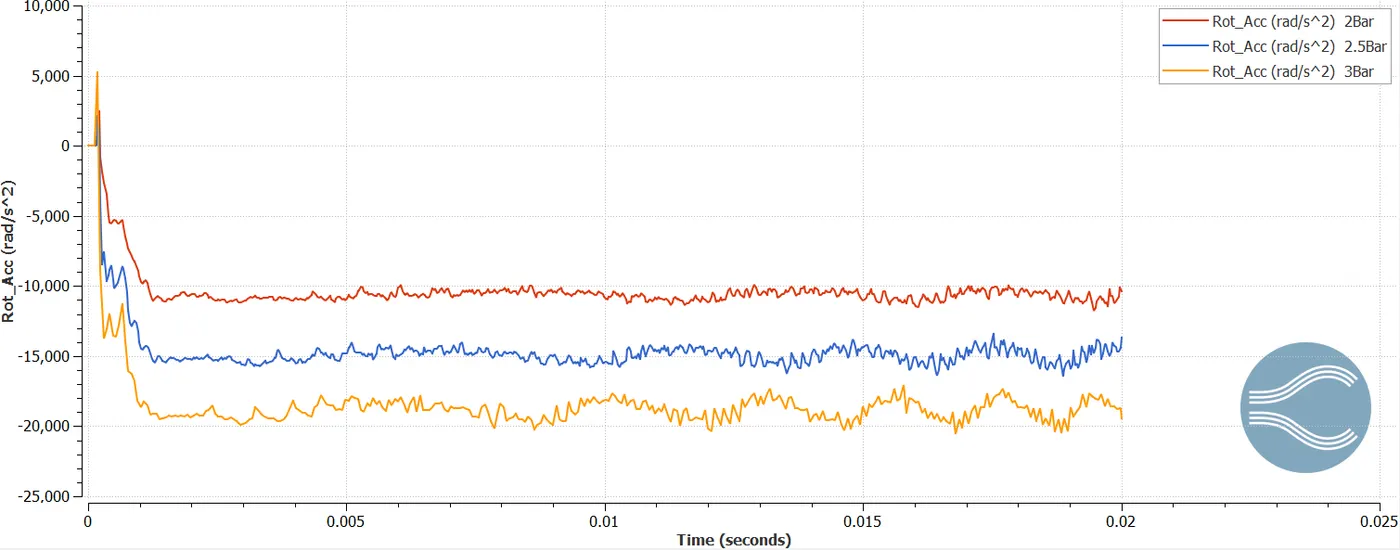
We simulated all 3 cases and understood how the pressure ratio effects the turbine wheel rotational velocity and acceleration, however simulation time which is 0.02 seconds appeared to be less than enough to see the convergence of the rotational velocity, therefore we increased simulation time up to 1.5seconds.
- Rotational velocity (3Bar case. Simulation time 1.5seconds)
- Rotational acceleration (3Bar case. Simulation time 1.5seconds)
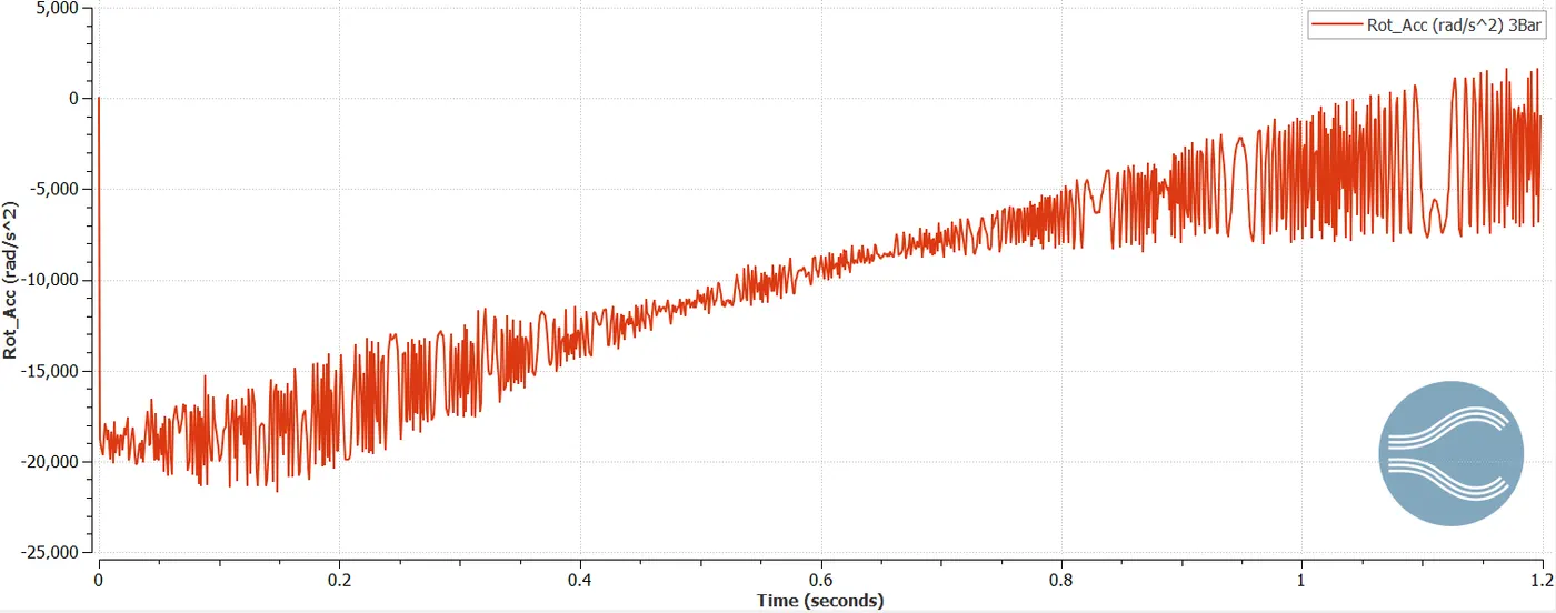
As we see from the 2 last Figures above it's clear that simulation is pretty close to converge, Unfortunately this case took extremely large amount of time (approximately 60 days) that's why we could not wait till the end to see the complete convergence, however from the figures above it's noticable that rotational velocity will become constant approximately at 12000rad/s which is about 120K RPM.
- Animation (Velocity and Pressure Contours)
Velocity and Pressure Contours
Conclusion
We successfully simulated all 3 cases. Understood pressure ratio effect on a rotational velocity. Simulated one case for extended time to see the convergence of the rotational velocity.