3D Meshing of Intake Manifold
Objective: To perform topology cleanup and generate a 3D Volume Tetra mesh for the intake manifold according to the given criteria.
Procedure:
- The model was imported and the topology of the model was cleaned up. Some minor fillets which were less than the minimum length of 1mm were defeatured as they would have led to element failure.
- A 2D shell mesh was generated on the intake manifold which was later converted into a 3D volume mesh.
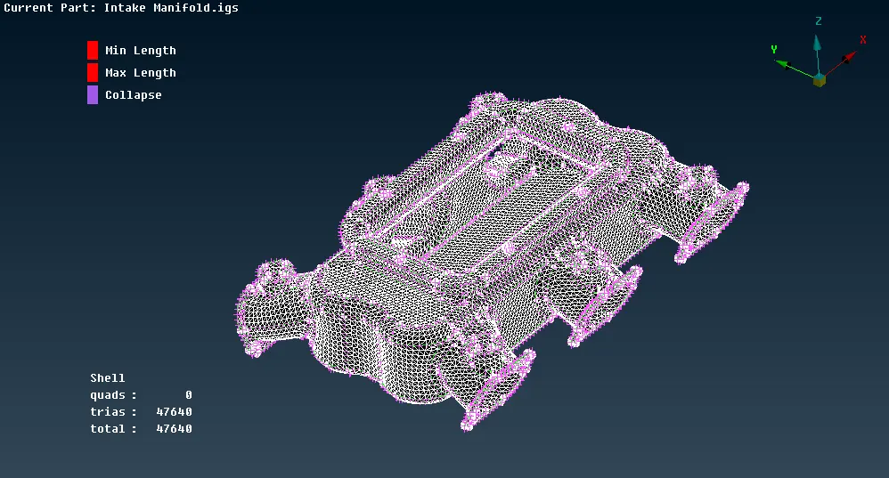
- In critical areas like holes, fillets, and other curved surfaces, a mesh with only orthogonal tria elements was generated while on the flatter surfaces, a normal tria mesh was generated since ortho tria elements require more processing time than the normal tria elements. The finalized shell mesh is as shown below.
- After shell meshing the model, it was defined as a volume from the 'volume mesh' mode, and using the 'tetra rapid' option, a 3D tetra mesh was generated.
- The model was checked for failing elements and the elements failing for a tet collapse of 0.2 were corrected manually using the 'MV Free' option to move the nodes.
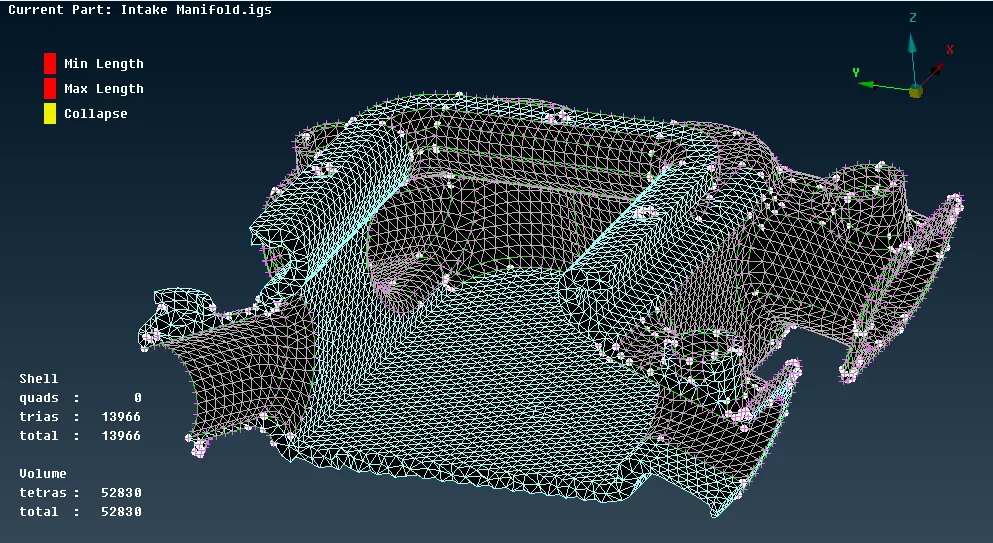
- After ensuring there were no failing elements and the mesh flow was proper, the mesh was finalized as shown below.
The time required: 2 hours
GDrive link for the model: Intake Manifold
"ANSA" "CAE" "FEA"