To study the different types of interfaces and to compare the results of radioss simulation for each interface case
Aim :
1) To study the different types of interfaces and to compare the results of radioss simulation for each interface case.
2) To create mesh with size of 6mm for bumper assembly.
Scope of the project:
1) In this project first we have perform 2d meshing on bumper assembly with the element size of 6mm.
2) For crush tube we have considered six different cases to study different interface types.
3) Type 11 contact is created for crush tube and simulation results are compared with type 7 contact
4) Effect of Inacti is observed by changing its value and performing radioss analysis.
5) Effect of notches on crush tube simulation is observed.
5) For each case different contours and plots are observed to study the interface types.
Introduction :
- What is Hypercrash?
- Altair HyperCrash is a CAE pre-processor developed to support RADIOSS, Altair's non-linear finite element solver. HyperCrash provides a comprehensive environment to study occupant simulations and other requirements of the crash-safety domain.
- HyperCrash provides a highly tailored user interface for the creation, editing and set-up of crash and safety models.
- Why we need Interface and Contact Modeling?
- Interfaces are defined to model how parts interacts when they come into contact with each other.
- In any interaction of surfaces or in any situation where two components are colliding to each other there are two terms which are used commonly slave and master.
- Master is going to tell how the slave behaves or we can say that slave is coming in contact with master and slave is the one which obey what motion the master is impoarting on it.
- What is the Interface penelty method?
- Most commonly used method and this method treats the behavior between slave nodes and master segment as spring that generates resistive forces as a function of penetration.
- spring elements are created between slve nodes and its projection.
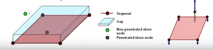
- So when slave node is approaching towards the master and when it is at the edge of the master imaginary gap the radioss will form a spring between the slave node and that particular surface or segment.
- Slave and Master :
- The coarser the mesh, stiffer the structure will be, provided the material and structural properties are same. Master is generally meshed coarser so that the slave dose not penetrate master that is why we choose less deformable or highly stiffer structure as master and less stiff as slave.
- Body under analysis is slave, When we want to study forces and stresses, we consider that body as slave For E.g, Consider Car hitting barrier in this case Barrier will act as master and car is slave as we need to analyse the deformation, forces and stresse on the car after hiting barrier.
- More the number of slave nodes, more is the calculations.
- Type 2 : tied node to surface
- Used in weld application ( Tie of surfaces )
- Type 7 : Nodes to surface contact
- Interface type 7 is a general purpose interface and can simulate all types of impact between a set of nodes and a master surface.
- interface type 7 is non-oriented and slave nodes can belong to the master surface. Therefore, this interface can simulate auto-impact, especially buckling during a high speed crash.
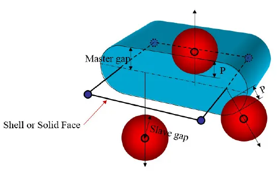
- The gap used in interface type 7 is rather different than those of the previous interfaces. The gap used is on both sides of the shell mid-surface, and a cylindrical gap is added around the edges.
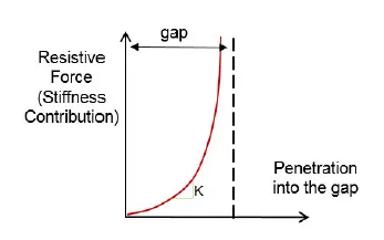
- interface type 7 is that the stiffness is not constant and increases with the penetration preventing the node from going through the shell mid-surface.
- Interface parameter :
- Igap : Determines how the size of the gap is calculated
- Gap min : Minimum gap for activation of interface.
- Inacti : Action to take if initial penetration exist.
- Istf : Affects how the stifness of the interface is calculated.
- Iform : Friction formulation
- Stmin : Minimum stifness to use in the interface.
- Idel : What to do with slave nodes and master segments if element fails (deleted) that they are attached to.
- gm : master element gap = t/2 ; t is thickness of master element for shell element.
- gs : Slave node gap = t/2 ; t is the largest thickness of shell elements connected to slave node.
- gs = √s/2 for truss or beam element with s being the cross section of the element.
- Type 11 : Edge to Edge Contact
- Type 11 interface can be added to capture the physics correctly when there is edge crossing another edge. Type 11 is defined by identifying master and slave lines (edges)
- Type 11 works similar to Type 7 in terms of: Penalty formulation, Gap definition, Search method.
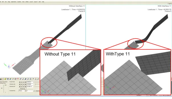
- As we can see in the above image that by using type 11 contact we can capture the scenario of edge crossing properly.
- Type 24 : General node or surface to surface Contact :
- Single surface, Surface to surface or nodes to surface contact interface using penelty method with constant stiffness.
- Simila to other types of contact gap is defined arount the master segment and slave nodes.
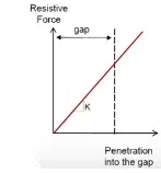
- Type 24 is recommended for all models where there is no physical gap (solids to solids).
- Type 24 is not recommended for airbag modeling when using FVM as some intersection may occur because of linear stiffness and may lead to negative volume for the polyhedron elements
Meshing of Bumper Assembly :
- First the giveen model is imported to Hypermesh and using automesh(F12) meshing is performed with required element size 6mm.
- Appropriate connectors are used for some places.
- All the mesh errors are removed.
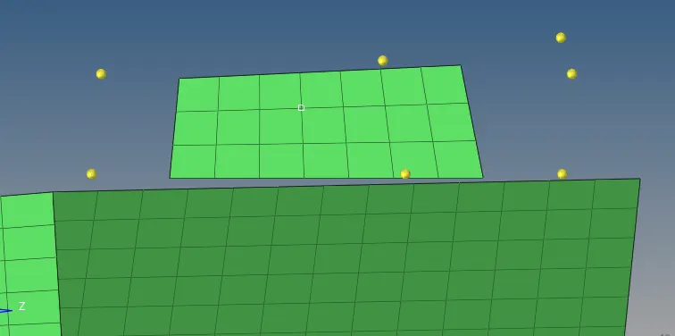
Final meshed model:
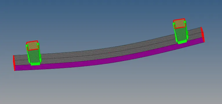
* Now for comparison andstudy of different typrs of Interfaces we are considering following six Cases:
- Run the crash tube model as it is.
- Change the Inacti=6 and run.
- Create the type 11 contact and run.
- Remove both notches and remove boundary condition on rigid body node then run.
- Create a new notch in the middle ,select the whole section and run.
- Create a new notch with nodes only from opposing 2 faces and run.
CASE 1) Run the crash tube model as it is.
- In this case first the files are directly imported to hypercrash and as we can see the interface card used in the model.
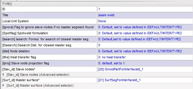
- Type 2 contact card is generally used for weld applications.
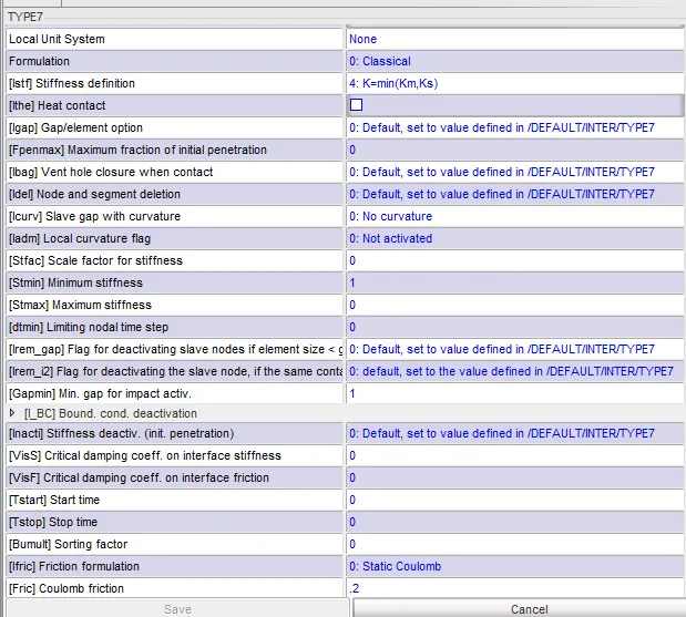
- Radioss simulation is peformed and the results are obtained.
- Energy Error :
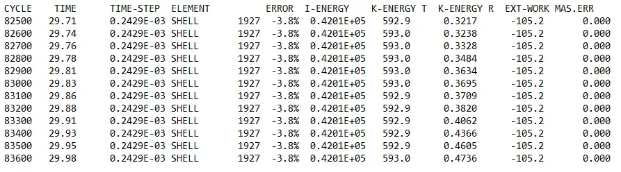
- Number of cycles at the end of the simulation is 83600 and the enrgy error is -3.8 %.
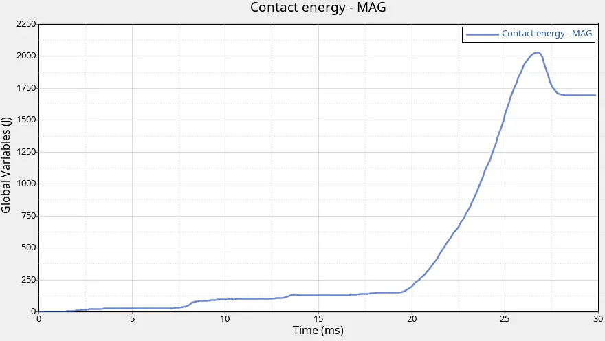
- Plot for energies :
Explanation:
- When friction is included in a contact definition, positive contact is to be expected. Friction shouldresult in positive contact energy. In the absence of friction, you would hope to see a small net contact energy (net = sum of slave side energy and master side energy).small net means 10% of peak internal energy might be considered acceptable for contact energy in the absence of contact friction.
- In this case maximum contact energy is greater than 2000J and it is at t= 26ms approx.
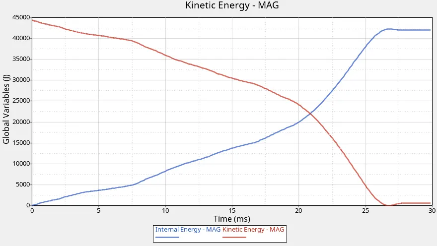
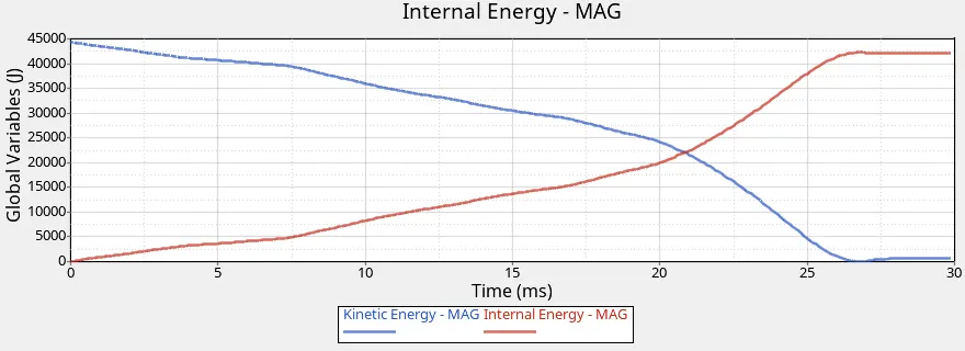
- We observe reverse characteristics for the curves of internal energy and kinetic enrygy. The curve for internal energy starts increasing its maximum value is greater than 40000J and Kinetic energy is decreasing rapidly as the deformation reaches to maximum value.
- Hourglass energy will be zero.
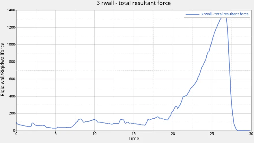
- The maximum rigid wall force after crush tube is impacted on rigid wall is approximately 1300 KN at t= 26ms.
- A rigid body is an idealization of a solid body in which deformation is neglected. In other words, the distance between any two given points of a rigid body remains constant in time regardless of the external forces exerted on it.
- A rigid wall is a nodal constraint applied to a set of slave nodes in order to avoid the node penetration to the wall. If contact is detected, then the slave node acceleration and velocity are modified. Mainly to constrain movement of a moving body after impact, We will be using a cylindrical wall.
- Displacement Contour:
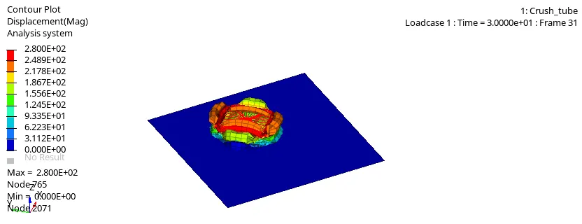
- Maximum displacement : 2.800E+02 at node 765.
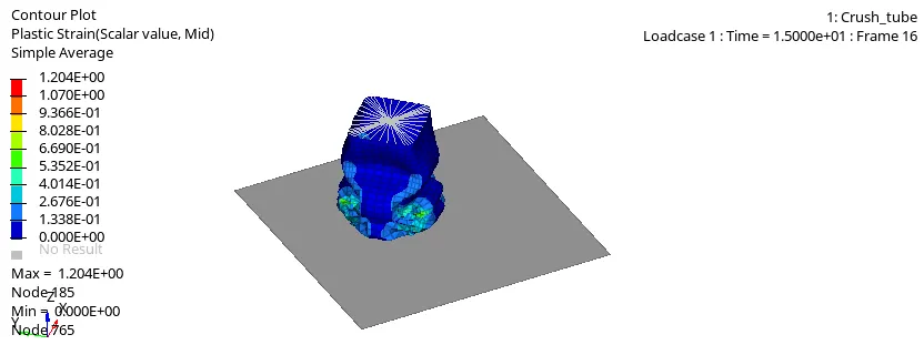
- Plastic Strain contour:
- Von mises contour plot:
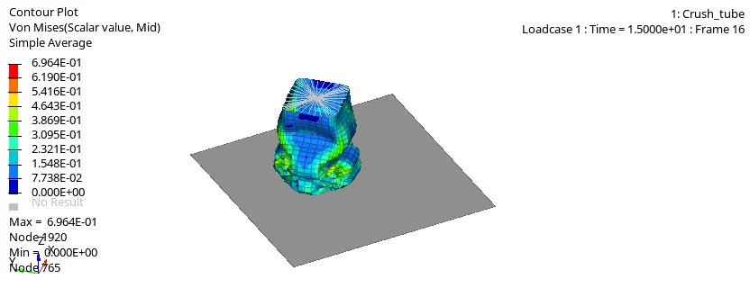
- Maximum value is 6.964E-01 at node 1920.
CASE 2) Change the Inacti to 6 and run
- In this case the value of the Inacti is chanaged to 6.
- Inacti is used for the actions to take if initial penetration exist.
What is Initial Penetration?
- Penetration is defined as the overlap of the material thickness of shell elements, while Intersection is defined as elements that actually pass completely through one another All models and especially impact models should be checked for penetrations and intersections and depenetrated to ensure the integrity of the model Penetrations adversely affects results and should be removed.
- Initial Penetration condition:
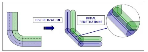
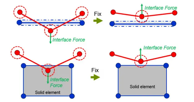
- Intersections result if slave nodes are past the master segment (shells or solids). This condition can cause locking situations leading to computation failure. If slave nodes lie on the master segment an ERROR will occur because of the Type 7 contact stiffness definition.
- There is fixing algorithm exist for different options we select for Inacti.
- Options for Inacti:
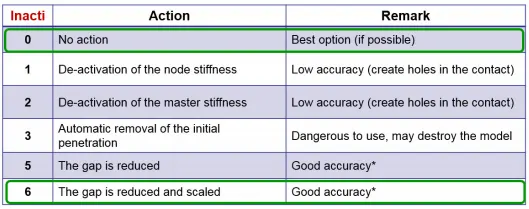
- For case 2 radioss simulation is performed after changing Inacti value to 6.
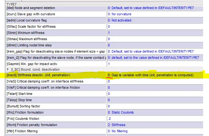
- Energy error:
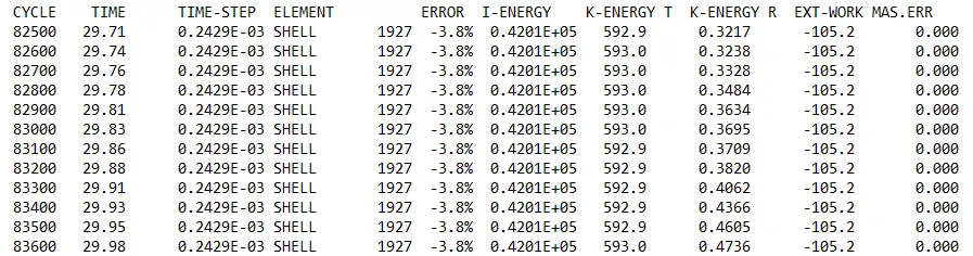
- The number of cycles at the end of the simulation are 83600 and the energy error is -3.8%.
- Contact Energy Plot:
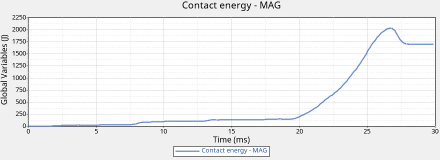
- Maximum contact energy is slightly greater than 2000J at t= 26ms.
- Internal and Kinetic Energy :
- Total Resultant Force:
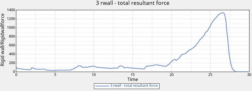
- As crus htube gets impacted on rigid wall the total resultant force gose on increasing and it reaches to maximum value greater than 1300KN at t=26ms.
- Displacement Contour Plot :
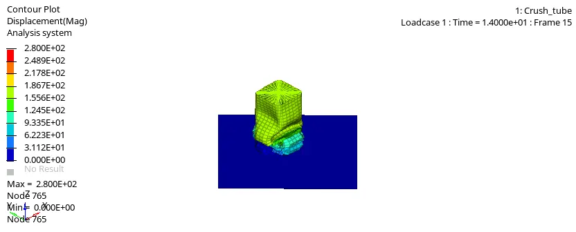
- Maximum Displacement is 2.800E+02 at node 765.
- Plastic Strain Contour Plot:
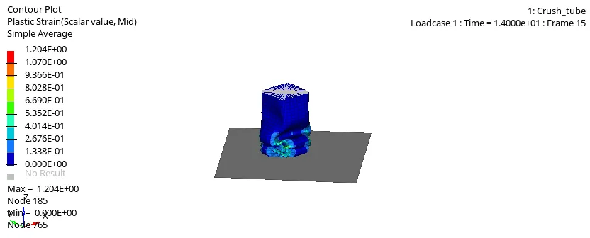
- The maximum plastic strain value is 1.204E+00 at node 185.
- Von Mises Contour Plot :
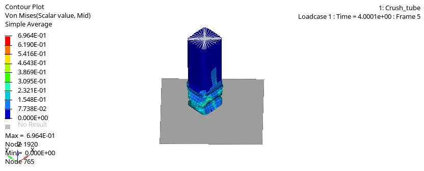
- The maximum value is 6.964E-01 at node 1920.
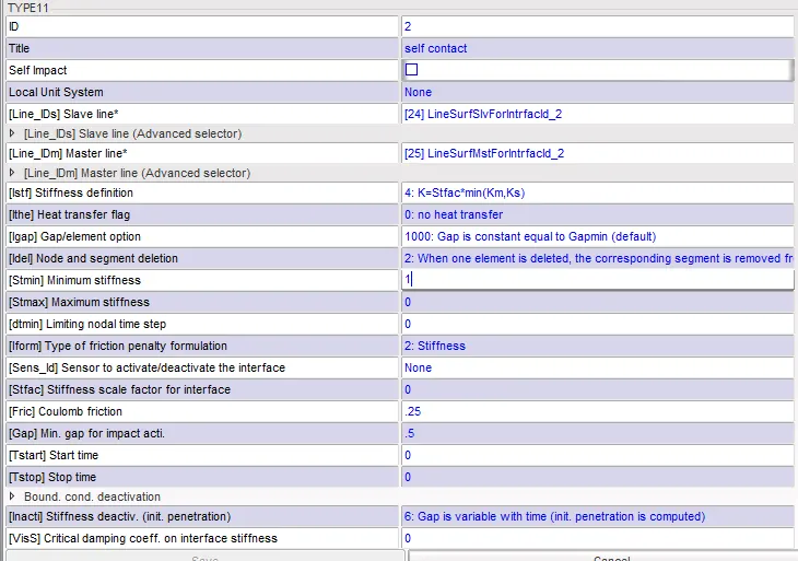
CASE 3) Create type 11 contact card and run the simulation:
- In this case type 11 card with recommended parameters is created and the radioss simulation is performed.
- Energy Error:
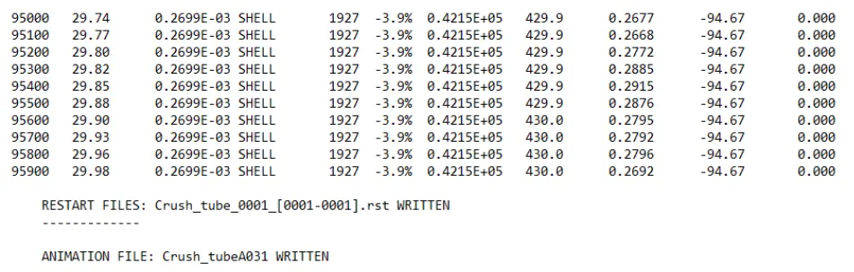
- Number of cycles are 95900 and the enrgy error is -3.9%.
- Contact Energy Plot:
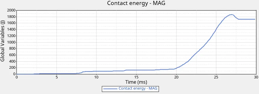
- Since we are using edge to edge contact it will capture when edge is crossing another edge.
- Maximum contact energy is slightly greater than 1800J at t= 26ms.
- Plot of Kinetic Energy and Internal Energy:
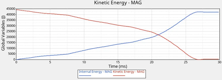
- Kinetic enrgy decrease rapidly from t=20ms and internal Energy is increasing and reaches maximum value greater than 41000J at t=26ms.
- Total Resultant Force:
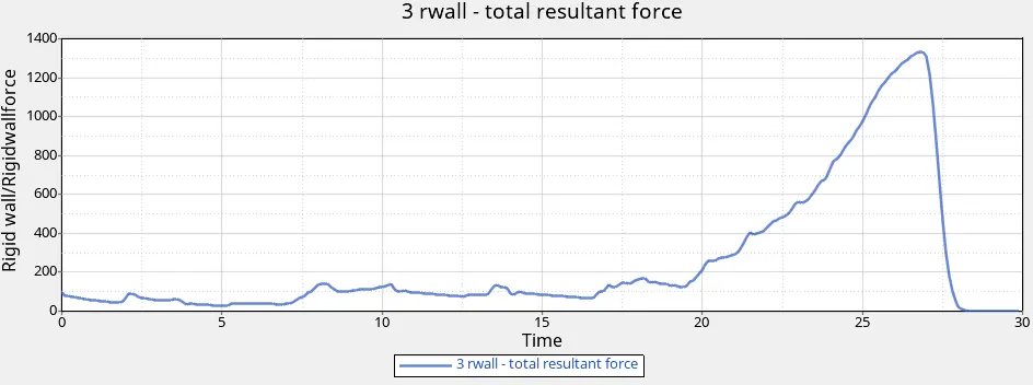
- The maximum total resultant force is approximately 1300KN at t=26ms.
- Displacement Contour Plot:
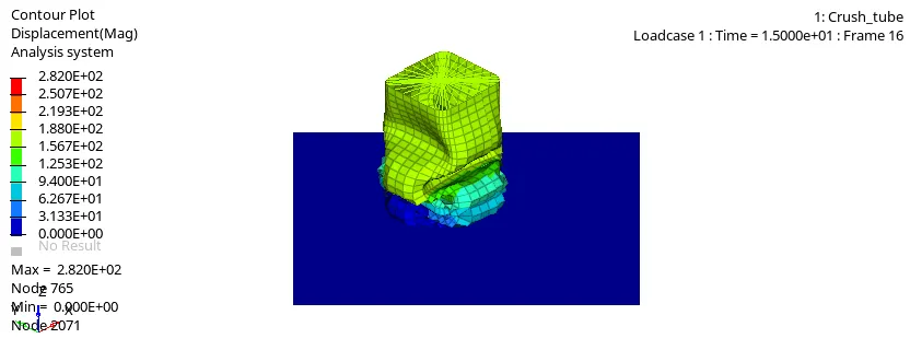
- The maximum displacement is 2.820E+02 at node 765.
- Plastic strain Contour Plot:
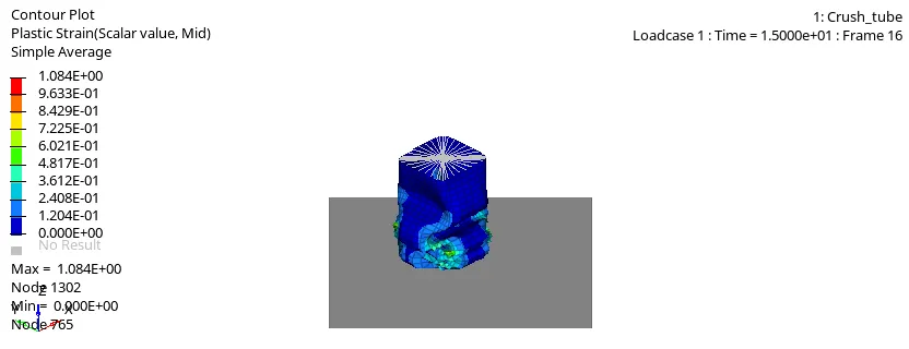
- Maximum Plastic Strain is 1.084E+00 at node 1302.
- Von mises Contour Plot :
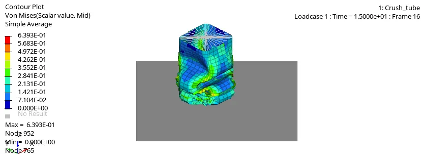
- Maximum Value is 6,393E-01 at node 952.
CASE 4) Remove both notches and remove boundary condition on rigid body node then run :
- In this case all the notches are removed using node edit- align node option and also boundry conditions on rigid body are removed.
- For this case the previous crush tube input file is imported and necessary modifications are done then Radioss simulation is performed.
- Energy Error:
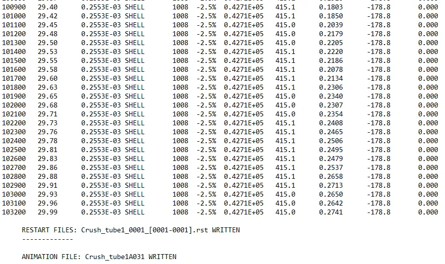
- Energy error at the end of the simulation is -2.5%.
- Plot of Contact Energy:
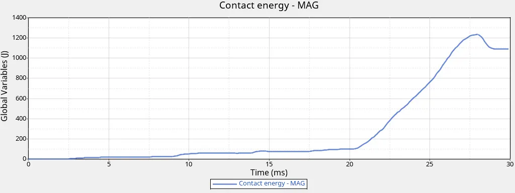
- We observed that contact energy increases rapidly after t=20ms and it reaches to maximum value slightly greater than 1200J at t=26ms approx.
- Contact energy starts to increase from t=20 ms and reaches to maximum value as at the end of simulation contact forces are increasing.
- Plot of Internal Energy and Kinetic Energy:
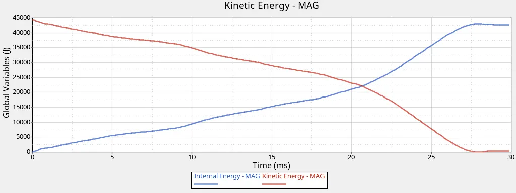
- Internal energy is increasing and Kinetic energy is decreasing and the nature of graph is similar to previous cases.
- Plot of Total Resultant Force:
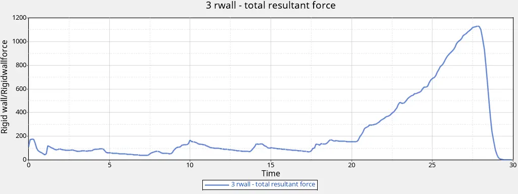
- Total resultant force increases rapidly from t=20ms and it reaches to maximum value greater than 1100KN.
- Displacement Contour Plot:
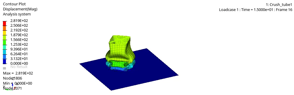
- Maximum displacement is 2.819E+02 at node 1806.
- Plastic Strain Contour Plot:
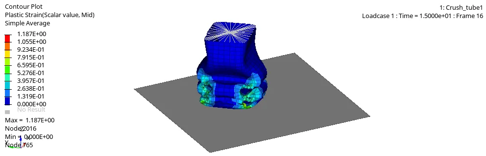
- Maximum Plastic strain is 1.187E+00 at node 2016.
- Von mises Contour Plot:
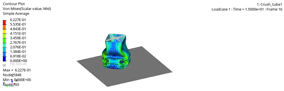
- Maximum value is 6.227E-01 at node 1848.
Explanation:
** Effect of analysis with Notch and without Notch:
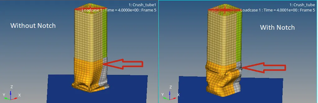
- As we can see that In case of analysis witout Notch the deformation started at the bottom but in case of analysis with notch the deformation or bending starts at the notch area.
- we also observed that at notch are the value of stress is higher.
- Due to no boundry conditions of rigid wall the ressultant wall forces are also less as compared to other cases.
CASE 5) Create a new notch in the middle ,select the whole section and run :
- In this case we have created new notch at middle part of crush tube and radioss simulation is performed.
- COntact card is similar to that of previous case.
- Energy Error:
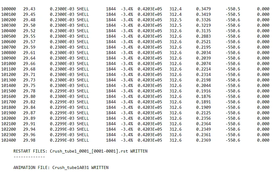
- Energy error at the end of the simulatiopn is -3.4%.
- Plot of Contact energy:
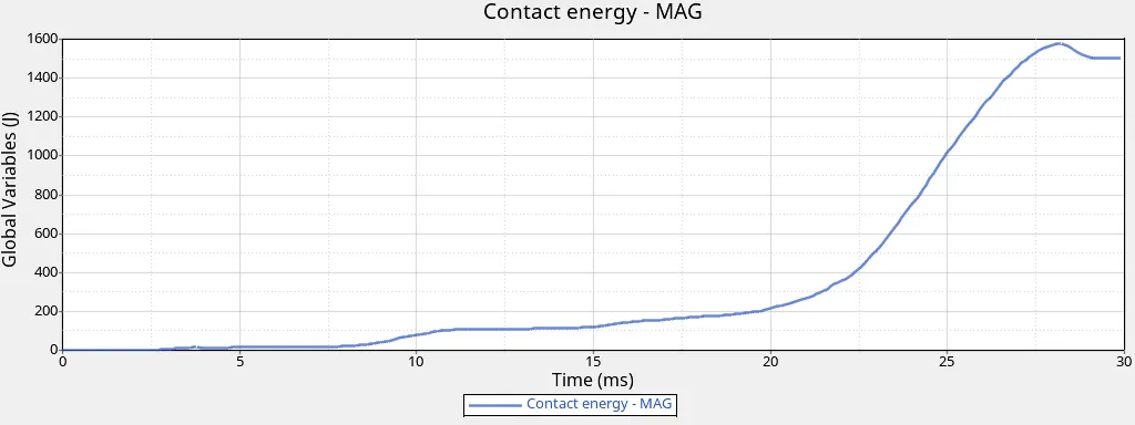
- Plot is similar to the case 3 but in this case there is only one notch are at tje middle so the contact energy is lesser as compared to case 3.
- Its maximum value is greater than 1500J at t=27ms.
- Plot of Kinetic Energy and Internal Energy:
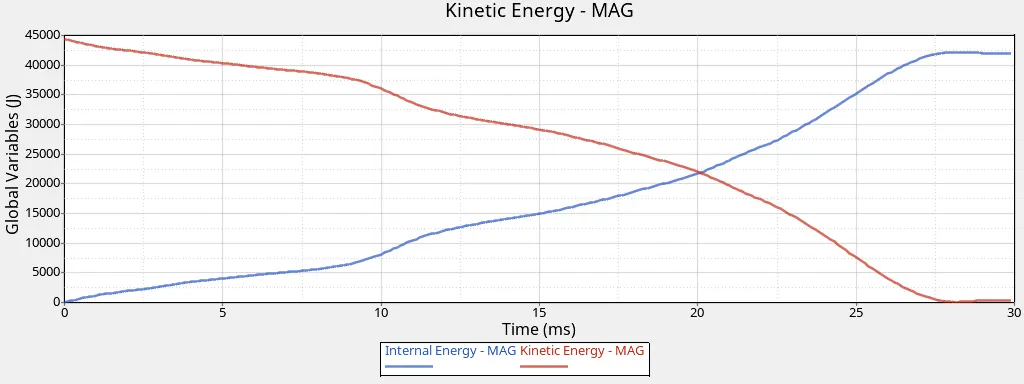
- Plot of total resultant force:
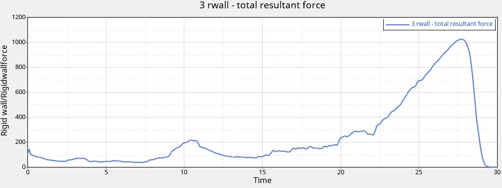
- maximum valu is approximately 1000KN at t=27ms.
- Displacement Contour Plot:
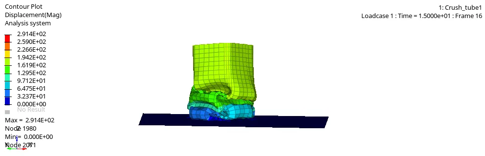
- Maximum value is 2.914E+02 at node 1980.
- Plastic Strain Contour Plot:
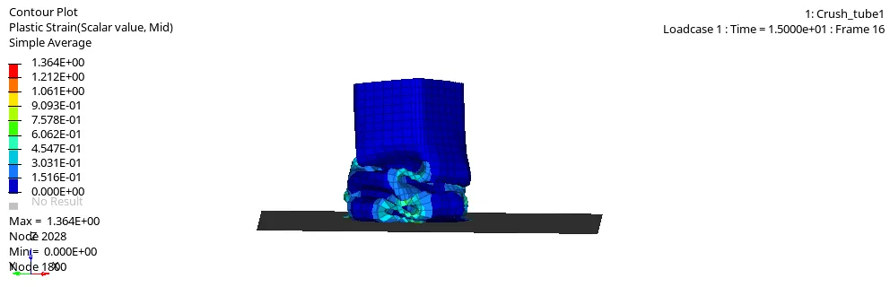
- maximum value is 1.364E+00 at node 2028.
- Von Mises Contour Plot:
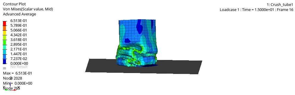
- Maximum valu is 6.513E-01 at node 2028.
Comparison:
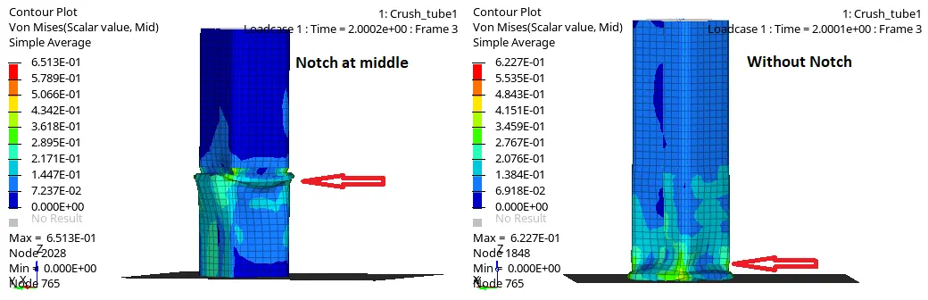
- Similar to case 4 the Deformation or buckling starts at Notch area. In this case Notch is created at middle so deformation starts from middle.
- we can clearly see the high stress concentration at the middle.
CASE 6) Create a new notch with nodes only from opposing 2 faces and run :
- In this case the new notches are created at two opposite faces. we can see the two notches in the figure below:
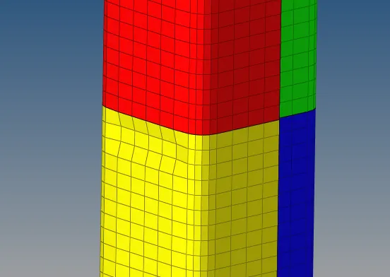
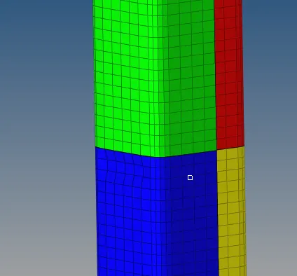
- All other parameters are same as case 5 and Radioss simulation is performed and results are obtained.
- Energy Error:
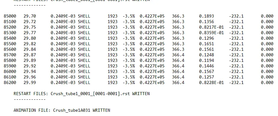
- Energy error at the end of simulation is -3.5%.
- Plot of Contact energy:
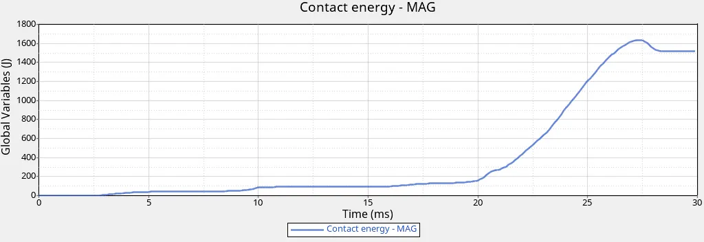
- The maximum contact energy is at t=26ms and it is approx. 1600J.
- Plot of Kinetic Energy and Internal Energy:
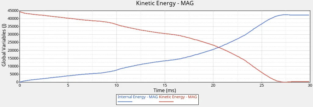
- Plot of total resultant force:
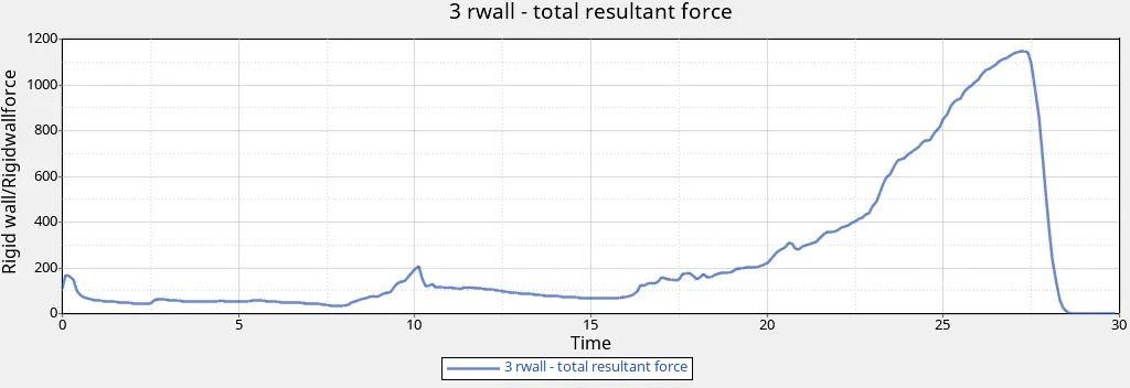
- Since the notch is present only on two opposite faces there is reduction in the total resultant force as comparted to case 5 where noptch is present on all four faces.
- Displacement Contour Plot:
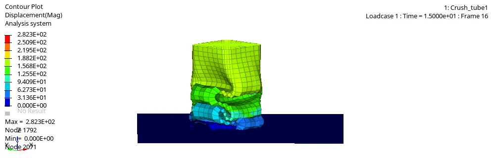
- The maximum value for displacement is 2.823E+02 at node 1792.
- Plastic Strain Contour Plot:
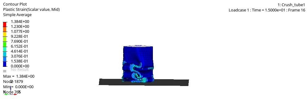
- The maximum value of plastic strain is 1.384E+00 at node 1879.
- Von Mises Contour Plot:
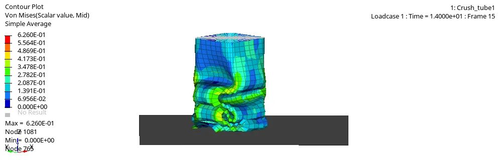
- The maximum value is 6.260E-01 at node 1081.
** Results and Conclusion:
- By changing the Interface parameters and creating new interface cardthe results of simulation are compared.
- There is some variation in energy error for each case. the energy error is less in simulation of crush tube withou notch. mass error is zero for all cases.
- if we compare the simulation with Notches and simulation without Notches the deformation or we can say buckling starts at the notch area and for without notch case the deformation or buckling starts at the bottom at point of contact of rigid wall and tube.
- Due to stress concentration the crush tube get easily deform at notch area.
- So we can say that Notch can be used to determine the nature of deformation in any crash analysis.
- Hourglass energy is zero in all cases.
- Contact Energy is higher for case 1 and case 2 where type 7 and type 11 interface types are used.